


I. Core Principle: How Does Compressed Air Convert to Mechanical Power?
As the core actuator in pneumatic systems, pneumatic air cylinders rely on a precise combination of fluid mechanics and mechanical structure to convert energy. A detailed analysis must cover three key aspects: air supply characteristics, structural details, and advantage principles.
From the perspective of air supply basics, industrial compressed air requires drying, filtration, and pressure stabilization treatments. Typically, the pressure dew point should be below -20°C, and the particle size of solid impurities should be less than 5μm to prevent damage to internal components of the cylinder. When the treated compressed air enters the cylinder chamber through a solenoid valve, it first passes through the air inlet hole on the end cap and then is evenly distributed to both sides of the piston via a buffer sleeve (equipped in some models) to ensure stable pressure acting on the piston end face.
Taking a double-acting cylinder with a single piston rod as an example, the inner wall of the cylinder barrel undergoes precision honing, achieving a surface roughness of Ra 0.2-0.4μm. It works with combined seals (usually polyurethane U-rings + guide rings) on the piston to achieve bidirectional sealing. The guide rings, mostly made of polytetrafluoroethylene (PTFE), not only reduce direct friction between the piston and the cylinder barrel but also ensure the piston's coaxiality, preventing deflection of the piston rod. When compressed air enters the rodless chamber, the gas pressure pushes the piston toward the rod chamber, while the gas in the rod chamber is discharged through the exhaust hole. During the exhaust process, some models use a muffler to reduce noise (typically lowering noise from 85dB to below 65dB). Conversely, when air enters the rod chamber, the piston moves in the opposite direction, completing a reciprocating cycle.
In terms of energy conversion efficiency, the mechanical efficiency of the cylinder is mainly affected by seal friction and gas compressibility. Under ideal conditions, the conversion efficiency from pressure energy to mechanical energy can reach 95%. However, in practical applications, due to seal friction losses (accounting for approximately 5%-10%) and gas leakage (accounting for approximately 2%-5%), the actual efficiency is usually maintained between 70%-90%. Nevertheless, compared with hydraulic systems, pneumatic cylinders do not require complex circuits such as oil tanks and pipelines, resulting in a shorter energy transmission path and faster response speed. The delay time from air supply to piston rod movement can be controlled within 0.02-0.05 seconds, making them particularly suitable for high-frequency operation scenarios (e.g., electronic component sorting, which can complete 30-50 cycles per minute).
Their environmental adaptability advantages also deserve emphasis: compressed air itself is non-toxic and odorless, and even if leakage occurs, it will not contaminate workpieces or the environment. Therefore, they are widely used in the food packaging industry (e.g., chocolate molding machines) and pharmaceutical preparation industry (e.g., vaccine filling equipment). Compared with electric actuators, pneumatic cylinders are more durable in humid environments (e.g., car wash equipment) and dusty environments (e.g., ore screening equipment), eliminating concerns about motor moisture damage or dust entering the windings causing malfunctions. Additionally, pneumatic cylinders have stronger overload resistance. When the load exceeds the rated value, the piston rod stops moving without burning out like a motor; normal operation can be restored simply by reducing the load, resulting in lower maintenance costs.
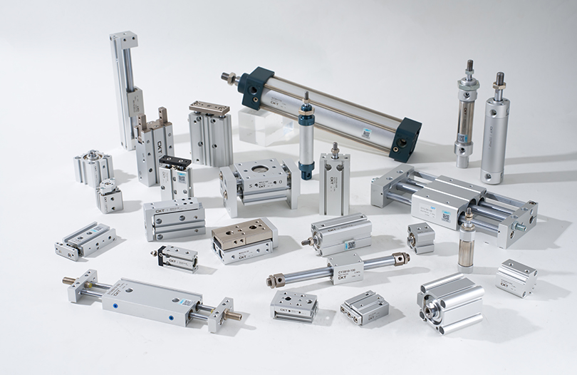
II. Type Analysis: Which Cylinder Type Suits Different Scenarios?
The classification of cylinder types is based on in-depth matching of structural design, performance parameters, and scenario requirements. Each type has its unique application logic and performance boundaries:
1. Linear Motion Type: Basic Choice for Conventional Scenarios
Single-Acting Cylinders: In addition to the common spring-return type, there are gravity-return types (suitable for vertically downward installation scenarios, such as silo gate opening) and air-pressure return types (achieving return through another low-pressure air circuit, suitable for narrow spaces where springs cannot be installed). Their structural feature is that only one air inlet is needed for control, saving the number of solenoid valves, and their cost is 15%-20% lower than that of double-acting cylinders. However, limited by the return method, their return force is usually less than the thrust force (the return force of spring-return types is approximately 30%-50% of the thrust force), and the stroke should not be too long (generally not exceeding 300mm, otherwise the spring is prone to fatigue failure). In practical applications, such as material positioning on assembly lines, the thrust of single-acting cylinders can be controlled by adjusting the air supply pressure (usually set to 0.3-0.5MPa) to avoid crushing workpieces, and magnetic switches can be used to accurately detect whether the piston is in place.
Double-Acting Cylinders: Based on installation methods, they can be divided into standard types (front flange, rear flange, foot mount, trunnion mount, etc.) and compact types (integrated cylinder barrel and end cap design, reducing length by 20%-30%). Both sides of the piston can withstand pressure, and the difference between thrust and pull force mainly stems from the cross-sectional area of the piston rod (the effective force-bearing area of the rod chamber is equal to the effective force-bearing area of the rodless chamber minus the cross-sectional area of the piston rod). Taking a cylinder with a bore diameter of 50mm and a piston rod diameter of 20mm as an example, the thrust of the rodless chamber is approximately 980N, and the pull force of the rod chamber is approximately 750N. Therefore, in vertical lifting scenarios with heavy loads, priority should be given to the force-bearing direction of the rodless chamber. In automated production lines, double-acting cylinders are often used in conjunction with guiding devices (e.g., linear guides) to improve motion accuracy. For example, in bolt tightening equipment on auto parts assembly lines, the cylinder drives the tightening shaft to move up and down, achieving a repeat positioning accuracy of ±0.1mm.
Miniature/Thin Cylinders: Miniature cylinders (with bore diameters such as 6mm, 8mm, 10mm) usually have cylinder barrels made of stainless steel, and piston rods undergo hard chrome plating (plating thickness 5-10μm) to withstand slight impacts. In the assembly of mobile phone camera modules, miniature cylinders need to push lens components for micron-level positioning, so high requirements are placed on the motion stability of the cylinder. They are usually equipped with throttle valves (e.g., needle valves) to control the speed within 50-100mm/s. Thin cylinders (with bore diameters 20mm-100mm) have end caps manufactured through stamping, reducing weight by 40% compared with standard types, making them suitable for installation in narrow spaces such as between printing machine rollers and under CNC machine tool turrets. Some thin cylinders also integrate magnetic switch mounting grooves, eliminating the need for additional brackets and saving installation time. They adopt a double-seal structure (primary seal + secondary seal), with a leakage rate controlled below 5mL/min (under standard conditions).
2. Rodless Cylinders: Space-Optimized Solution for Long-Stroke Scenarios
The core technology of mechanically coupled rodless cylinders lies in the sealing system. A double-layer sealing strip (inner polyurethane sealing strip and outer nitrile rubber dust-proof strip) is used at the slot on the cylinder barrel. The sealing strip is fixed by a sealing pressure block on the end cap to ensure no gas leakage. The connection between the slider and the piston is made of high-strength alloy material (e.g., 6061-T6 aluminum alloy) with anodization treatment (oxide film thickness 10-15μm), increasing wear resistance by more than 3 times. During operation, the slider must move in conjunction with a guide rail (e.g., built-in linear bearing) to avoid damage to the sealing strip caused by eccentric loads. The maximum allowable eccentric load is usually 10%-15% of the rated load. For example, in the chassis conveying link of an automobile assembly line, a mechanically coupled rodless cylinder needs to drive a chassis weighing 50kg to move with a stroke of up to 5m. In this case, a reinforced guide rail should be selected, and the speed should be controlled at 0.8-1.2m/s to avoid equipment vibration caused by excessive inertia.
The magnetic rings of magnetic rodless cylinders are made of neodymium-iron-boron high-strength magnetic material with a magnetic energy product of 35-40MGOe. Synchronous movement is achieved through the magnetic attraction between the inner magnetic ring on the piston and the outer magnetic ring on the external moving body. To ensure stable magnetic force, the gap between the inner and outer magnetic rings should be controlled at 0.5-1mm, and the cylinder barrel material must be non-magnetic (e.g., aluminum alloy, 304 stainless steel). Their advantage lies in the rodless structure, which provides better sealing performance with almost zero leakage, making them suitable for scenarios with high cleanliness requirements (e.g., semiconductor wafer conveying). However, their load capacity is limited by magnetic force, usually with a maximum load of no more than 30kg, and they are not suitable for high-frequency start-stop scenarios (otherwise, the magnetic ring is prone to demagnetization).
3. Rotary Cylinders: Specialized Actuators for Rotational Motion
Rack-and-Pinion Rotary Cylinders: The rack and piston are designed as an integrated unit, and the rack tooth profile is mostly involute (module 1-3). It works with high-precision gears (transmission accuracy up to grade 5) to ensure a rotation angle error of less than ±0.5°. Some models are equipped with angle adjustment screws, allowing fine adjustment of the rotation angle within ±5° to meet precise positioning requirements. In valve control scenarios (e.g., pipeline valves in water treatment plants), rack-and-pinion rotary cylinders can control the rotation speed by adjusting the air supply pressure (usually 0.4-0.6MPa) and achieve valve opening, closing, and intermediate position holding with the assistance of position sensors, with a service life of more than 1 million cycles.
Vane-Type Rotary Cylinders: The vane and rotor are connected by a key, and seals (usually nitrile rubber + PTFE combined seals) must be installed on both sides of the vane to prevent gas leakage from one side to the other. The inner wall of the stator requires precision machining to ensure a sealing gap of 0.02-0.05mm between the stator and the vane; otherwise, efficiency will decrease significantly. The rotation angle of vane-type rotary cylinders is usually fixed angles such as 90°, 180°, and 270°. For arbitrary angle control, an angle controller is required. Due to structural limitations, their output torque is small (e.g., a vane-type cylinder with a bore diameter of 40mm has a maximum torque of approximately 5N·m), so they are mostly used for light fixture rotation (e.g., clamping small workpieces). The seals need to be replaced regularly (usually every 3-6 months) to ensure sealing performance.
4. Specialized Types for Extreme Environments: Adaptive Design for Harsh Conditions
In high-temperature environments (e.g., steel billet handling equipment in the metallurgical industry, with an operating temperature of 200-300°C), cylinders must use high-temperature-resistant materials: the cylinder barrel is made of 316L stainless steel (which can withstand temperatures below 300°C), the seals are made of fluororubber (long-term operating temperature -20°C to 200°C, with short-term resistance up to 250°C), and the piston rod surface is coated with ceramic (hardness up to HV1000 or higher, increasing wear resistance by 5 times). Additionally, heat sinks need to be added at the end caps to prevent heat transfer to the seals causing aging.
In corrosive environments (e.g., marine engineering equipment in contact with seawater salt), cylinders require comprehensive anti-corrosion treatment: the cylinder barrel is made of 316L stainless steel with passivation treatment, the piston rod is made of 316L stainless steel or undergoes chrome plating (plating thickness 20-30μm) with sealing treatment, end caps, pistons, and other components are all made of stainless steel, and seals are made of fluororubber or perfluoroether rubber with strong corrosion resistance. Some models also install anti-corrosion filters at the air ports to further prevent corrosive gases from entering the cylinder interior.
In cleanroom environments (e.g., semiconductor chip manufacturing, requiring ISO Class 1 cleanliness), cylinders must meet low particle emission and low volatility requirements: the cylinder barrel and piston rod are made of 316L stainless steel with precision polishing (surface roughness Ra 0.1-0.2μm) to prevent dust adhesion; non-metallic components such as seals and guide rings are made of low-particle-emission materials such as PTFE or modified polyethylene, and undergo high-temperature cleaning to remove volatile substances; the cylinder surface undergoes anti-static treatment to prevent static adsorption of dust. Furthermore, the exhaust of cleanroom-specific cylinders must be treated with a high-efficiency particulate air (HEPA) filter to avoid polluting the cleanroom environment with exhausted gas.|
III. Selection Guide: Accurate Matching of Requirements Through Five-Dimensional Parameters
Cylinder selection directly determines equipment stability and efficiency. It is necessary to systematically consider core dimensions such as load, pressure, and stroke, combined with practical operation steps:
1. Load Calculation: Clarify Required Thrust/Pull Force
First, analyze the load type (horizontal motion, vertical lifting, etc.). For horizontal loads, the friction coefficient (usually 0.1-0.3) must be considered, and for vertical loads, gravitational acceleration must be taken into account. The calculation logic for actual thrust is: actual thrust = actual working pressure × effective piston area × efficiency coefficient.
Among them, the actual working pressure needs to consider air supply pressure loss (e.g., for a pipeline length of 10m and a diameter of 8mm, the pressure loss is approximately 0.02-0.05MPa), so the actual working pressure is usually 5%-10% lower than the air supply pressure. For the effective piston area, in the case of a single-piston-rod cylinder, the effective area of the rodless chamber is the cross-sectional area of the cylinder barrel interior, and the effective area of the rod chamber is the cross-sectional area of the cylinder barrel minus the cross-sectional area of the piston rod. The efficiency coefficient depends on the cylinder precision: 0.7-0.8 for ordinary cylinders and 0.8-0.9 for high-precision cylinders (e.g., guided cylinders).
Taking an inclined pushing scenario at 30° as an example: the workpiece weight is 50kg, sliding on a guide rail (friction coefficient 0.15), with an acceleration of 0.8m/s² during the acceleration phase, and an air supply pressure of 0.6MPa (actual working pressure 0.55MPa). First, calculate the total load force: the component of gravity in the inclined direction = 50kg × 9.8m/s² × sin30° ≈ 245N; friction force = 50kg × 9.8m/s² × cos30° × 0.15 ≈ 63.6N; inertial force = 50kg × 0.8m/s² = 40N; total load force = sum of these three parts, approximately 348.6N. If the rodless chamber is used for force bearing and the efficiency coefficient is 0.8, the required effective piston area = total load force / (actual working pressure × efficiency coefficient), calculated to be approximately 7.97×10^-4 m². The bore diameter can be derived from the effective area, calculated to be approximately 31.6mm. In practice, a standard bore diameter of 40mm should be selected (standard bore diameter series: 12, 16, 20, 25, 32, 40, 50, 63, 80, 100mm, etc.). At this time, the actual thrust = 0.55MPa × effective area of the rodless chamber for a 40mm bore diameter × 0.8 efficiency coefficient, approximately 552N. The safety factor (ratio of actual thrust to total load force) is approximately 1.58, meeting the 1.5-2 safety factor requirement.
2. Stroke and Buffering: Avoid Motion Impact
Stroke selection must consider the actual motion distance of the equipment and a safety margin. In addition to the conventional 5%-10% margin, the following factors should also be considered: if the cylinder is used to push workpieces to a specified position, an adjustment space for workpiece positioning errors (usually 5-10mm) must be reserved; if used for clamping workpieces, a compensation space for workpiece size deviations (usually 3-5mm) must be reserved. For long-stroke cylinders (>300mm), special attention must be paid to the rigidity of the piston rod to prevent bending under load. Generally, the ratio of bore diameter to stroke should be controlled within 1:10 (e.g., a bore diameter of 40mm with a maximum stroke of 400mm). If this ratio is exceeded, a thickened piston rod (e.g., increasing the piston rod diameter from 16mm to 20mm) or a guiding device (e.g., double-shaft cylinder, guided cylinder) should be selected.
The selection of the buffering system depends on the motion speed, load weight, and equipment precision requirements: when the speed is ≤0.3m/s and the load is ≤50kg, rubber buffering can be used (simple structure, low cost), but the buffering effect is limited, making it suitable for scenarios insensitive to impact (e.g., material pushing); when the speed is 0.3-0.8m/s and the load is 50-200kg, adjustable buffering is required(adjustable buffering is required) – achieved by installing a throttle valve on the buffer chamber to adjust the exhaust speed. This allows for flexible adjustment of the buffering force based on actual working conditions, making it suitable for most industrial scenarios (e.g., workpiece positioning on assembly lines). When the speed exceeds 0.8m/s and the load exceeds 200kg, a hydraulic shock absorber (installed independently at the end of the cylinder stroke) is necessary. It has a large buffering capacity and can reduce the impact acceleration from 10m/s² to below 2m/s², making it ideal for high-speed, heavy-load scenarios (e.g., large workpiece handling).
In addition, maintenance of the buffering system requires attention: the buffer chamber of adjustable buffering should be cleaned regularly (every 3-6 months) to prevent blockage of the exhaust hole by impurities, which would cause buffering failure. Rubber buffer pads should be inspected periodically (every 1-2 months); if aging or deformation is found, they must be replaced promptly to avoid increased impact noise and risk of equipment damage.
3. Installation and Detection: Adapting to Equipment Structure
The choice of installation method must comprehensively consider the equipment's spatial layout, force direction, and motion accuracy requirements:
Flange Mounting: Divided into front flange (mounted at the front end of the cylinder) and rear flange (mounted at the rear end of the cylinder). High-strength bolts (e.g., grade 8.8 or higher) should be used to connect the flange to the equipment, and the perpendicularity between the flange face and the cylinder axis must be ensured (perpendicularity error ≤0.1mm/m). This method is suitable for scenarios with fixed loads and high motion accuracy requirements (e.g., clamping by machine tool fixtures).
Trunnion Mounting: Includes fish-eye trunnions (allowing a certain angle of swing, usually ±5°) and trunnions with spherical bearings (swing angle up to ±10°). During installation, the fit clearance between the trunnion hole and the equipment connecting shaft must be ensured (usually 0.05-0.1mm) to avoid unstable motion caused by excessive clearance. It is suitable for scenarios where the load has slight swing (e.g., pushing devices on inclined conveyors).
Foot Mounting: Includes front foot mounts, rear foot mounts, and double-lug foot mounts. The connection between the foot mount and the equipment must be secure to prevent loosening under load. Due to the fact that the support points of the foot mount are far from the cylinder axis, its lateral force resistance is weak (lateral load usually does not exceed 10% of the rated load). It is suitable for light-load scenarios with fixed motion directions (e.g., pushing small workpieces).
Pivot Mounting: The cylinder is fixed to the equipment bracket via a pivot pin, allowing the cylinder to swing around the pivot pin (swing angle usually ±15°). The fit between the pivot pin and the cylinder trunnion hole should use a transition fit (e.g., H7/g6), making it suitable for scenarios where the load has a large swing angle (e.g., material flipping mechanisms).
For position detection, in addition to common magnetic switches, there are also limit switches and photoelectric sensors: Magnetic switches detect the piston position by sensing the magnetic ring on the piston, with a fast response speed (≤1ms). During installation, attention must be paid to the alignment accuracy with the magnetic ring (deviation ≤1mm); otherwise, detection failure may occur. Limit switches are triggered by mechanical contact, offering high reliability but slow response speed (≥10ms), making them suitable for scenarios with low response speed requirements (e.g., equipment limit position protection). Photoelectric sensors achieve positioning by detecting the blocking signal of the piston or slider, requiring no contact with the cylinder body, making them suitable for corrosive or high-temperature environments. However, it is necessary to ensure that there is no strong light interference in the detection area.
4. Speed Control: Matching Working Condition Requirements
Cylinder speed is mainly controlled by air intake throttling or exhaust throttling, and the application scenarios and adjustment logic of these two methods differ significantly:
Air intake throttling involves installing a throttle valve at the cylinder's air inlet to control the extension or retraction speed of the piston rod by restricting the intake flow. This method has the advantage of simple adjustment and is suitable for scenarios with low requirements for speed stability (e.g., ordinary material pushing). However, when the load changes, the speed fluctuates significantly (fluctuation range up to ±20%). For example, when the weight of the pushed workpiece increases from 10kg to 20kg, the speed may decrease from 150mm/s to below 100mm/s if air intake throttling is used, affecting the production cycle.
Exhaust throttling involves installing a throttle valve at the cylinder's exhaust port to indirectly adjust the motion speed by controlling the exhaust speed. Since exhaust throttling maintains a certain back pressure inside the cylinder, it effectively suppresses speed fluctuations caused by load changes (fluctuation range can be controlled within ±5%), making it more suitable for scenarios with high requirements for speed stability (e.g., part alignment in precision assembly). During actual adjustment, attention must be paid to the installation position of the exhaust throttle valve: for double-acting cylinders, throttle valves should be installed at the exhaust ports of both the rodless chamber and the rod chamber to independently adjust the extension and retraction speeds.
In addition, cylinder speed is also affected by the air supply flow rate and pipeline diameter. When the pipeline length exceeds 10m, the pipeline diameter should be appropriately increased (e.g., from 8mm to 10mm) to avoid speed reduction due to insufficient flow rate. If ultra-high-speed motion (>1m/s) is required, a large-flow solenoid valve (bore diameter ≥15mm) should be selected, combined with a short pipeline (≤5m) to reduce gas flow resistance.
5. Accessory Matching: Ensuring Smooth System Operation
The rational selection of accessories directly affects the operational stability and service life of the cylinder, and key accessories such as pipelines, solenoid valves, and connectors must be considered one by one:
For pipelines, the material should be selected based on the working pressure and ambient temperature: Polyurethane pipelines can be used for normal-temperature, low-pressure scenarios (pressure ≤1MPa, temperature -5℃ to 60℃) due to their good flexibility and light weight, making them suitable for motion scenarios with frequent bending (e.g., cylinders at the end of robotic arms). Nylon pipelines should be used for medium-temperature scenarios (temperature -20℃ to 120℃) due to their better aging resistance. Polytetrafluoroethylene pipelines are suitable for corrosive environments as they can withstand strong acids and alkalis. The pipeline diameter must match the cylinder interface; common cylinder interface specifications include G1/8, G1/4, and G3/8, corresponding to pipeline diameters of 6mm, 8mm, and 10mm respectively. Using an undersized pipeline diameter will result in insufficient flow rate and reduced cylinder speed.
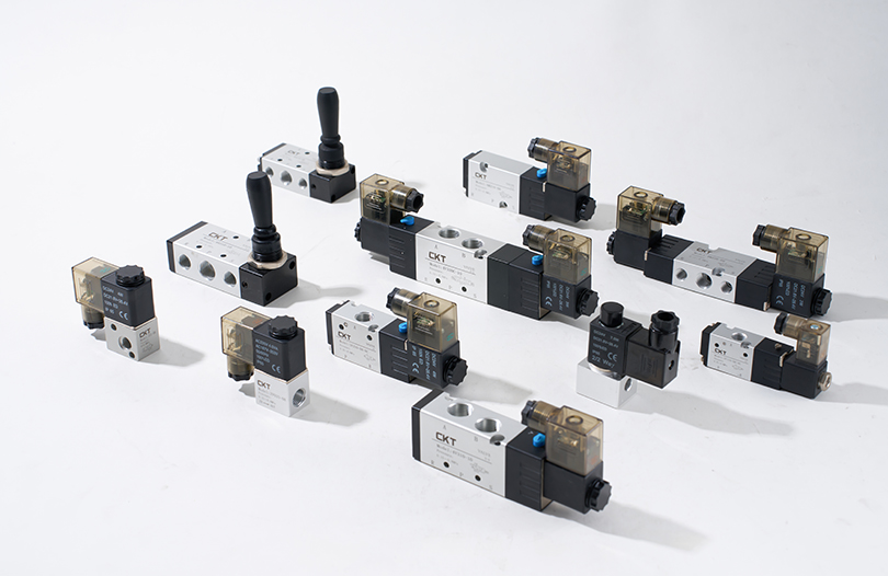
Solenoid valves are core components for controlling cylinder movement and should be selected based on the cylinder type and motion requirements: Single-acting cylinders require 2/3-way solenoid valves (controlling air intake and exhaust), while double-acting cylinders require 5/2-way solenoid valves (controlling air intake and exhaust for both the rodless and rod chambers). The voltage specification of the solenoid valve must match the equipment power supply (common specifications include DC24V and AC220V), and the response time should be ≤10ms to meet high-frequency motion requirements. Additionally, in dusty or humid environments, solenoid valves with a protection level of IP65 or higher should be selected to prevent damage to internal components.
Connectors are used to connect pipelines to cylinders and solenoid valves, and models matching the pipeline diameter and interface specifications should be selected: Quick-connect fittings allow for easy installation and are suitable for scenarios requiring frequent disassembly (e.g., equipment commissioning phases). Compression fittings offer better sealing performance and are suitable for scenarios requiring long-term stable operation (e.g., production line equipment). In environments with large vibrations (e.g., machine tools), connectors with locking nuts should be used to prevent loosening and leakage.
IV. Maintenance Tips: How to Extend the Service Life of Pneumatic Cylinders?
Scientific maintenance can significantly improve cylinder reliability and reduce the incidence of failures. The core lies in four key aspects: air supply purification, seal protection, regular inspection, and fault diagnosis. Below are detailed practical methods:
1. Air Supply Purification: Reducing Internal Wear
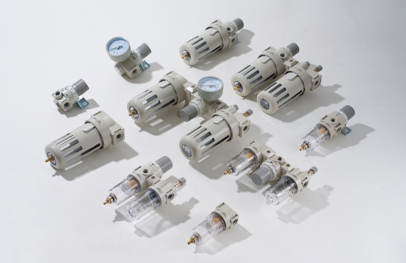
Moisture, oil, and impurities in compressed air are the main causes of internal wear of cylinders and aging of seals. A three-stage purification system is required to achieve efficient filtration:
Primary filtration (pre-filtration): A main line filter is installed at the outlet of the air compressor with a filtration precision of 5-10μm, mainly used to remove large particulate impurities (e.g., rust, dust) from the air and separate part of the liquid water and oil. The drain valve should be opened regularly (every 1-2 weeks) to drain water. In environments with high humidity (e.g., rainy seasons in southern regions), the frequency of draining should be increased (1-2 times per day) to prevent water accumulation inside the filter.
Secondary filtration (precision filtration): A precision filter is installed in the cylinder air supply circuit with a filtration precision of 1-5μm to further remove fine impurities and oil mist. The filter element of the precision filter should be replaced regularly (every 3-6 months). In dusty environments (e.g., ore processing workshops), the replacement cycle should be shortened (every 1-2 months). When replacing, the air supply should be turned off first, and the pressure inside the filter should be relieved to prevent impurities from entering the downstream circuit.
Tertiary filtration (oil mist treatment): For oil-free lubrication cylinders (used in some food and pharmaceutical industry equipment), an oil mist separator should be installed after the precision filter with a filtration precision of 0.01μm to remove trace oil mist from the air, ensuring that the oil content of the air entering the cylinder is ≤0.01mg/m³. The filter element of the oil mist separator should be replaced every 6-12 months, and a differential pressure gauge should be used to monitor the clogging status of the filter element. If the differential pressure exceeds 0.1MPa, the filter element must be replaced immediately.
In addition, the pressure of the pressure reducing valve should be stably adjusted within the rated working pressure range of the cylinder (usually 0.4-0.6MPa) to avoid damage to the seals caused by overpressure operation. If the equipment is idle for a long time (more than 1 month), the air supply should be turned off, and the compressed air inside the cylinder should be relieved to prevent internal corrosion.
2. Seal Protection: Blocking External Hazards
Seals are key components for preventing gas leakage and ensuring the normal operation of the cylinder. Targeted protection measures should be taken based on the application scenario:
Daily inspection: The surface of the cylinder piston rod should be inspected weekly for scratches or corrosion. If rust spots or scratches are found on the piston rod surface, they should be gently polished with fine sandpaper (800-1000 grit) immediately, and then special grease (e.g., lithium-based grease) should be applied to prevent damage to the seals. At the same time, check whether there is leakage at the connection between the cylinder end cap and the cylinder barrel. If leakage is found, tighten the connecting bolts (the torque must comply with the cylinder manual requirements to avoid cylinder barrel deformation caused by over-tightening). If leakage still occurs after tightening, replace the end cap gasket.
Seal replacement: When the cylinder has increased leakage (exceeding 10mL/min), significantly reduced motion speed, or jamming of the piston rod, the seals should be replaced promptly. Before replacement, the cylinder should be disassembled, and components such as the cylinder barrel and piston should be cleaned (cleaned with anhydrous ethanol or kerosene; corrosive solvents should be avoided). When replacing, seals consistent with the original model should be selected (attention should be paid to material matching, e.g., fluororubber seals for high-temperature scenarios), and a small amount of grease should be applied to the seal surface during installation to reduce installation resistance and avoid seal damage.
Dust protection: In dusty environments (e.g., woodworking workshops, cement processing plants), a dust cover (e.g., telescopic dust cover, foldable dust cover) should be installed at the extending end of the cylinder piston rod to prevent dust from entering the cylinder interior. The dust cover should be inspected regularly (every 2-4 weeks); if damage is found, it should be replaced immediately to prevent dust from entering the cylinder barrel through the piston rod and exacerbating internal wear.
3. Regular Inspection: Timely Troubleshooting
Regular inspection is an important means of preventing cylinder failures. Monthly, quarterly, and annual inspection systems should be established, with clear inspection items and standards:
Monthly inspection: Focus on checking the operating status of the cylinder, including whether the motion is smooth, whether there is abnormal noise (e.g., "hissing" leakage sound, "clacking" mechanical collision sound), and whether the piston rod moves smoothly (no jamming or deflection). At the same time, check the detection accuracy of the magnetic switch by manually pushing the piston and observing whether the magnetic switch can accurately detect the piston position. If detection failure occurs, adjust the installation position of the magnetic switch or replace the switch.
Quarterly inspection: Disassemble and inspect key components of the cylinder, including the piston, piston rod, and guide ring. Check whether there is wear on the piston surface (the piston should be replaced if the wear amount exceeds 0.1mm), the straightness error of the piston rod (the piston rod should be calibrated or replaced if the error exceeds 0.1mm/m), and the wear of the guide ring (the guide ring should be replaced if the clearance exceeds 0.2mm). In addition, check the surface roughness of the inner wall of the cylinder barrel; if obvious scratches or rust are found, the cylinder barrel should be repaired with honing tools or replaced.
Annual inspection: Test the overall performance of the cylinder, including thrust/pull force testing (measure the actual output force with a dynamometer; if the deviation from the rated value exceeds 10%, investigate the cause, such as seal wear or insufficient air supply pressure), leakage testing (measure the cylinder leakage at rated pressure; replace the seals if the leakage exceeds the standard value), and service life testing (simulate actual working conditions and operate continuously for more than 100,000 cycles to observe whether the cylinder has failures). At the same time, fully tighten the connecting bolts and connectors of the cylinder to prevent loosening caused by long-term vibration.
4. Fault Diagnosis: Quick Location and Resolution
When a cylinder fails, troubleshooting should follow the principle of "external first, internal second; simple first, complex second". Below are common faults and their solutions:
Fault 1: Cylinder moves slowly or not at all
Possible causes: ① Insufficient air supply pressure (improper pressure reducing valve adjustment or air compressor failure); ② Blocked or undersized pipeline (pipeline blocked by impurities or pipeline diameter not meeting requirements); ③ Solenoid valve failure (coil burnout or valve core jamming); ④ Aging seals (leakage caused by worn piston seals).
Solutions: ① Check the air supply pressure, adjust the pressure reducing valve to the rated pressure, and repair or replace the air compressor if it fails; ② Disassemble the pipeline and blow out the blocked part with compressed air; replace the pipeline with a larger diameter if the pipeline diameter is insufficient; ③ Check the solenoid valve coil voltage, replace the coil if it is burned out, and disassemble and clean the valve core if it is jammed; ④ Disassemble the cylinder and replace the aging seals.
Fault 2: Severe cylinder leakage
Possible causes: ① Damaged end cap gasket (loose bolts or aging gasket); ② Worn piston rod seals (scratched piston rod surface or aging seals); ③ Damaged cylinder barrel and piston seals (worn piston or aging seals); ④ Loose connectors (loosened connections caused by vibration).
Solutions: ① Tighten the end cap bolts and replace the gasket if it is aging; ② Repair the scratched piston rod surface and replace the piston rod seals; ③ Replace the piston and piston seals; ④ Tighten the connectors and replace them if they are damaged.
Fault 3: Abnormal noise during cylinder operation
Possible causes: ① Piston rod deflection (improper installation or worn guide ring); ② Failed buffering system (improper adjustment of buffer screws or worn buffer seals); ③ Impurities inside the cylinder barrel (impurities entering the cylinder barrel due to inadequate air supply purification); ④ Solenoid valve commutation impact (fast solenoid valve response speed or no buffering device).
Solutions: ① Correct the cylinder installation position and replace the worn guide ring; ② Readjust the buffer screws and replace the buffer seals if they are worn; ③ Clean the cylinder barrel and enhance air supply purification; ④ Install a throttle valve at the solenoid valve outlet to reduce gas flow rate, or select a solenoid valve with a buffering function.
Fault 4: Magnetic switch detection failure
Possible causes: ① Improper magnetic switch installation position (not aligned with the magnetic ring on the piston); ② Magnetic ring demagnetization (magnetic ring magnetic strength reduced due to high-frequency start-stop or high-temperature environment); ③ Magnetic switch failure (coil burnout or detection component damage); ④ Interference factors (strong magnetic field or high-frequency equipment interference nearby).
Solutions: ① Adjust the installation position of the magnetic switch to ensure alignment with the magnetic ring; ② Replace the demagnetized magnetic ring; ③ Replace the magnetic switch; ④ Keep away from strong magnetic fields or high-frequency equipment, or select an anti-interference magnetic switch.
V. In-Depth Analysis of Common Application Scenarios: Practical Solutions Based on Working Conditions
The application of pneumatic cylinders in various industries requires optimized design based on specific working conditions. The selection, installation, commissioning, and parameter settings of cylinders vary significantly across scenarios. Below is a summary table of core application parameters for four typical industries, followed by detailed practical solutions:
| Industry Field | Core Requirement | Recommended Cylinder Type | Key Parameter Requirements | Installation & Maintenance |
| Electronic Manufacturing | High Precision + Low Vibration | Miniature Guided, Cleanroom Cylinders | Bore 12-25mm, Repeat Accuracy ±0.02mm, Cleanliness ISO Class 5 | Install: Laser parallelism calibration (≤0.01mm/m), PTFE piping Maintain: Monthly surface cleaning, Quarterly seal check |
| Automotive Manufacturing | High Load + Long Service Life | Heavy-Duty, Rack-and-Pinion Rotary | Bore 80-125mm, Torque ≥50N·m, Strength ≥800MPa | Install: Dowel pin connection (clearance ≤0.03mm), Reinforced guides Maintain: Per-shift rod lubrication, Weekly buffer cleaning |
| Food Packaging | Pollution-Free + Easy Cleaning | Stainless Steel, Anti-Stick Coated | Body SUS316L, Ra ≤0.8μm, FDA Seals | Install: Away from product path, Food-grade tubing (Quarterly replacement) Maintain: Monthly microbial test, Semi-annual compliance check |
| Logistics & Warehousing | High Speed + High Reliability | High-Speed, Thin Cylinders | Bore diameter 32-63mm, speed 30-50 cycles/min, fatigue resistance ≥1 million cycles | Install: Floating joints (±3°), Quick exhaust valves Maintain: Monthly line wear check, Quarterly timing optimization |
1. Electronic Manufacturing Industry: Precise Control for Precision Assembly Scenarios
In precision scenarios such as mobile phone motherboard welding and chip packaging, cylinders need to achieve micron-level positioning and stable motion, with the core requirements of "high precision + low vibration":
Selection Adaptation: Prioritize miniature guided cylinders (e.g., bore diameter 12mm-25mm) with a dual-guide shaft structure, achieving a repeat positioning accuracy of ±0.02mm to avoid positioning deviations caused by eccentric loads in single-shaft cylinders. For chip handling, cleanroom-specific cylinders (ISO Class 5 or higher) with low-particle-emission coatings should be selected to prevent dust contamination of chip pins.
Installation & Commissioning: During installation, use a laser alignment tool to calibrate the parallelism between the cylinder axis and the workbench (error ≤0.01mm/m) to avoid lateral forces damaging precision components. PTFE pipelines (inner diameter 4mm-6mm) should be used to reduce the impact of airflow pulsation on motion stability; meanwhile, a precision pressure regulator (accuracy ±0.005MPa) should be installed at the cylinder air inlet to stabilize the working pressure at 0.3-0.4MPa, preventing welding deviations caused by pressure fluctuations.
Parameter Optimization: Use exhaust throttling for speed control, adjusting the speed to 30-50mm/s via a micro throttle valve, and matching with flexible buffer pads (hardness 50-60 Shore A) to avoid chip displacement caused by end-of-stroke impact. At welding stations, a pressure sensor can be installed at the end of the cylinder piston rod to monitor contact pressure in real time (usually controlled at 5-10N), and the system will shut down immediately if pressure is abnormal to protect the chip from pressure damage.
2. Automotive Manufacturing Industry: Stability Assurance for Heavy-Load Handling Scenarios
In scenarios such as automotive body welding and chassis assembly, cylinders need to withstand heavy loads (50-200kg) and operate frequently, with the core requirements of "high load + long service life":
Selection Adaptation: Select heavy-duty cylinders (bore diameter 80mm-125mm) with piston rods made of 45# steel with chrome plating (plating thickness 20-30μm) and a compressive strength of ≥800MPa to avoid piston rod bending under long-term heavy loads. For body flipping (e.g., 90° flipping and handling), rack-and-pinion rotary cylinders (torque ≥50N·m) should be matched with electromagnetic brakes to prevent the body from sliding when power is cut off.
Installation & Commissioning: Installation brackets should be welded from Q235 steel plates with a thickness of ≥10mm to ensure load-bearing strength; the connection between the cylinder and the bracket should use dowel pin bolts (fit clearance ≤0.03mm) to avoid motion deviations caused by loose bolts. In chassis conveyor lines, rodless cylinders should be equipped with reinforced guide rails (load-bearing capacity ≥300kg), and limit blocks should be installed at both ends of the guide rails to prevent the slider from impacting the end cap due to overtravel.
Maintenance Optimization: Check the lubrication status of the piston rod surface every shift (8 hours), applying high-temperature grease (temperature resistance -30℃ to 150℃) to reduce wear; disassemble the cylinder end cap weekly to clean impurities in the buffer chamber and replace aging buffer seals (usually polyurethane) to avoid impact damage caused by buffer failure.
3. Food Packaging Industry: Compliance Design for Hygienic Scenarios
In scenarios such as food filling and packaging sealing, cylinders need to meet hygiene standards (e.g., FDA certification), with the core requirements of "pollution-free + easy cleaning":
Selection Adaptation: Select stainless steel cylinders (cylinder barrel material SUS316L) with a polished surface (roughness Ra ≤0.8μm) to prevent food residue adhesion; seals should be made of food-grade fluororubber (complying with FDA 21 CFR Part 177) to prevent the release of harmful substances. For sauce filling, anti-stick coated cylinders (e.g., Teflon coating) should be selected to reduce sauce residue.
Installation & Commissioning: Cylinders should be installed away from food conveying paths to prevent food contamination by leaked compressed air; pipelines should use food-grade silicone tubes (inner diameter 8mm-10mm), replaced quarterly to prevent particle release due to aging. At filling stations, quick-connect fittings should be used for the connection between the cylinder and the filling valve to facilitate disassembly and cleaning; after each cleaning, compressed air should be used to dry the cylinder interior to prevent rust caused by residual moisture.
Compliance Testing: Conduct microbial testing on the cylinder surface monthly (total bacterial count ≤10CFU/cm²); if the test fails, soak and clean with food-grade disinfectant (e.g., sodium hypochlorite solution), then rinse with pure water. Entrust a third-party organization to conduct material compliance testing semi-annually to ensure compliance with food contact material standards.
4. Logistics & Warehousing Industry: Efficient Operation for Sorting and Handling Scenarios
In scenarios such as express sorting and shelf stacking, cylinders need to achieve high-frequency motion (30-50 cycles per minute), with the core requirements of "high speed + high reliability":
Selection Adaptation: Select high-speed cylinders (bore diameter 32mm-63mm) with pistons made of lightweight aluminum alloy (density 2.7g/cm³) to reduce inertial force; seals should be made of low-friction polyurethane (friction coefficient ≤0.1) to ensure smooth operation under high-frequency motion. For sorting conveyors, thin cylinders (height ≤40mm) should be selected to save installation space, and quick exhaust valves should be matched to reduce exhaust time by 50% and improve motion speed.
Installation & Commissioning: The connection between the cylinder and the sorting mechanism should use floating joints to compensate for installation errors (allowing ±3° angular deviation) and avoid jamming caused by lateral forces; pipelines should use high-pressure polyurethane tubes (working pressure ≤1.2MPa) with fatigue resistance of ≥1 million cycles to prevent rupture due to high-frequency bending. At stacking stations, position sensors (response time ≤1ms) should be installed on the cylinder to feed back the piston position in real time and interact with the stacker control system to ensure precise stacking.
Efficiency Optimization: Optimize the cylinder motion sequence through PLC programming. For example, in sorting scenarios, open the cylinder air inlet 0.1 seconds in advance to reduce motion delay; at the same time, install muffler throttle valves at the cylinder exhaust port to ensure speed while controlling noise below 70dB, complying with workshop noise standards.
VI. Emergency Troubleshooting Skills: Practical Methods for Rapid Production Recovery
Sudden cylinder failures during production can cause production line downtime. Mastering emergency troubleshooting skills can significantly shorten the time for fault diagnosis and repair. Below is a table summarizing common faults and corresponding solutions, followed by detailed operations:
|
Fault Type |
Common Causes |
Emergency Handling Measures |
Follow-Up Treatment Recommendations |
Precautions |
|
Air Port Leakage |
Loose Fittings, Damaged Pipelines |
Tighten fittings (15-20N·m) and wrap with Teflon tape; cut damaged pipelines and reconnect |
Replace aging pipelines, regularly check fitting tightness |
Teflon tape wrapped in the same direction as thread rotation, pipeline insertion depth ≥10mm |
|
End Cap Leakage |
Loose Bolts, Damaged Seals |
Tighten bolts diagonally, add thin copper sheets; apply high-temperature sealant (cures in 30 minutes) |
Replace seals, check cylinder barrel seal groove wear |
Sealant must be high-temperature resistant, no air supply before curing |
|
Piston Rod Jamming |
Worn Guide Rings, Bent Guide Shafts |
Apply lithium-based grease and push repeatedly; slightly straighten guide shafts (≤0.1mm per time) |
Replace guide rings, replace guide shafts if severely bent |
Apply uniform force during straightening, avoid over-force damage to components |
|
Piston Sticking |
Impurities in Cylinder Barrel, Deformed Seals |
Wipe cylinder barrel with anhydrous ethanol, temporarily reverse seals for use |
Thoroughly clean cylinder barrel, replace deformed seals |
Avoid corrosive solvents, dry thoroughly after cleaning |
|
Air Supply Interruption |
Air Compressor Failure, Blocked Pipelines |
Switch to backup air compressor, use bottled air for temporary supply; reverse purge pipelines |
Repair air compressors, replace blocked pipelines |
Bottled air pressure adjusted to 0.5MPa, purge away from personnel |
|
Solenoid Valve Failure |
Stuck Valve Core, Burned Coils |
Clean valve core, replace with backup solenoid valve; control via manual air valve |
Repair solenoid valve coils, regularly clean valve cores |
Dedicated personnel supervision during manual control, avoid misoperation |
|
Magnetic Switch Malfunction |
Magnetic Ring Demagnetization, Switch Failure |
Attach strong magnetic sheets, install mechanical stoppers; PLC delay control |
Replace magnetic rings and switches, calibrate detection positions |
Delay time matched to actual motion speed, avoid overtravel |
1. Sudden Leakage Faults: Temporary Sealing and Rapid Replacement
When cylinders experience air port leakage (e.g., loose fittings) or end cap leakage (e.g., damaged seals), if parts cannot be replaced immediately due to production constraints, temporary measures can be taken to resume production:
Air Port Leakage Emergency: If fittings are loose, tighten them with a wrench (torque as specified in the manual, usually 15-20N·m). If leakage persists after tightening, wrap Teflon tape (3-5 turns, in the same direction as thread rotation) and retighten. If pipelines are damaged, use quick-connect fittings to cut off the damaged section and reconnect the pipeline (ensure insertion depth ≥10mm) to temporarily restore air supply; replace the entire pipeline during production breaks.
End Cap Leakage Emergency: If end cap bolts are loose, use a torque wrench to tighten them in a diagonal sequence (torque deviation ≤5%). If leakage persists, place a thin copper sheet (thickness 0.1-0.2mm) between the end cap and cylinder barrel to enhance sealing. If seals are damaged and no spare parts are available, apply high-temperature sealant (e.g., silicone sealant) in the seal groove, and resume use temporarily after the sealant cures (approximately 30 minutes); replace the seals immediately during production breaks.
2. Motion Jamming Faults: Temporary Lubrication and Impurity Cleaning
When cylinders experience piston rod jamming (e.g., worn guide rings) or piston sticking (e.g., impurities in the cylinder barrel), temporary treatment can restore motion and avoid prolonged production line downtime:
Piston Rod Jamming Emergency: First, turn off the air supply and push the piston rod manually. If significant resistance is felt, apply a small amount of lubricating grease (e.g., lithium-based grease) to the piston rod surface and push the piston rod repeatedly (10-20 times) to lubricate the guide rings. If jamming persists, check if the guide shaft is bent; if slightly bent, use a straightening tool to straighten it slowly (≤0.1mm per adjustment) to temporarily restore motion, and replace the guide shaft later.
Piston Sticking Emergency: Turn off the air supply, disassemble the cylinder end cap, and inspect the inner wall of the cylinder barrel with a flashlight. If impurities (e.g., metal shavings) are found, wipe the inner wall with a soft cloth dipped in anhydrous ethanol (avoid scratching the cylinder barrel). At the same time, check if the piston seals are damaged; if the seals are deformed, they can be reversed temporarily (only for emergency use; long-term use requires replacement), then reassemble the cylinder to resume production temporarily.
3. No-Motion Faults: Rapid Diagnosis and Alternative Solutions
When cylinders fail to move entirely (e.g., solenoid valve failure or air supply interruption), quickly locate the fault point. If immediate repair is not possible, alternative solutions can be used to maintain production:
Air Supply Interruption Emergency: Check if the air compressor is shut down. If the air compressor fails, switch to a backup air compressor (if available) or use bottled compressed air (pressure adjusted to 0.5MPa) for temporary supply. If pipelines are blocked, purge the pipeline in the reverse direction (from the cylinder end to the solenoid valve end) with compressed air to clear the blockage and restore airflow.
Solenoid Valve Failure Emergency: Disassemble the solenoid valve and check if the valve core is stuck. If stuck, clean the valve core with anhydrous ethanol (avoid corrosive solvents); if the valve still fails after reinstallation, temporarily replace it with a backup solenoid valve (ensure consistent voltage and bore diameter). If no backup solenoid valve is available, for double-acting cylinders, manually operate an air valve (e.g., ball valve) to control air intake and exhaust, temporarily maintaining basic motion until the fault is resolved.
4. Magnetic Switch Malfunction Emergency: Temporary Detection and Alternative Positioning
When magnetic switches fail to detect piston position (e.g., magnetic ring demagnetization or switch failure), temporary detection methods can be used to ensure production safety:
Magnetic Ring Demagnetization Emergency: Attach a strong magnetic sheet (e.g., neodymium-iron-boron magnetic sheet) to the position corresponding to the piston to enhance magnetic field strength and temporarily restore the detection function of the magnetic switch. If the magnetic sheet is ineffective, install a mechanical stopper at the end of the cylinder stroke, and trigger a limit switch via the stopper to replace the magnetic switch for position detection, avoiding piston overtravel impact.
Switch Failure Emergency: Replace with a backup magnetic switch (ensure consistent model). If no backup switch is available, set up delay control via the PLC program (set delays based on cylinder motion time, e.g., 1 second for extension, 0.8 seconds for retraction) to temporarily replace position detection. At the same time, arrange personnel to monitor on-site to prevent equipment damage caused by abnormal motion.
VII. Common Misconceptions in Pneumatic Cylinder Installation and Commissioning: Hazards and Avoidance Methods
Improper operation during cylinder installation and commissioning can lead to shortened service life, frequent operational failures, and even equipment safety hazards. Below are six common misconceptions, analyzed with practical cases to highlight hazards, and practical avoidance solutions are provided:
1. Ignoring Coaxiality During Installation, Forced Alignment Causing Eccentric Load Damage
Common Misconception: During cylinder installation, the coaxiality between the piston rod and the load is not calibrated; the cylinder is fixed directly with bolts, or due to insufficient precision of the equipment bracket, the cylinder axis deviates from the load motion direction (exceeding 0.5mm/m). For example, in an electronics factory, the bracket welding deviation caused a coaxiality error of 1.2mm/m during the installation of a chip-handling cylinder. After 1 week of operation, the piston rod was significantly bent, and the seals were worn and leaked.
Hazard Analysis: Coaxiality deviation causes the cylinder to bear lateral forces, increasing friction between the piston rod and guide ring. The seals are compressed unevenly, leading to a 3-5 times increase in leakage compared to normal conditions. In severe cases, the piston rod may bend and the cylinder barrel may be scratched, reducing the service life to 1/3 of the normal level.
Avoidance Methods:
Before installation, use a laser coaxiality detector to calibrate the cylinder axis and load motion direction, ensuring a deviation ≤0.1mm/m. If the equipment bracket precision is insufficient, add adjustment shims (thickness 0.1-0.5mm) between the cylinder and bracket, and fine-tune gradually until coaxial.
For long-stroke cylinders (>500mm), install a guide bearing at the end of the piston rod to distribute lateral forces. If the load has slight swing, select a trunnion mounting method with spherical bearings, which allows an angular compensation of ±5°.
2. Random Selection of Pipelines, Mismatched Diameters Affecting Motion Performance
Common Misconception: It is assumed that pipelines only serve the purpose of air supply, so pipelines with undersized diameters or inappropriate materials are randomly selected. For example, an auto parts factory replaced the 10mm pipeline of an 80mm bore diameter cylinder with a 6mm one, resulting in the cylinder extension speed dropping from 200mm/s to 80mm/s, which failed to meet the production cycle. Another factory used ordinary polyurethane pipelines in a high-temperature environment (150℃), and the pipelines softened and ruptured after 3 hours, causing air supply interruption.
Hazard Analysis: Undersized pipeline diameters lead to insufficient air flow, reducing the cylinder motion speed (for each 1mm reduction in diameter, the speed decreases by approximately 20%-30%). At the same time, it increases air flow resistance, expanding the pressure difference between the two ends of the cylinder and causing motion jamming. Inappropriate materials accelerate pipeline aging and rupture, and may even release harmful substances to pollute the environment (e.g., ordinary rubber pipelines release plasticizers in food workshops).
Avoidance Methods:
Determine the pipeline diameter based on the cylinder bore diameter and motion speed requirements, referring to the formula: Pipeline diameter (mm) ≈ Cylinder bore diameter (mm) × 0.12 (e.g., an 80mm bore diameter corresponds to a 10mm pipeline diameter). If high speed is required (>300mm/s), the diameter can be appropriately increased (e.g., an 80mm bore diameter cylinder uses a 12mm pipeline).
Select pipeline materials according to the ambient temperature: Polyurethane pipelines for normal temperature (-10℃ to 60℃), nylon pipelines for medium temperature (-20℃ to 120℃), polytetrafluoroethylene pipelines for high temperature (-30℃ to 200℃), and stainless steel corrugated pipes for corrosive environments.
3. Blind Pressure Adjustment, Overpressure Operation or Insufficient Pressure
Common Misconception: During commissioning, the air supply pressure is adjusted above the cylinder's rated pressure (e.g., adjusting from the rated 0.6MPa to 0.8MPa) in pursuit of motion speed; or the pressure is reduced below 0.2MPa for "energy saving", resulting in the inability to push the load. For example, a logistics sorting line adjusted the cylinder pressure to 0.9MPa, and after 1 month, plastic deformation of the cylinder barrel inner wall was found, with the seals completely failing. Another factory reduced the pressure to 0.15MPa, causing the cylinder to be unable to push a 20kg load, and the sorter shut down frequently.
Hazard Analysis: Overpressure operation causes the internal pressure of the cylinder to exceed the design bearing limit, leading to cylinder barrel expansion and deformation, end cap seal groove damage, and a sharp increase in leakage. At the same time, the piston rod bears excessive thrust; if the load is stuck, the piston rod is prone to breaking. Insufficient pressure results in the cylinder output force failing to meet the load requirements, causing motion stagnation or even "crawling" (uneven speed), which affects production accuracy.
Avoidance Methods:
Before commissioning, refer to the cylinder manual to confirm the rated working pressure range (usually 0.4-0.6MPa), and set the pressure to 80%-90% of the rated value via a precision pressure regulator (e.g., setting 0.5MPa for a rated 0.6MPa). This ensures sufficient output force while avoiding overpressure damage.
If pressure adjustment is required, it should be combined with load calculation: Determine the minimum effective pressure (the lowest pressure that can push the load and ensure stable motion) through actual testing, and add a 10%-15% margin based on this to set the final pressure. For example, if the minimum effective pressure for pushing a 20kg horizontal load is tested to be 0.3MPa, the final pressure is set to 0.33-0.35MPa.
4. Improper Buffer Adjustment, End-of-Stroke Impact or Excessive Buffering
Common Misconception: During buffer adjustment, either the buffer screw is fully closed (no buffering) or tightened to the maximum (excessive buffering). For example, an electronics factory turned off the buffer when commissioning a chip assembly cylinder, resulting in an end-of-stroke impact force of 50N on the piston rod, and chips frequently cracked. Another factory tightened the buffer to the maximum, prolonging the cylinder extension time from 0.5 seconds to 2 seconds, which affected assembly efficiency.
Hazard Analysis: No buffering causes the cylinder to hit the end cap at high speed at the end of the stroke, with an impact force 5-8 times higher than normal. This not only damages internal components (e.g., buffer seals, end caps) but also transmits vibration to the equipment body, affecting the accuracy of surrounding precision components (e.g., sensors, servo motors). Excessive buffering blocks air discharge from the buffer chamber, significantly reducing the cylinder motion speed and even causing "stagnation", which prevents the completion of the intended motion.
Avoidance Methods:
During initial adjustment, tighten the buffer screw to the maximum, then loosen it by 1.5-2 turns; at this point, the buffer force is moderate. Then push the piston rod manually to feel the end-of-stroke impact. If the impact is obvious, tighten the buffer screw gradually (1/4 turn each time) until the impact disappears and the motion is smooth.
For high-speed cylinders (speed >500mm/s) or heavy-load cylinders (load >100kg), an external hydraulic shock absorber should be used. By adjusting the shock absorber's damping knob, the cylinder speed at the end of the stroke can be reduced from 500mm/s to below 50mm/s, and the impact force can be controlled within 10N.
5. Magnetic Switch Installation Position Deviation, Detection Failure
Common Misconception: When installing magnetic switches, the position is judged only by the naked eye without adjusting according to the actual piston stroke, or the gap with the cylinder wall exceeds 5mm. For example, a packaging factory installed the magnetic switch in the middle of the cylinder stroke, but the actual piston could not reach that position due to load resistance, resulting in the switch never receiving a signal. Another factory had a gap of 8mm during installation, and the switch frequently experienced "false detection" (triggering a signal when there was no piston).
Hazard Analysis: Magnetic switch position deviation prevents accurate detection of cylinder motion, and the equipment control system cannot determine whether the cylinder is in place. This may lead to "misoperation" (e.g., moving the workpiece without clamping it) or "shutdown" (the cylinder is in place but the switch fails to detect it), reducing production efficiency by more than 30%. Excessive gaps reduce the magnetic field strength received by the switch, lowering detection sensitivity and resulting in a false detection rate of up to 20%, which seriously affects equipment stability.
Avoidance Methods:
Before installation, push the piston manually to the position that needs to be detected (e.g., extension end, retraction end), mark the corresponding position on the cylinder outer wall, then install the magnetic switch tightly against the marked position, ensuring a gap of ≤1mm between the switch and the cylinder wall.
After installation, conduct a dynamic test: Run the cylinder continuously for 100 cycles and observe whether the switch triggers accurately each time. If missing detection occurs, fine-tune the switch position (moving 0.5mm each time) until detection is stable. If missing detection still occurs, check whether the piston magnetic ring is demagnetized and replace it if necessary.
6. Skipping Pressure Retention Test After Commissioning, Ignoring Potential Leakage
Common Misconception: After cylinder commissioning, the cylinder is put into use as long as the motion is normal, and no pressure retention test is conducted, resulting in undetected potential leakage. For example, a pharmaceutical factory did not perform a pressure retention test after commissioning a filling cylinder; after 3 days, slight leakage of the end cap was found, and compressed air mixed into the liquid medicine, causing the entire batch of products to be scrapped. Another factory had hidden leakage in a rodless cylinder, consuming 20% more compressed air within 1 month and increasing energy costs.
Hazard Analysis: Potential leakage (leakage <5mL/min) is difficult to detect in a short period, but long-term operation wastes air supply (each leaking cylinder consumes approximately 500m³ of compressed air annually). At the same time, it pollutes the environment (e.g., leaked air in food and pharmaceutical industries contaminates products). If the leakage occurs near electrical components, it may also cause electrical short circuits and safety accidents.
Avoidance Methods:
After commissioning, conduct a pressure retention test: Close the cylinder air inlet valve, maintain the internal pressure at 80% of the rated pressure, apply soapy water to all sealed parts of the cylinder (end caps, air ports, connectors), and observe for 10 minutes. If no bubbles appear, there is no leakage; if bubbles appear, mark the leakage position and repair it.
For cylinders in key positions (e.g., aseptic filling, precision assembly), a pressure retention test should be conducted monthly; for cylinders in ordinary positions, the test should be conducted quarterly. Establish test records to promptly identify and handle potential leakage issues.


