


I. What Are Pneumatic Accessories? What Are the Common Types? How to Interpret the Core Parameters of Different Types?
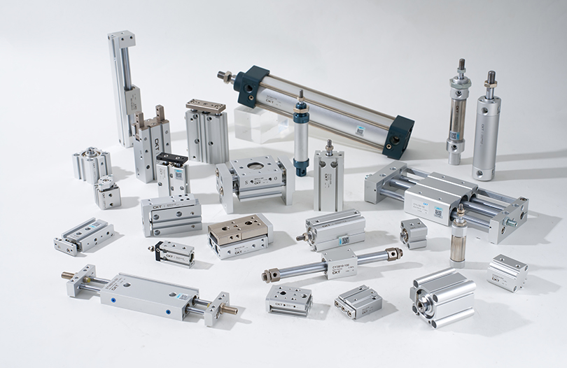
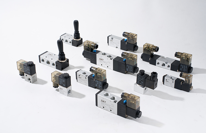
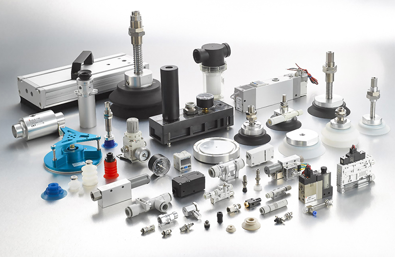
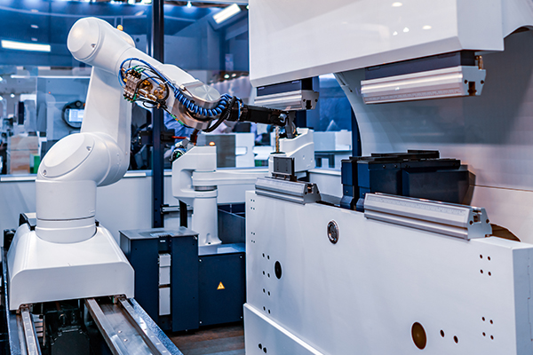
In fields such as industrial automation, mechanical manufacturing, and logistics transportation, pneumatic systems are widely used as a key power source for driving equipment due to their advantages of being clean and pollution-free, fast response speed, and controllable costs. As the "capillaries and nerve endings" of pneumatic systems, pneumatic accessories, although small in individual size, directly determine the stability, safety, and efficiency of the system. Simply put, pneumatic accessories refer to a variety of components that assist pneumatic actuators (cylinders, air motors) and control elements (solenoid valves, directional valves) in realizing their functions, covering the entire process of connection, purification, pressure regulation, lubrication, and silencing.
Classified by function and application scenarios, common pneumatic accessories can be divided into five categories, each with core parameters that require focused attention:
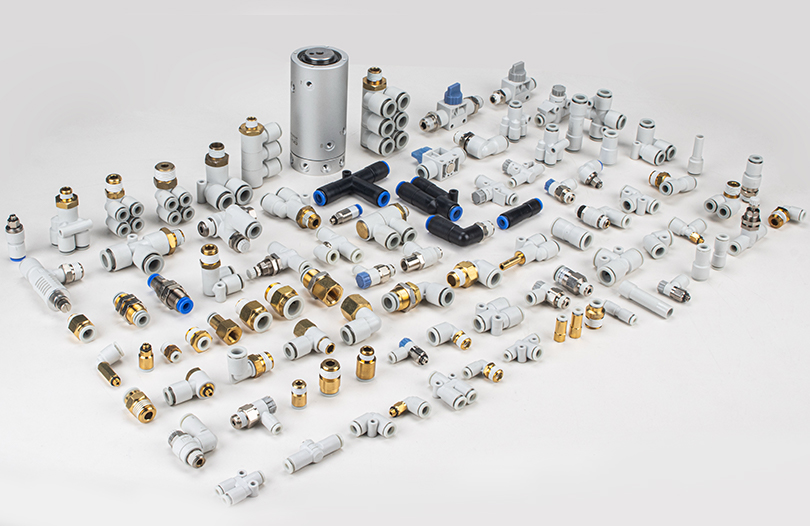
Connection Accessories: Undertake the pipeline connection and gas path switching between pneumatic components, and serve as the foundation for smooth gas flow.
Core Products: Air hoses, quick connectors, pipe fittings, and gas distributors. Air hoses can be divided into polyurethane (PU) air hoses, nylon (PA) air hoses, and polytetrafluoroethylene (PTFE) air hoses based on material. PU air hoses have good flexibility (can be bent repeatedly without breaking) and are suitable for moving parts of equipment (such as robotic arms), with an operating temperature range of -20°C to 80°C. Common inner diameter specifications are 4mm, 6mm, and 8mm, which need to match the flow requirements of the system. Nylon air hoses have high pressure resistance (rated pressure up to 1.6MPa) and strong oil resistance, making them suitable for fixed pipelines (such as the main gas path of equipment). PTFE air hoses are resistant to high and low temperatures (-200°C to 260°C) and strong corrosion, making them suitable for chemical and high-temperature baking equipment.
Quick connectors are available in straight-through, three-way, and elbow types. The core parameters are the interface specification (such as G1/8, G1/4 threads) and rated flow rate. When selecting, it is necessary to ensure compatibility with the inner diameter of the air hose and the interface of the component. For example, a PU air hose with an inner diameter of 6mm should be matched with a quick connector with G1/8 threads to avoid flow loss. Pipe fittings are used for fixed connection between air hoses and components, and attention should be paid to the sealing method (such as O-ring sealing, taper sealing) to prevent leakage.
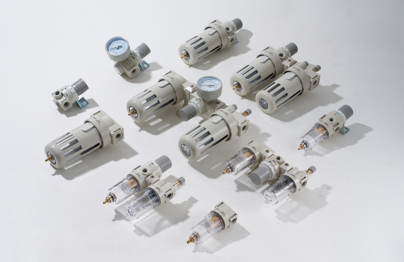
Filtration and Drying Accessories: Purify compressed air, remove impurities such as moisture, oil, and dust, and protect downstream components.
Core Products: Air filters (AF), oil mist separators (AM), refrigerated dryers, and adsorption dryers. The core parameters of air filters are filtration accuracy (5μm, 1μm, 0.01μm) and rated flow rate. A filtration accuracy of 5μm is sufficient for general industrial scenarios, while ultra-precision filtration of 0.01μm is required for precision electronics and pharmaceutical industries. At the same time, attention should be paid to pressure loss (the pressure loss during normal operation should be ≤0.02MPa); excessive pressure loss will lead to insufficient system pressure.
Oil mist separators are used to remove oil from compressed air. The core indicator is the oil mist concentration (the oil mist concentration at the outlet should be ≤0.01mg/m³), which is suitable for oil-free lubrication systems (such as food processing equipment). The core parameter of dryers is the pressure dew point (the pressure dew point of refrigerated dryers can reach 1.7°C, and that of adsorption dryers can reach -40°C). Adsorption dryers should be selected in humid environments or low-temperature areas to prevent pipeline blockage due to freezing.
Pressure Regulation and Lubrication Accessories: Stabilize system pressure, provide lubrication for moving parts, and ensure the normal operation of components.
Core Products: Pressure reducing valves (AR), oil mist lubricators (AL), and booster valves. The core parameters of pressure reducing valves are the pressure regulation range (such as 0.05MPa to 0.8MPa) and pressure stabilization accuracy (±0.02MPa), which should be selected according to the rated pressure of downstream components. For example, if the rated pressure of a cylinder is 0.6MPa, the pressure reducing valve should be adjusted to 0.5-0.6MPa to avoid damage to the cylinder due to excessive pressure.
The core parameters of oil mist lubricators are the oil flow adjustment range (1-5 drops per minute) and applicable oil products (special pneumatic lubricating oil, ISO VG32 or VG46 must be used). Excessive oil flow is likely to contaminate workpieces, while insufficient oil flow fails to achieve the lubrication effect. Oil mist lubricators should be disabled in oil-free systems, and oil-free grease should be used instead.
Silencing and Auxiliary Accessories: Reduce exhaust noise, monitor system status, and improve safety and reliability.
Core Products: Silencers, pressure switches, buffers, and dust caps for pneumatic connectors. The core parameters of silencers are noise reduction (porous silencers can reduce noise by 20-30 decibels) and applicable caliber (which needs to match the exhaust port of the solenoid valve). In scenarios with high dust levels such as woodworking and textile industries, anti-clogging silencers (such as silencers with filter screens) should be selected.
The core parameters of pressure switches are the set pressure range (such as 0.2-1.0MPa) and accuracy (±0.05MPa), which are used to monitor system pressure and send signals when pressure is abnormal to protect equipment. Buffers are installed at both ends of the cylinder, and the core parameter is energy absorption (such as 10J), which reduces the impact at the end of the cylinder's movement and extends the service life of the cylinder.
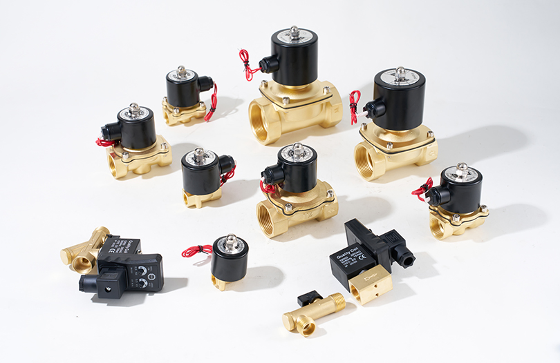
Safety Accessories: Prevent overpressure and accidental startup of the system, and ensure the safety of personnel and equipment.
Core Products: Safety valves, check valves, and emergency stop air valves. The core parameter of safety valves is the set pressure (which should be slightly higher than the system working pressure; for example, if the system working pressure is 0.6MPa, the set pressure is 0.7MPa). When the system pressure exceeds the set pressure, it automatically exhausts to avoid component explosion. Check valves are used to prevent the backflow of compressed air and protect the air compressor or upstream components. Emergency stop air valves can quickly cut off the gas path and stop equipment operation in case of emergency, and should be installed in a position easily accessible to operators.
II. What Hidden Risks Lurk in Pneumatic Accessories? What Are the Easily Overlooked Issues During Use? How to Address the Differences in Risks Across Different Scenarios?
The risks of pneumatic accessories are often "hidden"—initially, they may only manifest as minor leaks or slight noise, but if not addressed in a timely manner, they will gradually develop into system failures and even cause safety accidents. The occurrence of these risks is closely related to improper installation, maintenance, and environmental adaptation, and the risk characteristics vary significantly across different scenarios, requiring targeted solutions.
Common High-Frequency Risks: Problems Caused by Improper Installation and Maintenance
Loose Connections and Seal Failure: Quick connectors that are not fully inserted (such as unlatched buckles), pipe fittings with incompletely tightened threads, or aging sealing rings (such as nitrile rubber rings that harden and crack after long-term use) can lead to compressed air leakage. According to industrial equipment maintenance data, a leak point with a diameter of 6mm can waste compressed air energy equivalent to approximately 1200 kWh of electricity per year under a pressure of 0.6MPa. At the same time, the "hissing" sound caused by leakage increases workshop noise. More seriously, on high-speed moving equipment (such as automated sorting lines), loose connectors may fall off, and air hoses may be entangled with the equipment due to air flow, causing equipment shutdown.
Clogging and Failure of Filtration Components: If the filter element of an air filter is not replaced for a long time (more than 3 months), it will become clogged, increasing the intake resistance and reducing the system pressure, resulting in slow cylinder movement and insufficient output. In severe cases, if the filter element is damaged, unfiltered dust (such as metal shavings and fibers) will enter the solenoid valve, causing the valve core to jam and the solenoid valve to fail to switch normally. It may even scratch the inner wall of the cylinder, causing internal leakage of the cylinder, and the maintenance cost is 8-10 times the cost of replacing the filter element.
Improper Pressure Regulation and Lack of Lubrication: If the pressure adjusted by the pressure reducing valve exceeds the rated pressure of the component (such as adjusting the pressure of a cylinder with a rated pressure of 0.8MPa to 1.0MPa), the cylinder barrel will bear excessive pressure, which is prone to cracks after long-term use. If the oil flow of the oil mist lubricator is adjusted too low or no lubricating oil is added, the piston and cylinder barrel of the cylinder will lack lubrication, accelerating wear and shortening the service life of the cylinder by more than 50%. In oil-free systems, the incorrect use of oil mist lubricators will cause contamination of food and pharmaceutical products, violating industry safety standards (such as GB 14881-2013 National Food Safety Standard for Food Production Sanitation)
Scenario-Specific Risks: Problems Caused by Environmental Factors
Harsh Environments (Mining, Metallurgy, Textile Workshops): Dust, high temperatures, and vibrations are the main sources of risks. Pneumatic accessories of mining equipment are easily clogged by coal dust and ore dust. For example, after the silencer is filled with dust, the exhaust resistance increases, the solenoid valve cannot exhaust smoothly, and the response speed slows down. The high temperature in metallurgical workshops (ambient temperature exceeding 60°C) accelerates the aging of air hoses. PU air hoses soften and crack at high temperatures, leading to gas path leakage. Fiber dust in textile workshops enters the air filter, which can clog the filter element within 1-2 weeks, requiring frequent replacement.
Humid Environments (Food Cleaning Workshops, Aquatic Product Processing Workshops): Moisture is the core risk. Moisture in compressed air condenses in the pipeline. If no dryer is installed, it will cause rusting of pipe fittings, short circuits inside the solenoid valve, and even freezing in low temperatures in winter, blocking the pipeline and causing system paralysis. At the same time, humid environments are prone to mold growth, which adheres to the inner wall of the air hose and contaminates the compressed air, affecting food hygiene and safety.
Precision Environments (Electronic Semiconductor Workshops, Precision Machine Tools): Trace impurities and static electricity are key risks. Even a small amount of oil mist in compressed air (even at a concentration of 0.1mg/m³) can contaminate semiconductor chips, resulting in product scrapping. Static electricity attracts dust, which adheres to the surface of pneumatic accessories and affects component accuracy. For example, after the precision pressure reducing valve is covered with dust, the pressure regulation accuracy decreases, and the pressure cannot be stably controlled, affecting the processing accuracy of the machine tool.
Easily Overlooked "Hidden Risks": Performance Degradation After Long-Term Use
Accessory Aging: Rubber and plastic components of pneumatic accessories, such as air hoses and sealing rings, have a service life. For example, the normal service life of PU air hoses is 2-3 years, after which they will experience decreased elasticity and cracking. Sealing rings will experience permanent compression deformation after long-term use, resulting in reduced sealing performance and leakage.
Parameter Drift: The parameters of components such as pressure reducing valves and pressure switches will drift over time. For example, the pressure stabilization accuracy of the pressure reducing valve changes from ±0.02MPa to ±0.05MPa, leading to system pressure fluctuations and affecting the movement accuracy of equipment. The set value of the pressure switch drifts, which may cause failure to alarm in a timely manner when pressure is abnormal, leading to safety accidents.
III. How to Detect Whether Pneumatic Accessories Are Normal? What Are the Professional and Daily Detection Methods? What Are the Differences in Detection Focus Across Different Accessories?
To detect whether pneumatic accessories are normal, it is necessary to combine "precision inspection with professional tools" and "quick judgment through daily observation", and formulate differentiated detection plans based on the functional characteristics of different types of accessories to ensure timely identification of risks and prevent the expansion of failures.
Professional Detection Tools and Methods: Precise Risk Localization
Leakage Detection: An ultrasonic leak detector is a core tool that can detect tiny leaks that are invisible to the naked eye (minimum detectable leak rate of 0.1mL/min). During detection, place the detector probe near leak-prone parts such as air hose connectors, valve interfaces, and quick connectors. If the display shows a leak rate exceeding 10mL/min (industrial standards require a leak rate ≤10mL/min), mark the location and disassemble for inspection. For large-area leak detection, the "pressure drop method" can be used: close the air source, seal the system outlet, record the initial pressure (such as 0.6MPa), and if the pressure drops by more than 0.02MPa after 30 minutes, it indicates a leak in the system, and each accessory needs to be inspected one by one.
Pressure and Flow Detection: A precision pressure gauge (with an accuracy class of 0.4 or higher) is used to detect the output pressure of the pressure reducing valve and compare it with the set value. If the deviation exceeds ±0.03MPa, adjust the pressure reducing valve or replace the internal spring. A flowmeter (such as a rotameter) is used to detect the pipeline flow rate. If the actual flow rate is less than 80% of the designed value, check whether the filter is clogged or the air hose is bent to eliminate excessive resistance.
Filtration and Drying Effect Detection: A particle counter is used to detect the particle concentration at the outlet of the air filter. For general industrial scenarios, the number of particles ≥0.5μm per cubic meter of air should be ≤10,000, and for precision electronic workshops, it should be ≤1,000. If it exceeds the standard, the filter element needs to be replaced. A dew point meter is used to detect the pressure dew point at the outlet of the dryer. The pressure dew point of refrigerated dryers should be ≤1.7°C, and that of adsorption dryers should be ≤-40°C. If the dew point is too high, check the refrigeration system of the dryer (for refrigerated type) or the adsorbent (for adsorption type).
Lubrication Effect Detection: An oil mist concentration detector is used to detect the oil mist concentration at the outlet of the oil mist lubricator. The normal range is 0.1-0.5mg/m³. If it is too high, reduce the oil flow; if it is too low, add lubricating oil. The lubrication effect can also be judged by observing the movement status of the cylinder. If the cylinder moves with jamming or abnormal noise, it may be due to insufficient lubrication, and the oil mist lubricator needs to be checked.
Daily Detection Methods: Quick Inspection by Operators
"Visual Inspection": Observe the appearance and status of the accessories. The oil level in the oil level gauge of the air filter (in the triple unit) should be maintained between the upper and lower scale lines, and special lubricating oil should be added in a timely manner if it is insufficient. If the water accumulation in the drain valve of the filter exceeds 1/3 of the height of the filter element, manually drain the water (for automatic drain valves, check whether they operate normally). Check whether the air hose has obvious bending, cracking, or aging (such as discoloration and hardening). Check whether the quick connector is fully inserted (whether the buckle is latched and not loose). Check whether the indicator light of the pressure switch is normal (a green light indicates normal, and a red light indicates abnormal pressure).
"Auditory Inspection": Identify whether the operating sound is abnormal. During the normal operation of a pneumatic system, there should only be a stable air flow sound and component movement sound. If a "hissing" leak sound is heard, focus on checking the connectors and valve interfaces. If the solenoid valve makes a "buzzing" abnormal sound, the valve core may be jammed, and it needs to be disassembled and cleaned. If the sound of the silencer suddenly becomes louder (such as from 60 decibels to 80 decibels), it may be internally clogged and needs to be cleaned or replaced. If the cylinder makes an "impact sound", the buffer may be faulty, and the buffer needs to be checked.
"Tactile Inspection": Feel the temperature and vibration of the accessories. Touch the air hose and connector; if there is obvious air flow vibration (not the normal component movement vibration), there may be a leak. Touch the housing of the pressure reducing valve and filter; the normal operating temperature should be similar to the ambient temperature. If it exceeds 40°C (when the ambient temperature is normal), there may be internal blockage or component jamming, and the equipment needs to be shut down for inspection. Touch the cylinder barrel; if the temperature exceeds 50°C, it may be due to insufficient lubrication or excessive pressure, and adjustments are needed.
Detection Focus and Cycles for Different Accessories
Connection Accessories (Air Hoses, Quick Connectors): Focus on detecting leaks and aging.Daily inspection (visual and auditory checks) should be conducted once a day; professional leak detection should be performed once a month. Aging inspection of air hoses should be carried out once every three months (checking elasticity and cracks).
Filtration and Drying Accessories (Filters, Dryers): Focus on detecting filter element clogging and drying effectiveness. Daily inspection (checking filter water accumulation and drain valve operation) should be done once a day; professional particle counting and dew point detection should be conducted once every three months. Filter elements should be replaced every 3-6 months (or earlier in harsh environments).
Pressure Regulation and Lubrication Accessories (Pressure Reducing Valves, Oil Mist Lubricators): Focus on detecting pressure stability and oil quantity. Daily pressure observation (checking pressure gauge readings) should be done once a day; professional pressure calibration should be performed once every six months. Oil quantity inspection of oil mist lubricators should be conducted once a week, and oil should be added in a timely manner if insufficient.
Safety Accessories (Safety Valves, Emergency Stop Air Valves): Focus on detecting functional effectiveness. Daily testing of emergency stop air valves (checking if the air path is cut off when activated) should be done once a day; safety valves should be sent to qualified institutions for calibration once a year (in accordance with national standards such as GB/T 12243-2005 Spring-Loaded Safety Valves)
IV. How to Maintain and Use Pneumatic Accessories Correctly? What Are the Scenario-Specific Recommendations? How to Avoid Common Misconceptions in Maintenance?
Proper maintenance and use are essential for extending the service life of pneumatic accessories and ensuring system safety. A standardized process should be developed based on the characteristics of the accessories and the usage scenario, while common misconceptions should be avoided to prevent problems caused by improper operation.
General Maintenance Process: Standardized Operations to Reduce Errors
Maintenance of Filtration Accessories: Air filter elements should be replaced regularly—every 3-6 months for general industrial scenarios, and every 1-2 months for harsh environments (high dust, high humidity). When replacing the filter element, first close the air source, release the pressure in the pipeline, disassemble the filter housing, remove the old filter element, install the new filter element (ensuring the seal is intact: no damage to the O-ring, proper installation), then turn on the air source and check for leaks. Maintenance of dryers: For refrigerated dryers, clean the condenser every six months (blow off dust with compressed air or rinse with water), and replace the refrigerant every year if cooling efficiency decreases. For adsorption dryers, replace the adsorbent (such as activated alumina) every 1-2 years; when replacing, empty the system to prevent the adsorbent from getting damp.
Maintenance of Connection Accessories: When installing air hoses, reserve a sufficient bending radius (e.g., a minimum bending radius of 20mm for 4mm inner diameter air hoses, 30mm for 6mm inner diameter) to avoid cracking due to excessive bending. When inserting or removing quick connectors, first close the air source—do not insert or remove under pressure (to prevent damage to the seal). Regularly inspect the sealing rings of connectors; if deformation or aging is found, replace them with seals of the same model and material (e.g., nitrile rubber seals for general environments, fluororubber seals for high-temperature and corrosive environments). Clean dust and oil from the surface of air hoses regularly (wipe with a dry cloth) to prevent corrosion.
Maintenance of Pressure Regulation and Lubrication Accessories: Pressure reducing valves should be calibrated regularly—once every six months using a precision pressure gauge. Calibration steps: Close downstream components, adjust the pressure reducing valve to the set value (e.g., 0.6MPa), observe the reading of the precision pressure gauge; if the deviation exceeds ±0.03MPa, adjust the adjusting screw of the pressure reducing valve until the pressure is stable. Oil mist lubricators should use special pneumatic lubricating oil (do not use engine oil or gear oil); the oil quantity should be adjusted to 1-3 drops per minute. If the system is out of service for a long time (more than one month), drain the lubricating oil from the oil mist lubricator to prevent deterioration. When restarting, add new oil and slowly turn on the air source to avoid a sudden increase in oil quantity.
Maintenance of Safety Accessories: Safety valves should be sent to qualified institutions for calibration once a year (in accordance with national standards) to ensure accurate set pressure (e.g., if the system operating pressure is 0.6MPa, the set pressure should be 0.7MPa). After passing calibration, affix a qualification label. During daily inspection, check if the lead seal of the safety valve is intact (no damage or tampering); if the lead seal is broken, immediately take it out of service and re-calibrate. Emergency stop air valves should be tested daily before operation (press the emergency stop button to check if the air path is completely cut off—verify with a pressure gauge that the downstream pressure is 0, and that the equipment stops running). After testing, reset the emergency stop button to ensure it is ready for use.
Scenario-Specific Maintenance Recommendations
Harsh Environments (Mining, Metallurgy, Textile Workshops): The core focus is "pollution prevention and resistance to high/low temperatures". For pneumatic accessories of mining equipment, install dust shields (such as dust caps for quick connectors, protective covers for filter housings) to prevent direct dust intrusion. After daily operation, blow off dust from the surface of accessories with compressed air (pressure ≤0.3MPa) to prevent accumulation and blockage. For metallurgical workshops, select high-temperature-resistant accessories, such as fluororubber seals and PTFE air hoses, instead of ordinary PU air hoses. Install air hoses away from high-temperature equipment (such as furnaces); if necessary, add heat-insulating sleeves to reduce the impact of ambient temperature on the accessories. For textile workshops, shorten the filter element replacement cycle to 1-2 weeks, and install a pre-filter (50μm precision metal mesh filter element) at the air inlet of the filter to intercept large fiber particles first, reducing the load on the main filter element. Select metal mesh self-cleaning silencers, and blow them backward with compressed air once a week to remove internal fibers.
Humid Environments (Food Cleaning Workshops, Aquatic Product Processing Workshops): The key focus is "moisture prevention, rust prevention, and pollution prevention". All pneumatic accessories should be made of rust-resistant materials, such as 316 stainless steel connectors and aluminum alloy filter housings (with anodized surfaces), to avoid rust on carbon steel accessories. The system must be equipped with an adsorption dryer (pressure dew point ≤-20°C), and a precision filter (1μm precision) should be installed after the dryer to further remove moisture and impurities. After daily operation, drain the compressed air from the pipeline to prevent moisture condensation due to temperature drops at night. Regularly (once a month) clean the surface of air hoses and connectors with a neutral cleaning agent (such as diluted food-grade dish soap) to prevent oil and food residue from adhering and causing mold growth. In food contact areas, do not use ordinary lubricating oil—use food-grade grease (compliant with FDA certification), and adjust the oil mist lubricator to the minimum oil quantity (1 drop per minute) to reduce lubrication pollution risks.
Precision Environments (Electronic Semiconductor Workshops, Precision Machine Tools): The core focus is "impurity control and static prevention". The compressed air system should adopt a "three-stage filtration + oil-free drying" configuration: pre-filter (10μm precision) → refrigerated dryer → precision filter (1μm precision) → ultra-precision filter (0.01μm precision), to ensure the oil mist concentration at the outlet is ≤0.001mg/m³ and the particle concentration is ≤100 particles/m³ (for particles ≥0.1μm). All accessories should be made of anti-static materials, such as conductive PU air hoses (surface resistance ≤10^9Ω) and anti-static connectors, to avoid static adsorption of dust. Install air hoses to avoid friction with metal parts of the equipment to reduce static generation. Regularly (once a week) clean the surface of accessories with an anti-static cloth—do not use ordinary rags (which easily generate static). Precision pressure reducing valves for precision machine tools should be high-precision models (pressure stabilization accuracy ±0.01MPa), and re-calibrated with a calibrator once every three months to ensure pressure stability and avoid pressure fluctuations affecting processing accuracy.
Common Misconceptions in Maintenance and How to Avoid Them
Misconception 1: "Accessories only need to be replaced when broken; daily maintenance is unnecessary." Some operators believe that pneumatic accessories have a simple structure and do not require regular maintenance, and only replace them when faults occur, leading to fault expansion. For example, if a filter element is not replaced in time when clogged, it will cause insufficient system pressure, which in turn slows down cylinder movement and affects production efficiency; in severe cases, it may cause the solenoid valve core to jam, resulting in significantly increased maintenance costs.
Avoidance Method: Establish a "preventive maintenance system", develop a maintenance schedule based on the type of accessory and usage scenario (such as the inspection cycles mentioned earlier), clarify the maintenance responsible person and operation process, and record maintenance activities regularly (such as filter element replacement dates, pressure calibration data) to ensure maintenance is standardized and regular.
Misconception 2: "Randomly mix accessories of different brands and models." To save time, some users do not consider model compatibility when replacing accessories—for example, using ordinary PU air hoses instead of high-temperature-resistant air hoses, or using G1/4 threaded connectors instead of G1/8 threaded ones—leading to leaks, insufficient flow, and other problems. For example, forcing a G1/4 connector to fit a solenoid valve with a G1/8 interface will cause severe leaks due to mismatched seals, and may even damage the interface threads.
Avoidance Method: Before replacing an accessory, check the model and specifications of the original accessory (such as air hose inner diameter, connector thread, rated pressure), and prioritize products of the same brand and model. If replacing with a different brand, consult the manufacturer's technical staff to confirm that the interface size, sealing method, and pressure rating are fully compatible before use. After replacement, perform a leak test to ensure no abnormalities.
Misconception 3: "Any lubricating oil can be used as long as it provides lubrication." Some users are unaware of the lubrication requirements of pneumatic systems and use engine oil or gear oil instead of special pneumatic lubricating oil, leading to clogging of the oil mist lubricator and accelerated aging of seals. For example, additives in engine oil can corrode polyurethane seals, causing them to swell and crack, and shortening the service life of accessories.
Avoidance Method: Strictly use special pneumatic lubricating oil (ISO VG32 or VG46)—do not use other types of oil. Before adding lubricating oil, check the oil level gauge of the oil mist lubricator to ensure the oil has not deteriorated (e.g., no turbidity or odor). Clean the oil tank of the oil mist lubricator regularly (once every three months) to remove impurities from the bottom and prevent blockage of the oil path.
Misconception 4: "Safety valves do not need calibration; they are fine as long as they can exhaust." Some users ignore the calibration of safety valves, believing that they are normal as long as they can exhaust when pressure is high, leading to drift of the safety valve set pressure and failure to provide safety protection. For example, if the set pressure of a safety valve drifts from 0.7MPa to 0.9MPa, the safety valve will not operate when the system pressure abnormally rises to 0.8MPa, potentially causing the cylinder to burst.
Avoidance Method: Strictly follow national standards (such as GB/T 12243-2005 Spring-Loaded Safety Valves), and send safety valves to qualified third-party institutions for calibration once a year. After passing calibration, affix a qualification label and the next calibration date. During daily inspection, do not adjust the set pressure of the safety valve or damage the lead seal without authorization; if the lead seal is broken, immediately take it out of service and re-calibrate.
V. What Are the Emergency Handling Methods for Pneumatic Accessory Failures? How to Quickly Address Different Types of Failures?
Pneumatic accessories may experience sudden failures during use (such as leaks, blockages, abnormal pressure), which can lead to equipment shutdown, production interruptions, or even safety accidents if not addressed promptly. Mastering quick emergency handling methods can minimize losses and ensure the safety of personnel and equipment.
Leakage Failures: Quickly Block the Air Source to Prevent Risk Expansion
Common Scenarios: Air hose cracking, connector leakage, valve seal failure—manifested by a "hissing" air flow sound and rapid pressure drop in the system.
Emergency Steps:
Immediately close the air source valve upstream of the faulty accessory (such as a branch pipeline shut-off valve) to cut off the air supply and prevent continuous leakage of compressed air. If the branch valve cannot be found, close the main system air source valve (ensure this does not affect other critical equipment).
Observe the location and severity of the leak: If the air hose is cracked, cut off the damaged section with scissors, reconnect the remaining air hose (ensure sufficient length to avoid bending), and temporarily secure it with cable ties. If the leak is at a connector, disassemble the connector and check if the seal is damaged; if the seal is intact, re-tighten the connector (apply special pneumatic sealant to threaded connectors—do not use Teflon tape to avoid blocking the air path); if the seal is damaged, replace it with a spare seal before reinstalling.
Before restoring the air supply, apply soapy water to the leak point to confirm no bubbles appear, then slowly turn on the air source to avoid secondary leakage due to sudden pressure increases. After turning on the air source, observe the system pressure to ensure it remains stable within the normal range.
Notes: Wear protective gloves when handling leaks to avoid hand injuries from high-speed air flow. If the leak is near electrical equipment, first cut off the power supply to prevent short circuits caused by compressed air coming into contact with electrical components.
Blockage Failures: Quickly Clean or Temporarily Replace to Restore Air Path Smoothness
Common Scenarios: Filter element clogging, silencer clogging, air hose bending—manifested by insufficient system pressure, slow cylinder movement, and abnormal exhaust noise.
Emergency Steps:
If the filter element is clogged (indicated by discoloration of the filter element and pressure gauge reading drop), close the air source, disassemble the filter housing, remove the old filter element, and blow it backward with compressed air (pressure ≤0.3MPa); if clogging is severe and cannot be cleaned, replace it with a spare filter element. After installation, turn on the air source and check if the pressure has returned to normal.
If the silencer is clogged (indicated by increased exhaust noise and poor solenoid valve exhaust), close the air source, disassemble the silencer, and clean internal dust with compressed air (or rinse with water and dry before use); if the silencer is damaged, replace it with a spare silencer of the same caliber.
If the air hose is bent (indicated by obvious deformation of the air hose and poor air flow), close the air source, adjust the air hose routing to eliminate bending, or replace it with a new air hose (ensure sufficient length to avoid re-bending). After installation, turn on the air source and check if the cylinder movement has returned to normal.
Notes: When cleaning blockages, avoid impurities falling into the air path (e.g., cover the interface with a clean cloth when disassembling the filter). After replacing accessories, perform a flow test to ensure the air path is smooth.
Abnormal Pressure Failures: Quickly Adjust or Cut Off the Air Source to Prevent Equipment Damage
Common Scenarios: Pressure reducing valve failure (excessive or insufficient pressure), pressure switch malfunction—manifested by continuous increase or decrease in system pressure, and abnormal equipment movement (e.g., excessive cylinder thrust, inability to move).
Emergency Steps:
If the pressure reducing valve pressure is excessive (exceeding the rated pressure of the component), immediately close the air source, disassemble the pressure reducing valve, and check if the internal spring is broken or the valve core is jammed; if the spring is broken, replace it with a spare pressure reducing valve; if the valve core is jammed, clean it with a special cleaner (such as pneumatic system cleaner), dry it, and reinstall it. After installation, slowly adjust the pressure to the normal range and calibrate it with a precision pressure gauge.
If the pressure reducing valve pressure is insufficient (cannot reach the set value), check if the filter is clogged (if so, address it as a blockage failure) or if the internal seal of the pressure reducing valve is aging; if the seal is aging, replace the seal and re-adjust the pressure. If the problem persists, replace it with a spare pressure reducing valve.
If the pressure switch malfunctions (fails to alarm when pressure is abnormal), immediately close the main system air source valve, replace it with a spare pressure switch, and test its function after installation (adjust the system pressure to around the set value to check if the switch operates normally). Faulty pressure switches should be repaired or discarded—do not continue using them.
Notes: Do not force-start equipment when pressure is abnormal to prevent component overload damage. When adjusting pressure, slowly turn the adjusting screw to avoid sudden pressure increases or decreases.
Safety-Related Failures: Prioritize Personnel Safety and Cut Off Risk Sources
Common Scenarios: Safety valve failure (to operate), emergency stop air valve failure—manifested by the safety valve failing to exhaust when system pressure exceeds the rated value, or the equipment failing to stop when the emergency stop button is pressed.
Emergency Steps:
If the safety valve fails to operate (system pressure rises abnormally), immediately turn off the air compressor power supply to cut off the air source supply; at the same time, open the system vent valve (if available) to slowly release the system pressure. After the pressure drops to a safe range, replace the safety valve with a calibrated spare one—do not continue using the faulty safety valve.
If the emergency stop air valve fails (the equipment does not stop after pressing), immediately close the main system air source valve to force the equipment to stop. Check if the emergency stop air valve core is jammed or the wiring is loose; if the core is jammed, replace it with a spare emergency stop air valve; if the wiring is loose, reconnect the wiring and test the function. Only after confirming the emergency stop air valve is normal can the equipment be restarted.
Notes: When handling safety-related failures, first evacuate personnel around the equipment and set up warning signs to prevent unrelated personnel from approaching. Do not put the equipment into use until the fault is resolved; it can only be restarted after being confirmed safe by professional personnel.
VI. What Are the Core Principles for Selecting Pneumatic Accessories? How to Avoid Pitfalls for Different Needs?
Selection is the "first step" in using pneumatic accessories. If the selection is incorrect, even perfect subsequent maintenance cannot avoid failures. It is necessary to adhere to the three core principles of "compatibility, safety, and economy", and make comprehensive judgments based on system requirements, environmental characteristics, and usage frequency, while avoiding common selection pitfalls.
Core Selection Principles: Accurate Matching with System Requirements
Principle 1: Pressure and flow matching to avoid "underpowered operation" or "over-specification waste". First, clarify the maximum operating pressure of the system (e.g., 0.6MPa); the rated pressure of all accessories must be ≥1.2 times the maximum system pressure (i.e., select accessories with a rated pressure ≥0.72MPa) to prevent damage due to pressure overload. Second, select the appropriate air hose and connector diameter based on the air consumption of the pneumatic components, with reference to the table below for accurate matching:
|
Air Hose Type |
Inner Diameter (mm) |
Maximum Flow Rate (L/min, at 0.6MPa) |
Suitable Air Consumption of Components (L/min) |
Typical Application Scenarios |
|
PU Air Hose |
4 |
60 |
≤50 |
Small cylinders, pneumatic fingers |
|
PU Air Hose |
6 |
120 |
50-100 |
Medium cylinders, pneumatic grippers |
|
PU Air Hose |
8 |
200 |
100-180 |
Large cylinders, air motors |
|
Nylon Air Hose |
10 |
300 |
180-280 |
Heavy-duty pneumatic equipment |
Principle 2: Environmental adaptability first, avoiding "one-size-fits-all" selection. Different environments require accessories of specific materials to avoid failures caused by material incompatibility, with reference to the table below for selection:
|
Usage Environment |
Recommended Accessory Materials |
Tolerance Range |
Prohibited Materials |
Typical Application Scenarios |
|
High-temperature (80-120℃) |
PTFE air hoses, fluororubber seals |
-200℃ to 260℃ |
Ordinary PU air hoses, nitrile rubber |
Metallurgical baking equipment, welding robots |
|
Corrosive (acid/alkali) |
316 stainless steel connectors, PVC air hoses |
pH 2-12 |
Carbon steel connectors, ordinary rubber |
Chemical reactors, acid washing equipment |
|
Food/pharmaceutical industry |
Silicone air hoses, 304 stainless steel connectors |
FDA-compliant, non-toxic, odorless |
PVC air hoses with plasticizers |
Food cleaning machines, pharmaceutical filling equipment |
|
Humid (humidity ≥80%) |
Galvanized connectors, water-resistant PU air hoses |
IP65 waterproof rating |
Unrusted carbon steel connectors |
Aquatic processing equipment, bathroom pneumatic devices |
Principle 3: Matching usage frequency with service life to balance cost and durability. High-frequency usage scenarios require high-durability accessories, while low-frequency scenarios can prioritize cost-effectiveness, with reference to the table below for selection:
|
Usage Frequency (Times/Hour) |
Recommended Accessory Type |
Expected Service Life (Years) |
Cost Level |
Typical Application Scenarios |
|
≥100 (High-frequency) |
Metal-shell quick connectors, fatigue-resistant PU air hoses |
3-5 |
Medium-high |
Automated production lines, sorting robots |
|
10-100 (Medium-frequency) |
Reinforced plastic connectors, ordinary PU air hoses |
2-3 |
Medium |
Semi-automated equipment, manual pneumatic tools |
|
≤10 (Low-frequency) |
Ordinary plastic connectors, nylon air hoses |
1-2 |
Low |
Manually controlled valves, temporary pneumatic devices |
Common Selection Pitfalls and Avoidance Methods
Pitfall 1: "The larger the diameter, the better; sufficient flow is guaranteed." Some users believe that larger air hose and connector diameters ensure sufficient flow, and blindly select large specifications, leading to installation difficulties (e.g., 6mm air hoses cannot pass through narrow equipment spaces) and increased costs (large-specification accessories are 30%-50% more expensive than small-specification ones).
Avoidance Method: Select the diameter based on the "suitable air consumption of components" in the table above. It is sufficient to ensure the accessory diameter meets the component's flow requirements; there is no need for over-specification. If space is limited, select "thin-walled large-flow air hoses" (e.g., thin-walled PU air hoses with 6mm inner diameter and 8mm outer diameter) to ensure flow within limited space.
Pitfall 2: "Only focus on price; cheaper is better." Low-priced accessories often cut corners in materials and craftsmanship—such as using recycled plastic for air hoses (prone to cracking) or ordinary carbon steel for connectors (prone to rust). Although they seem cost-effective in the short term, frequent replacements (with a service life only 1/3 that of high-quality accessories) increase long-term costs.
Avoidance Method: Prioritize products from branded and qualified manufacturers (e.g., those with ISO9001 certification) and check product test reports (e.g., material composition, rated pressure test data). Compare accessory service lives (e.g., high-quality PU air hoses have a service life of 3-5 years, while low-priced ones have 1-2 years) and calculate the "cost per unit time" instead of just the one-time purchase price.
Pitfall 3: "Ignore interface compatibility; buy first and worry later." Some users fail to confirm accessory interface specifications when purchasing—for example, buying G1/4 threaded connectors for solenoid valves with G1/8 interfaces—resulting in installation failures and the need for re-purchasing, wasting time and costs.
Avoidance Method: Before purchasing, record the interface specifications of downstream components (e.g., thread type: G-thread, NPT thread; interface size: 1/8, 1/4) or bring the old accessory for comparison. For online purchases, provide the component model to the customer service and confirm full compatibility of the accessory interface before placing an order.
VII. Standard Installation Processes and Correction of Common Errors for Pneumatic Accessories
Installation is the "critical link" for pneumatic accessories to function properly. Improper installation directly leads to leaks, pressure loss, and shortened service life. It is necessary to follow the three-step process of "preparation-installation-acceptance" while correcting common installation errors to ensure stable compatibility between accessories and the system.
Pre-Installation Preparation: Lay the Foundation to Avoid Blind Operation
Step 1: Environment and tool preparation. Clean the installation area to remove dust, oil, and debris (especially in precision environments, wipe the installation surface with a dust-free cloth). Prepare special tools: pipe cutters (for cutting air hoses, avoiding uneven cuts from ordinary scissors), torque wrenches (for tightening threaded connectors to prevent over-tightening or under-tightening), pneumatic-specific sealant (do not use Teflon tape), and dust-free, fiber-free cleaning cloths (for wiping accessory interfaces).
Step 2: Accessory and system inspection. Verify that the accessory model and specifications match the design (e.g., air hose inner diameter, connector thread, rated pressure). Check that the accessory appearance is intact, with no cracks, deformation, or missing seals (e.g., no O-ring falling off from quick connectors). Check that the pneumatic system pipeline is clean; purge the pipeline interior with compressed air (pressure ≤0.3MPa) to remove iron filings, dust, and other impurities and prevent post-installation accessory blockage.
Step 3: Safety protection preparation. Wear protective equipment: anti-slip gloves (to prevent accessory slippage) and safety goggles (to prevent eye injuries from impurities blown by compressed air). If the system is already pressurized, first close the main air source valve and release residual pressure in the pipeline (confirm pressure is 0 with a pressure gauge) to avoid accessory ejection during installation.
Standard Installation Steps for Core Accessories
(1) Air Hose Installation:
Cut the air hose: Use a pipe cutter to cut the air hose vertically, ensuring a flat cut (no burrs or inclinations). An uneven cut will cause poor sealing with the connector and lead to leaks. After cutting, wipe the cut with a cleaning cloth to remove plastic debris.
Insert into the connector: Fully insert the air hose into the quick connector or pipe fitting interface until a "click" sound is heard (for quick connectors) or the air hose touches the internal stop ring of the pipe fitting (for pipe fittings). For quick connectors with latches, fasten the latch to prevent the air hose from falling off.
Secure the pipeline: After installation, secure the air hose with cable ties to avoid suspension or friction with moving equipment parts. The securing spacing depends on the air hose inner diameter: secure 4-6mm air hoses every 30cm and 8-10mm air hoses every 50cm. At the same time, reserve a sufficient bending radius (e.g., ≥20mm for 4mm air hoses, ≥30mm for 6mm air hoses) and prohibit excessive bending.
(2) Threaded Connector Installation:
Apply sealant: Evenly apply pneumatic-specific sealant to the external thread of the connector (not the sealing surface), with a thickness of approximately 0.1-0.2mm. Apply sealant to only 3-4 threads; excessive sealant will enter the air path and block accessories.
Tighten the connector: Tighten using a torque wrench according to the specified torque. The standard torque for threaded connectors of different specifications is shown in the table below. Prohibit over-tightening by hand to prevent thread damage or seal deformation. After tightening, check that the connector is vertical and not inclined.
|
Thread Specification |
Thread Type |
Standard Tightening Torque (N·m) |
Allowable Deviation (±N·m) |
Suitable Sealant Type |
Recommended Tightening Tool |
|
1/8 |
G-thread |
10-12 |
1 |
Pneumatic-specific anaerobic sealant |
1/4-inch torque wrench |
|
1/4 |
G-thread |
15-18 |
1.5 |
Pneumatic-specific anaerobic sealant |
1/4-inch torque wrench |
|
3/8 |
G-thread |
25-30 |
2 |
Pneumatic-specific anaerobic sealant |
3/8-inch torque wrench |
|
1/2 |
G-thread |
40-45 |
3 |
Pneumatic-specific anaerobic sealant |
1/2-inch torque wrench |
(3) Filter and Pressure Reducing Valve (Triple Unit) Installation:
Determine the installation direction: Install the filter vertically with the drain port facing downward for easy drainage. Install the pressure reducing valve horizontally with the adjustment knob facing upward for easy operation. Install the triple unit (filter + pressure reducing valve + oil mist lubricator) in the order of "air inlet → filtration → pressure regulation → lubrication"; do not reverse the order.
Secure and connect: Fix the triple unit to the equipment bracket with a bracket to avoid accessory loosening due to vibration. When connecting the pipeline, connect the inlet end to the upstream air source and the outlet end to downstream components. Ensure the air flow direction matches the accessory mark (e.g., arrow direction).
Post-Installation Acceptance Standards and Detection Methods
Visual Acceptance: Accessories are securely installed with no loosening or inclination. Air hoses have no bending or twisting and are evenly secured. Threaded connectors have no exposed threads (except for specified lengths) and no sealant overflow. Accessory marks are clear and the air flow direction is correct.
Leakage Detection: Turn on the air source and adjust the system pressure to the operating pressure (e.g., 0.6MPa). Apply soapy water to all connectors and interfaces and observe for 5 minutes; no bubbles indicate qualification. Alternatively, use an ultrasonic leak detector for detection; a leak rate ≤10mL/min indicates qualification.
Functional Detection: Test whether the accessory functions are normal. For example, adjust the pressure reducing valve and observe whether the pressure gauge reading is stable (fluctuation ≤±0.02MPa). Start the downstream cylinder and check whether the movement is smooth with no jamming or delay. Test the filter drain valve and check whether drainage is smooth when the drain button is pressed.
Common Installation Errors and Correction Methods
Error 1: Inclined air hose cut leading to poor sealing. Some users cut air hoses obliquely with ordinary scissors, resulting in a cut angle exceeding 5° with the air hose axis. After installation, the cut cannot fully fit the connector sealing surface, leading to leaks.
Correction Method: Must use a pipe cutter for vertical cutting. After cutting, check the cut perpendicularity with a square to ensure the angle ≤2°. If an inclined cut occurs, re-cut and do not force installation.
Error 2: Over-tightening threaded connectors leading to seal damage. Some users believe "the tighter the better for sealing" and over-tighten with a wrench, causing thread damage or seal over-compression and instead leading to leaks.
Correction Method: Strictly follow the "standard tightening torque" in the table above. If no torque wrench is available, judge by "hand feel": after feeling resistance during tightening, gently tighten an additional 1/4 turn to avoid excessive force.
Error 3: Using Teflon tape instead of sealant leading to air path blockage. Some users are accustomed to using Teflon tape to seal threaded connectors. Teflon tape fibers easily fall off and enter solenoid valves and cylinders with air flow, causing valve core jamming and cylinder wear.
Correction Method: Immediately replace with pneumatic-specific sealant. If Teflon tape has already been used, disassemble the connector, clean residual Teflon tape, purge the pipeline with compressed air, and re-install with sealant.
Error 4: Filter drain port facing upward leading to inability to drain. Some users ignore the direction when installing the filter, with the drain port facing upward. This causes water accumulation inside the filter to be unable to drain, and moisture enters downstream accessories with air flow, accelerating component aging.
Correction Method: Disassemble the filter and adjust the installation direction to ensure the drain port faces vertically downward. If installation space is limited, use a drain connector with an elbow to indirectly change the drain direction, but ensure smooth drainage.
VIII. Scrap Standards and Green Disposal Methods for Pneumatic Accessories
When pneumatic accessories reach the end of their service life, continued use will pose safety risks, so clear scrap standards are necessary. At the same time, green disposal methods should be adopted to reduce resource waste and environmental pollution, in line with the requirements of industrial sustainable development.
Scrap Standards for Pneumatic Accessories
(1) Safety Scrap: Accessories must be scrapped immediately and prohibited from continued use if any of the following conditions occur. Specific judgment standards are shown in the table below:
|
Scrap Type |
Judgment Indicators |
Detection Method |
Risk Consequences |
|
Structural Damage |
Air hose crack length ≥5mm or breakage; ≥2 stripped threads on connector; safety valve body deformation |
Visual inspection, thread gauge detection |
Air hose burst, gas leakage, pressure loss |
|
Performance Exceedance |
Filter element damage with filtration accuracy reduced by >50%; pressure reducing valve pressure stabilization accuracy >±0.05MPa; quick connector leak rate >50mL/min |
Particle counter, pressure gauge, ultrasonic detector |
Component jamming, abnormal equipment movement, increased energy consumption; decreased temperature resistance (softening in high-temperature environments) |
|
Material Aging |
Seal hardness increased by >30% or cracking; air hose unable to recover after bending |
Hardness tester, bending test, high-temperature test |
Seal failure, air hose rupture, contaminant intrusion |
(2) Economic Scrap: If the maintenance cost of an accessory exceeds 50% of the price of a new accessory, or its remaining service life is less than 3 months, it is recommended to scrap and replace it to avoid frequent maintenance affecting production efficiency. For example, a pressure reducing valve used for 3 years requires replacement of internal springs and seals, with maintenance costs accounting for 60% of the price of a new valve, and its service life after maintenance is only 2 months—such an accessory should be directly scrapped.
Green Disposal Methods for Accessories
(1) Classified Recycling: Dispose of accessories according to their material types. Metal accessories (such as stainless steel connectors and brass quick connectors) should be sent to metal recycling stations for smelting and reuse; plastic accessories (such as PU air hoses and plastic connectors) should be sent to plastic recycling enterprises for processing into recycled plastic; seals (such as rubber O-rings) made of non-toxic materials can be sent to rubber recycling plants, while those containing harmful substances (such as fluororubber) should be treated as hazardous waste and handed over to qualified institutions for disposal.
(2) Resource Reutilization: Recyclable parts of some accessories can be disassembled for reuse. For example, undamaged metal housings of filters can be cleaned and re-equipped with new filter elements; intact metal latches of quick connectors can be reused after replacing new sealing rings, reducing resource waste.
(3) Environmental Protection Disposal: It is prohibited to discard accessories randomly, especially those containing toxic and harmful substances (such as lead-containing sealants and fluorine-containing air hoses). These should be collected uniformly and handed over to waste disposal institutions recognized by local environmental protection departments for harmless treatment in accordance with national standards to prevent soil and water pollution.
Supplementary Summary: The "Full-Life-Cycle Thinking" in Pneumatic Accessory Management
The management of pneumatic accessories should run through the "full life cycle" from selection, installation, maintenance, and emergency handling to scrapping: in the selection stage, accurately match requirements to avoid inherent defects; in the installation stage, standardize operations to lay a solid foundation for use; in the maintenance stage, conduct preventive maintenance to extend service life; in the emergency handling stage, respond scientifically to reduce fault losses; in the scrapping stage, conduct compliant disposal to practice the concept of green development.
At the same time, digital tools can be used to improve management efficiency. For example, establish an "electronic ledger" for pneumatic accessories to record accessory models, purchase dates, maintenance records, and scrapping dates; attach "QR codes" to key accessories, allowing users to view maintenance guidelines, installation specifications, and historical records by scanning the code. By combining full-life-cycle management with digital means, it is possible to reduce the failure rate, optimize costs, ensure production safety, and promote green production, enabling pneumatic accessories to continue to contribute to industrial production.


