


Content
- 1 I. What Exactly Are Process Valves? What Role Do They Play in Industrial Processes?
- 2 II. What Are the Common Types of Process Valves? What Are the Differences in Their Applicable Scenarios?
- 2.1 1. Gate Valves: Why Are They Often Used in "Fully Closed" or "Fully Open" Scenarios?
- 2.2 2. Ball Valves: Why Are They the First Choice in Fast Switching Scenarios?
- 2.3 3. Globe Valves: What Advantages Do They Have in Flow Regulation Scenarios?
- 2.4 4. Safety Valves: The "Safety Barrier" of Industrial Systems—What Is Their Working Principle?
- 3 III. How to Properly Maintain Process Valves? Which Maintenance Details Can Extend Their Service Life?
- 4 IV. What Mistakes Are Easily Made When Selecting Process Valves? How to Avoid Them?
- 5 V. What Are the Key Precautions for Process Valve Installation? What Problems Can Incorrect Installation Cause?
- 6 VI. How to Handle Process Valve Failures in Different Working Conditions?
- 6.1 1. Valve Failures in Flammable and Explosive Fluid Pipelines: Prioritize Isolating Hazard Sources (with Detailed Operation Process)
- 6.2 2. Valve Failures in High-Temperature and High-Pressure Fluid Pipelines: Prevent Burns and Equipment Damage (with Protection and Pressure Relief Standards)
- 6.3 3. Valve Failures in Corrosive Fluid Pipelines: Prevent Corrosion Spread (with Neutralization and Cleaning Standards)
- 7 VII. What Should Be Focused on During Daily Inspections of Process Valves? Keep This Inspection Checklist Handy
- 8 VIII. Decommissioning and Replacement of Process Valves: How to Scientifically Determine Replacement Timing?
- 9 IX. Conclusion: Building a Full-Lifecycle Management System for Process Valves
In industrial fields such as petrochemicals, water treatment, and energy production, Process Valves act like "valves in blood vessels," regulating every flow of fluid. Industry data shows that in a complete industrial production system, the number of Process Valves can reach hundreds or even thousands. Their operating status directly affects production efficiency (valve failures can reduce production efficiency by more than 30%) and safety (approximately 40% of industrial safety accidents are related to valve leakage or failure). However, most practitioners still perceive them only as "switching tools," ignoring the complex technical logic and operation and maintenance essentials behind them. This article will comprehensively break down the core knowledge of Process Valves from the perspectives of definition, types, selection, installation, emergency handling, and daily inspection, providing practical guidance for industrial production.
I. What Exactly Are Process Valves? What Role Do They Play in Industrial Processes?
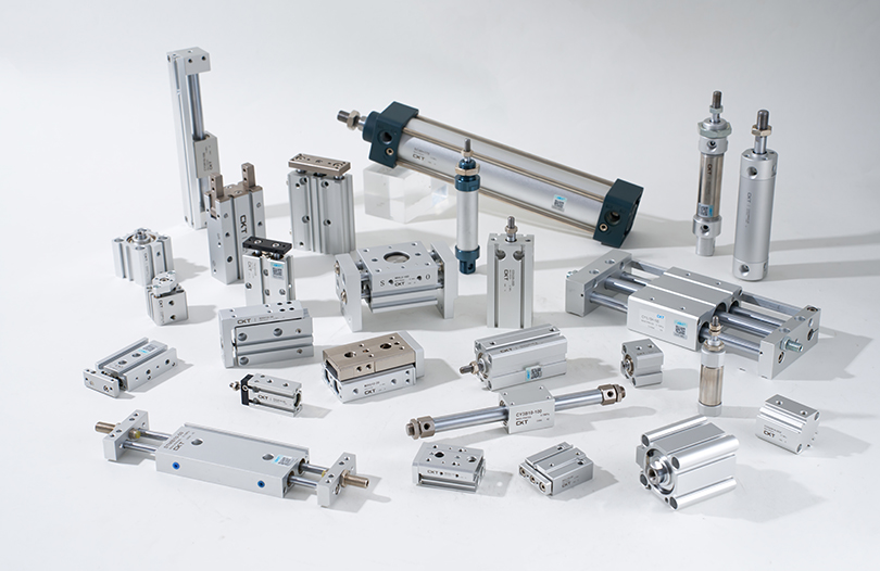
To truly understand Process Valves, we first need to move beyond the one-dimensional understanding of "switches" and interpret them from three dimensions: working principle, core functions, and industrial value. From a professional definition, Process Valves are fluid control devices designed specifically for industrial process control. Compared with household valves (such as tap valves), they can not only realize the basic on-off function but also accurately regulate key parameters such as fluid flow, pressure, and temperature. They also need to adapt to complex working conditions in industrial scenarios, such as high temperature, high pressure, strong corrosion, and high viscosity. Their core working mechanism is to change the effective cross-sectional area of the fluid channel through the movement of internal movable components (such as valve cores, gates, and balls), thereby actively intervening in the fluid transmission process.
In industrial processes, Process Valves play "multiple roles," and each role directly affects the stability and safety of production:
Precise "Flow Regulator": In the production of fine chemicals, the synthesis of a certain pharmaceutical intermediate requires strict control of the ratio of two raw materials (e.g., the ratio of raw material A to raw material B must be maintained at 1:2.5). At this time, two high-precision Process Valves are needed to control the feed flow of the two raw materials respectively. If the valve regulation accuracy is insufficient, even a flow deviation of only 5% may lead to insufficient reaction and increased impurity production, which not only affects product purity (possibly dropping from 99.5% to below 95%) but also increases the cost of subsequent separation and purification. Another example is in the juice concentration process in the food processing industry; Process Valves are required to control the flow of concentrated juice to ensure that the flow rate of the concentrated juice entering the sterilization equipment is stable. This avoids incomplete sterilization due to excessively fast flow rates or local overheating of the equipment and juice deterioration due to excessively slow flow rates.
Reliable "Safety Guardian": In addition to the common safety valves, there are multiple "safety members" in the Process Valve family. For example, in natural gas transmission pipelines, an "emergency shut-off valve" (a type of Process Valve) continuously monitors pipeline pressure and flow. When a pipeline rupture (sudden pressure drop) or leakage (abnormal flow) is detected, it can automatically close within 0.5 seconds to prevent a large amount of natural gas leakage from causing an explosion. In the reactor system of chemical enterprises, an "overflow valve" is also installed. When the liquid level of materials in the reactor exceeds the safe height, the overflow valve will automatically open to discharge excess materials into a backup storage tank, avoiding fire or corrosion accidents caused by material overflow.
Flexible "Process Switcher": Modern industrial production often requires "multi-product, multi-batch" flexible production, and Process Valves are the core components for realizing process switching. Taking an automobile painting workshop as an example, different colors of paint need to be transported to the spray gun through the same set of pipelines. At this time, through the coordinated switching of a group of Process Valves, the process of "conducting the red paint pipeline → cleaning the pipeline after spraying → switching to conducting the blue paint pipeline" can be realized. There is no need to lay separate pipelines for each color, which greatly reduces equipment costs and workshop space occupation. In the distillation tower system of petrochemicals, different fractions such as gasoline, diesel, and kerosene distilled out can be respectively introduced into corresponding storage tanks by switching different Process Valves, realizing continuous and automated production.
II. What Are the Common Types of Process Valves? What Are the Differences in Their Applicable Scenarios?
The classification of Process Valve types is not "arbitrary" but is designed based on different requirements for fluid control in industrial scenarios (such as switching speed, regulation accuracy, sealing requirements, and adaptability to working conditions). Common types include not only gate valves, ball valves, globe valves, and safety valves but also butterfly valves, check valves, diaphragm valves, etc. Each type has its unique structural design and "exclusive" application scenarios. Blindly mixing and matching them can easily lead to equipment failures.
1. Gate Valves: Why Are They Often Used in "Fully Closed" or "Fully Open" Scenarios?
The structural design of gate valves determines their "strengths" and "weaknesses." Their core components include a gate (usually rectangular or wedge-shaped), a valve stem, and a valve seat. During operation, the rotation of the valve stem drives the gate to lift vertically. When the gate is fully lifted, fluid can flow unobstructed along a straight channel, with an extremely low flow resistance coefficient (usually less than 0.1), much lower than that of other types of valves. When the gate is fully lowered, it fits closely with the valve seat to achieve sealing.
In terms of applicable scenarios, the "advantageous fields" of gate valves are concentrated in large-diameter pipelines that need to maintain on-off status for a long time and have no requirements for flow regulation:
Main Water Transmission Pipelines in Waterworks: The diameter of the main pipeline for water supply from urban waterworks to the urban area is usually more than 1 meter, and it needs to supply water 24 hours a day. The low flow resistance characteristic of gate valves can reduce the energy consumption of water pumps (if the flow resistance is too large, the water pump needs to do additional work to maintain water pressure). At the same time, in the long-term fully open state, there is no relative friction between the gate and the valve seat, and the service life can reach more than 10 years.
Steam Headers in Large Power Plants: In thermal power plants, high-temperature and high-pressure steam (temperature up to 540°C, pressure up to 16MPa) generated by boilers is distributed to various turbines through steam headers. The diameter of steam headers is usually 0.8-1.5 meters and needs to remain fully open for a long time. The high-temperature and high-pressure resistance (valve body material is mostly chromium-molybdenum alloy steel) and low flow resistance advantages of gate valves are perfectly adapted to this scenario.
However, the "weaknesses" of gate valves are also very obvious: first, when regulating the flow, if the gate is in a half-open state, the fluid will cause strong "throttling erosion" on the gate sealing surface (the flow rate can be 3-5 times that in the fully open state), which will cause wear on the sealing surface in a short period and lead to leakage. Second, if particulate impurities (such as welding slag left during pipeline welding and sediment in the fluid) enter between the gate and the valve seat, the gate cannot be completely closed, affecting the sealing effect. Therefore, gate valves must not be used in scenarios that require frequent flow regulation (such as reactor feeding in the chemical industry) or scenarios where the fluid has a high solid content (such as tailings transportation in mines).
2. Ball Valves: Why Are They the First Choice in Fast Switching Scenarios?
The structural design of ball valves focuses on "speed and sealing." Their valve core is a ball with a hole in the center (the hole diameter is the same as or slightly smaller than the inner diameter of the pipeline). Sealing seats (mostly made of polytetrafluoroethylene or metal) are installed on both sides of the ball. During operation, the valve stem drives the ball to rotate. When the ball hole is aligned with the pipeline axis, the valve is fully open; after rotating 90°, the ball completely blocks the pipeline, and the valve is fully closed.
This structure endows ball valves with three core advantages, making them the "first choice" in fast switching scenarios:
Extremely Fast Switching Speed: Traditional gate valves require rotating the valve stem multiple times to open or close (e.g., a gate valve with a diameter of 100mm needs to be rotated 10-15 times), while ball valves only need to rotate 90° (about 1-2 seconds for manual operation and can be shortened to within 0.5 seconds for electric operation), which can effectively reduce accident risks in emergency scenarios. For example, in the outlet pipeline of an oil storage tank, if abnormal liquid level drop (possible leakage) of the storage tank is detected, the electric ball valve can close instantly to avoid a large amount of crude oil leakage. In LNG (liquefied natural gas) transmission pipelines, the fast switching characteristic of ball valves ensures that when the system pressure fluctuates, the fluid can be cut off in a timely manner to prevent low-temperature fluid leakage from freezing equipment or personnel.
Excellent Sealing Performance: There is a line contact seal between the ball and the sealing seat (surface contact for some high-pressure ball valves), and the sealing seat material has good elasticity and wear resistance, which can effectively adapt to changes in fluid pressure. Even under low-pressure working conditions (e.g., 0.1MPa), "zero leakage" can be achieved. Therefore, ball valves are widely used in scenarios with high sealing requirements, such as solvent transmission pipelines in the chemical industry (solvents are mostly flammable, explosive, or toxic substances, and leakage can cause safety accidents) and liquid medicine transmission pipelines in the pharmaceutical industry (liquid medicines require high purity, and external impurities are not allowed to enter or liquid medicines to leak).
Strong Contamination Resistance: The surface of the ball is smooth and has a "self-cleaning" effect during rotation. Fine particulate impurities in the fluid are not easy to adhere to the surface of the ball. Therefore, in scenarios where the fluid contains a small amount of impurities (such as urban gas transmission, which may contain trace dust), the failure rate of ball valves is much lower than that of gate valves.
However, ball valves also have their limitations: ordinary ball valves (such as floating ball valves) have low regulation accuracy. If used in scenarios that require precise flow control (such as laboratory reaction devices), large flow fluctuations will occur. Although adjustable ball valves (such as V-port ball valves) can realize flow regulation, they have high costs and are not suitable for high-viscosity fluids (such as asphalt and syrup), because high-viscosity fluids will adhere to the surface of the ball, affecting the switching flexibility of the valve.
3. Globe Valves: What Advantages Do They Have in Flow Regulation Scenarios?
The structural design of globe valves focuses on "precise regulation." Their valve core is disc-shaped (or needle-shaped), and the valve seat is annular. During operation, the valve stem drives the valve core to move up and down along the axis of the valve seat, changing the gap between the valve core and the valve seat to regulate the fluid flow. Compared with ball valves and gate valves, the flow channel of globe valves is "Z"-shaped, and the flow resistance is relatively large when fully open. However, this "disadvantage" becomes an "advantage" for precise regulation—when the fluid flows in the "Z"-shaped flow channel, the flow rate changes more stably, which is convenient for controlling the flow through the slight movement of the valve core.
The precise regulation advantage of globe valves is fully reflected in the following scenarios:
Feed Control of Chemical Reactors: In the synthesis of a certain polymer material, an initiator (such as peroxide) needs to be slowly added to the reactor. The amount of initiator added must be strictly controlled between 0.1% and 0.5% of the total material, and the addition rate must be uniform (excessively fast addition will cause violent reactions and sudden temperature rise; excessively slow addition will prolong the reaction time). At this time, through the slight lifting of the globe valve core (e.g., a lifting range of 0.1mm), the flow rate of the initiator can be controlled within the range of 0.5-1L/h to ensure stable reaction.
Precision Fluid Systems in Laboratories: In environmental monitoring laboratories, it is necessary to accurately transport trace reagents (such as standard solutions with a concentration of 0.01mol/L) to detection instruments through fluid systems. At this time, the regulation accuracy of globe valves can reach ±0.01L/h, much higher than that of ball valves (±0.1L/h), which can effectively ensure the accuracy of detection data.
Temperature Regulation in Heating Systems: In the central heating system of large office buildings, a small globe valve is installed at the water inlet of the radiator in each room. By adjusting the opening degree of the globe valve (e.g., opening 1/4 or 1/2), the flow rate of hot water entering the radiator can be controlled, thereby adjusting the room temperature (from 18°C to 25°C) to meet the temperature needs of different areas.
However, the "high flow resistance" disadvantage of globe valves also limits their application range: in large-flow pipelines (such as cooling water pipelines with a diameter of more than 200mm), if globe valves are used, the pipeline pressure loss will be too large (possibly reaching more than 0.5MPa). Additional water pump power is required to maintain the flow rate, resulting in energy waste. At the same time, there is surface contact between the valve core and the valve seat of globe valves, which is prone to wear after long-term use. The sealing parts (such as valve core seals) need to be replaced regularly, resulting in relatively high maintenance costs.
4. Safety Valves: The "Safety Barrier" of Industrial Systems—What Is Their Working Principle?
Safety valves are the "specialized safety" type among Process Valves. Their design purpose is to prevent industrial systems from exploding, rupturing, and other accidents due to pressure exceeding the allowable range. Therefore, their working principle has two characteristics: "automaticity" and "reliability." The core components of safety valves include a valve core, a valve seat, a spring (or weight), and an adjusting nut. The basic working process is as follows: under normal working conditions, the pressure of the spring (or weight) presses the valve core tightly on the valve seat, and the valve is closed. When the system pressure exceeds the preset value (i.e., the "set pressure" of the safety valve), the fluid pressure overcomes the pressure of the spring (or weight) to lift the valve core, and the valve opens to discharge excess fluid through the discharge port. When the system pressure drops to the "reseating pressure" (usually 5%-10% lower than the set pressure), the pressure of the spring (or weight) presses the valve core back to the valve seat again, the valve closes, and the system returns to normal operation.
According to different driving methods, safety valves can be divided into spring-type, weight-type, pilot-type, etc., and different types have different applicable scenarios:
Spring-Type Safety Valves: They have a simple structure, small size, and are easy to install. They are suitable for most industrial scenarios (such as boilers, pressure vessels, and pressure pipelines). For example, in steam boilers, the set pressure of spring-type safety valves is usually set to 1.05-1.1 times the rated pressure of the boiler (e.g., for a boiler with a rated pressure of 10MPa, the set pressure is set to 10.5MPa). When the steam pressure in the boiler exceeds 10.5MPa, the safety valve automatically opens to release pressure, preventing the boiler from exploding due to overpressure.
Weight-Type Safety Valves: They realize sealing through the gravity of the weight, have high pressure regulation accuracy, but are large in size and have strict requirements on installation angle (must be installed vertically). They are mainly used for fixed equipment (such as large storage tanks and reactors). For example, on the top of an oil storage tank, a weight-type safety valve is installed. When the pressure in the storage tank increases due to material volatilization and exceeds the set pressure, the safety valve opens to discharge the volatile gas to the atmosphere (or a recovery system), preventing the storage tank from deforming.
Pilot-Type Safety Valves: They consist of a main valve and a pilot valve. The pilot valve is responsible for monitoring the system pressure, and the main valve is responsible for pressure relief. They have the characteristics of sensitive action and good sealing performance and are suitable for high-pressure and large-flow scenarios (such as large natural gas pipelines and main steam pipelines of thermal power plants). For example, in long-distance natural gas pipelines, the set pressure of the pilot-type safety valve is set to 1.08 times the design pressure of the pipeline. When the pipeline pressure rises abnormally, the pilot valve opens first, and the main valve is pushed to open through the control oil circuit (or gas circuit) to achieve rapid pressure relief.
It should be noted that the "set pressure" of safety valves must be professionally calibrated and regularly verified (at least once a year). If the set pressure is too high, it will lose its safety protection function; if the set pressure is too low, it will cause the safety valve to open frequently, resulting in fluid waste and equipment wear.
III. How to Properly Maintain Process Valves? Which Maintenance Details Can Extend Their Service Life?
The service life of Process Valves depends not only on product quality but also on the "refinement" of daily maintenance. According to industrial equipment maintenance data statistics, the service life of Process Valves with good daily maintenance can be extended by 30%-50%, and the failure rate can be reduced by more than 60%. However, many enterprises have the misunderstanding of "valuing maintenance over prevention" in the maintenance process. They only carry out maintenance when the valve has problems such as leakage or jamming, which not only increases maintenance costs but also disrupts production schedules. Below, we detail the key maintenance points for Process Valves from three core dimensions: cleaning, lubrication, and leak detection.
1. Regular Cleaning: Why Must Impurities Be Prevented from "Damaging" Valves?
Industrial fluids often contain various impurities, such as sediment in oil, suspended solids in wastewater, scale in steam, and solid particles in chemical raw materials. If these impurities accumulate inside the valve for a long time, they will cause "progressive damage" to valve components:
Wearing Sealing Surfaces: Impurity particles can embed into the sealing surfaces of the valve core and seat, causing scratches and pits that damage the sealing performance and lead to leakage. For example, in the sludge transport pipeline of a wastewater treatment plant, sand particles in the sludge flow with the fluid and continuously erode the gate sealing surface of the gate valve. Without timely cleaning, the gate valve's seal will fail within 3-6 months, resulting in leakage.
Jamming Moving Components: Impurities accumulate in the moving gaps of the valve stem and core, making it difficult for the valve stem to lift or the core to rotate. In severe cases, the valve may become stuck and unable to open or close normally. For instance, in the slurry transport pipeline of the chemical industry, solid particles in the slurry adhere to the gap between the valve stem and body of a ball valve. Without regular cleaning, the valve stem cannot drive the ball to rotate, rendering the valve inoperable.
Clogging Flow Channels: For small-diameter valves (e.g., globe valves with a diameter of less than 15mm), impurity particles in the fluid may block the gap between the valve core and seat, preventing the valve from regulating flow normally. In laboratory reagent transport pipelines, for example, tiny impurities in reagents can block the core gap of globe valves, causing a sudden drop in reagent flow and disrupting experiments.
Differentiated cleaning methods are required for different scenarios:
Scenarios with High Impurity Content (e.g., mine tailings transport, wastewater treatment): Install a "Y-type filter" or "basket filter" before the valve inlet. The filter screen aperture should be selected based on the size of impurity particles (usually 0.1-1mm). Clean the filter once a week (open the filter drain to discharge impurities) and disassemble the filter to clean the screen once a month (rinse with high-pressure water or soak in chemical cleaning agents). Additionally, disassemble the valve every 3 months to thoroughly clean components such as the core, seat, and stem: for metal components, use a wire brush (or sandpaper) to remove surface impurities and rust, then clean with a neutral detergent (e.g., diluted dish soap); for non-metallic components (e.g., PTFE seals), wipe with a soft cloth to avoid scratching the surface with hard tools.
Scenarios with Clean Fluids (e.g., steam, pure water, natural gas): Frequent valve disassembly is unnecessary, but the external surface of the valve should be cleaned every 6 months (blow off dust with compressed air and wipe the valve body with a damp cloth). Regularly check if the valve's exhaust port (e.g., the exhaust port of a safety valve) is blocked; if so, unclog it with a thin wire (or a dedicated cleaning pin).
2. Lubrication Maintenance: Which Components Require Regular Lubrication?
Moving components of Process Valves (e.g., valve stems, bearings, gear transmission mechanisms) generate friction during operation. Without lubrication, component wear accelerates, operation resistance increases, and "seizure" may even occur. Therefore, the core of lubrication maintenance is "selecting the right lubricant, identifying the right lubrication points, and controlling the lubrication cycle."
(1) Identifying Components Requiring Lubrication
Valve Stem: The valve stem is a key component connecting the core and operating mechanism. Its surface usually has threads (for connecting to the core) or a smooth surface (for matching with the stuffing box). During valve operation, the stem rubs against the packing in the stuffing box. Without lubrication, packing wear accelerates, leading to external leakage. Additionally, if the stem threads rust due to friction, lifting the stem becomes difficult, affecting valve operation.
Bearings: Large-diameter valves (e.g., gate valves and ball valves with a diameter of over 300mm) are equipped with bearings (mostly rolling or sliding bearings) between the stem and body to reduce rotational resistance. During operation, friction occurs between the inner/outer rings of the bearing and the rolling elements (or sliding surfaces). Insufficient lubrication causes overheating and wear of the bearing, and in severe cases, "bearing seizure," which disables the valve.
Gear Transmission Mechanisms: Electric or pneumatic valve actuators typically include gear transmission mechanisms (e.g., spur gears, bevel gears) to transmit power from the motor or cylinder to the valve stem. Without lubrication at the gear meshing points, tooth surface wear accelerates, leading to "tooth gluing" (metal surface adhesion at high temperatures) or "tooth spalling," which impairs power transmission efficiency and may cause actuator failure.
(2) How to Select the Right Lubricant?
Lubricant selection must align with the valve's operating conditions (temperature, pressure, fluid properties) and component materials. Significant differences exist between lubricant types for different scenarios:
High-Temperature Conditions (temperature > 200°C, e.g., steam pipelines, high-temperature hot oil pipelines): High-temperature-resistant lubricants such as molybdenum disulfide grease (resistant to temperatures up to 350°C) and calcium sulfonate complex grease (resistant to temperatures up to 250°C) are required. These lubricants do not decompose or run off at high temperatures and form a stable lubricating film on component surfaces. For example, the stem and bearings of gate valves in steam headers should be coated with molybdenum disulfide grease to prevent lubricant failure at high temperatures.
Low-Temperature Conditions (temperature < -20°C, e.g., LNG pipelines, low-temperature ethylene glycol pipelines): Low-freezing-point lubricants such as PTFE-based grease (freezing point < -60°C) and silicone-based grease (freezing point < -40°C) are necessary. Ordinary lubricants solidify and lose lubricity at low temperatures, while these lubricants maintain good fluidity. For instance, the stem and sealing seat of ball valves in LNG transport pipelines should be coated with PTFE-based grease to ensure normal valve operation at low temperatures.
Corrosive Conditions (fluids are acids, alkalis, or salt solutions, e.g., acid-base transport pipelines in the chemical industry): Corrosion-resistant lubricants such as fluorocarbon grease (resistant to strong acids and alkalis) and PEEK (polyetheretherketone)-based grease (resistant to chemical corrosion) are required. These lubricants resist fluid erosion, prevent chemical reactions between the lubricant and fluid, and protect component surfaces from corrosion. For example, the stem of globe valves in hydrochloric acid transport pipelines should be coated with fluorocarbon grease to prevent corrosion of the stem by hydrochloric acid vapor and damage to the lubricating film.
Normal Conditions (temperature -20°C to 200°C, fluids are water, air, or ordinary oil products, e.g., tap water pipelines, hydraulic oil pipelines): General-purpose lubricants such as lithium-based grease (suitable for temperatures -20°C to 120°C) and calcium-based grease (suitable for temperatures -10°C to 60°C) can be used. These lubricants are cost-effective and meet the lubrication needs of most normal working conditions.
(3) Lubrication Cycles and Operating Methods
The lubrication cycle is determined by the valve's usage frequency and the severity of operating conditions. The principle of "shorter cycles for high-frequency use and harsh conditions" generally applies:
High-Frequency Use Valves (e.g., ball valves and globe valves switched more than 5 times per hour): Lubricate the stem and bearings once a month, and the gear transmission mechanism once every 2 months.
Medium-Frequency Use Valves (e.g., gate valves and check valves switched about 10 times per day): Lubricate the stem and bearings once every 3 months, and the gear transmission mechanism once every 6 months.
Low-Frequency Use Valves (e.g., safety valves and overflow valves switched 1-2 times per month): Lubricate the stem and bearings once every 6 months, and the gear transmission mechanism once a year.
Valves in Harsh Conditions (high temperature, low temperature, corrosive environments): Shorten the lubrication cycle by 50%. For example, valves in high-temperature conditions require stem lubrication every 1.5 months instead of 3 months.
Lubrication operations follow the "cleaning-coating-inspection" process:
Cleaning: Before lubrication, wipe dust and impurities from component surfaces with a cloth. If old lubricant residue (hardened or deteriorated) remains on the surface, clean it with a solvent (e.g., gasoline, alcohol) to prevent mixing of old and new lubricants, which impairs lubrication effectiveness.
Coating: Apply lubricant evenly to component surfaces. The amount of lubricant should be moderate—apply a 0.5-1mm thick layer to stem threads (just enough to cover the threads), fill 1/3-1/2 of the bearing internal space (excessive lubricant causes bearing overheating), and apply a 0.2-0.3mm thick layer to gear meshing points (to ensure uniform coverage of tooth surfaces).
Inspection: After lubrication, manually or electrically operate the valve 1-2 times to check if operation is smooth. If increased resistance or abnormal noise is detected, check if the lubricant is evenly applied or if components are jammed.
3. Leak Detection: How to Timely Identify Valve Leakage?
Valve leakage is the most common type of failure. Failure to detect leaks in a timely manner leads to fluid waste, environmental pollution, and even safety accidents (e.g., explosions caused by leakage of flammable and explosive fluids). Therefore, leak detection requires a combination of "regular detection" and "daily inspection," using multiple methods to ensure no leakage risks.
(1) External Leakage Detection: Visually Inspecting External Leaks
External leakage refers to fluid leaking from the valve's stuffing box, flange connections, or body defects to the outside. It can usually be detected using three methods: visual inspection, soapy water testing, and leak detector testing.
Visual Inspection: During daily inspections, observe if there are fluid traces (e.g., water droplets, oil stains, crystals) on the external surface of the valve. For example, if a gate valve in a tap water pipeline leaks from the stuffing box, water droplets form around the valve stem. If a ball valve in a chemical pipeline leaks from the flange connection, crystals form around the flange sealing surface (some chemical fluids crystallize when exposed to air). Note that visual inspection is ineffective for detecting leaks in gas valves (e.g., natural gas ball valves), so other methods are required.
Soapy Water Testing: For gas valves or liquid valves with suspected leaks, apply soapy water (or diluted dish soap) to potential leak points (stuffing box, flange sealing surface, valve body welds). If bubbles form, a leak exists, and the frequency of bubble formation indicates the leak rate. For example, when testing the flange connection of a natural gas pipeline ball valve, if 5-10 bubbles form per second after applying soapy water, the leak rate is high, and emergency maintenance is required.
Leak Detector Testing: For scenarios requiring high precision (e.g., liquid medicine valves in the pharmaceutical industry, gas valves in the semiconductor industry), professional leak detectors (e.g., ultrasonic leak detectors, hydrogen leak detectors) are used. Ultrasonic leak detectors detect ultrasonic signals generated by valve leaks (fluid leakage produces high-frequency vibrations) and can identify micro-leaks (leak rate < 0.1mL/min). Hydrogen leak detectors detect hydrogen leakage (a small amount of hydrogen is injected into the valve; detection of hydrogen outside indicates a leak) and are suitable for scenarios with strict leak rate requirements.
(2) Internal Leakage Detection: Inspecting Leaks Between the Valve Core and Seat
Internal leakage refers to fluid leaking between the valve core and seat (fluid continues to flow downstream after the valve is closed). Since internal leakage occurs inside the valve, it is difficult to observe directly and requires judgment using flow detection, pressure detection, and temperature detection methods.
Flow Detection: After closing the valve, install a flowmeter (e.g., turbine flowmeter, electromagnetic flowmeter) in the downstream pipeline. If the flowmeter shows flow (the allowable internal leak rate is usually < 0.1% of the rated flow), an internal leak exists. For example, after closing the feed globe valve of a chemical reactor, if the downstream flowmeter shows a flow rate of 0.5L/h (rated flow is 100L/h), the internal leak rate reaches 0.5%, exceeding the allowable range, and the valve core and seat require maintenance.
Pressure Detection: After closing the valve, install a pressure gauge in the downstream pipeline and record the initial pressure. If the pressure continues to rise (indicating upstream fluid leaking into the downstream through internal leaks) or fails to maintain after closing the downstream exhaust valve (indicating downstream fluid leaking back to the upstream through internal leaks), an internal leak exists. For example, after closing a gate valve in a steam pipeline, the initial pressure in the downstream pipeline is 0MPa, and rises to 0.2MPa after 1 hour, indicating an internal leak, and the gate sealing surface requires inspection.
Temperature Detection: For valves handling high-temperature or low-temperature fluids, temperature detection can be used to determine internal leaks. For example, after closing a globe valve in a steam pipeline, the temperature of the downstream pipeline should gradually decrease. If the temperature remains unchanged or decreases slowly, high-temperature steam is leaking into the downstream through internal leaks. After closing a ball valve in an LNG pipeline, the temperature of the downstream pipeline should gradually rise. If the temperature remains low (e.g., below -160°C), low-temperature LNG is leaking into the downstream through internal leaks.
(3) Leakage Treatment: How to Respond After Detecting a Leak?
Once a leak is detected, appropriate treatment measures are taken based on the leak type and rate:
Minor External Leaks (e.g., slight seepage from the stuffing box without obvious dripping): First, try tightening the stuffing box gland bolts (tighten evenly to avoid stem deformation due to uneven force on one side). If the leak stops after tightening, the valve can continue to be used; if the leak persists, shut down the valve to replace the packing (select packing type suitable for operating conditions).
Severe External Leaks (e.g., significant dripping from flange connections, cracked valve body causing leakage): Immediately shut down the valve, close the isolation valves upstream and downstream of the faulty valve, drain fluid from the pipeline, and then perform maintenance—replace the sealing gasket for flange leaks (check if the flange sealing surface has scratches; if so, grind and repair it); replace the valve for cracked valve bodies (check if the valve body material is suitable for operating conditions to avoid repeated cracking).
Minor Internal Leaks (internal leak rate < 0.1% of rated flow without affecting production): The valve can continue to be used temporarily, but the inspection frequency should be shortened (e.g., from once a day to once every 4 hours) to monitor if the leak rate increases. If the leak rate gradually increases, shut down the valve for maintenance (e.g., grind the valve core and seat sealing surfaces, or replace the core and seat).
Severe Internal Leaks (internal leak rate > 0.5% of rated flow or affecting production safety): Immediately shut down the valve, disassemble it to inspect the wear of the core and seat. If the sealing surface wear is slight, repair it by grinding (use abrasive paste and follow the steps of rough grinding, fine grinding, and precision grinding). If the sealing surface wear is severe (scratch depth > 0.2mm), replace the core or seat.
IV. What Mistakes Are Easily Made When Selecting Process Valves? How to Avoid Them?
During the selection of Process Valves, many enterprises or practitioners fall into selection mistakes due to incomplete knowledge of valves, overemphasis on a single indicator (e.g., price, diameter), or blind replication of selection experience from other scenarios. These mistakes result in valves that cannot meet operating requirements, increasing equipment replacement costs and potentially causing production accidents. Below are three common mistakes and corresponding avoidance methods to help practitioners select valves accurately.
1. Mistake 1: Focusing Only on Price and Ignoring the Matching of Valve Material to Operating Conditions
Some purchasers prioritize price when selecting valves, choosing low-cost options while ignoring the compatibility of valve materials with operating conditions (fluid properties, temperature, pressure). This "price-driven selection" approach seems to reduce procurement costs but actually leads to rapid valve damage due to material mismatch, increasing subsequent maintenance and replacement costs and even causing safety accidents.
Typical Case
A chemical enterprise selected ordinary carbon steel ball valves (unit price approximately 800 yuan) for a pipeline transporting 30% hydrochloric acid (temperature 25°C, pressure 0.8MPa) to reduce costs. Carbon steel cannot resist hydrochloric acid corrosion, so the valve body developed severe corrosion holes within 1 month, leading to hydrochloric acid leakage. This caused corrosion of workshop floors and equipment damage. Later, the enterprise had to replace the valves with corrosion-resistant 316L stainless steel ball valves (unit price approximately 3,000 yuan) and compensate for equipment damage, resulting in total costs far exceeding the initial procurement savings.
Avoidance Method
Prioritize "material suitability" when selecting valves, and accurately select valve body, core, and seal materials based on operating parameters:
Clarify Operating Parameters: Record detailed information about the fluid type (corrosive, flammable, explosive, toxic), concentration (e.g., 30% hydrochloricacid, 98% sulfuric acid), temperature range (e.g., -10°C to 80°C), and operating pressure (e.g., 0.5MPa to 2.5MPa). These parameters are the core basis for material selection.
Match Material Properties: Select valve body materials based on fluid characteristics—for corrosive fluids (acids, alkalis, salt solutions), prioritize stainless steel (304, 316L), Hastelloy, or titanium alloy; for high-temperature fluids (>300°C), choose chrome-molybdenum alloy steel (15CrMo, 25CrMo); for low-temperature fluids (<-40°C), select low-temperature steel (09MnNiD, 16MnD); for ordinary fluids (water, air, mineral oil), carbon steel (Q235, 20# steel) is acceptable.
Verify Material Certifications: Request material certification documents (e.g., material test reports, third-party inspection certificates) from valve suppliers to ensure the actual valve material matches the stated specifications. Avoid suppliers cutting corners (e.g., using 201 stainless steel instead of 304 stainless steel).
2. Mistake 2: Blindly Pursuing Large Diameters and Ignoring Actual Flow Requirements
Some practitioners believe that "larger diameters mean more sufficient flow" and blindly select valves larger than the pipeline diameter or choose large-diameter valves without calculating actual flow. This not only increases procurement costs (large-diameter valves are far more expensive than small-diameter ones) but also reduces valve regulation accuracy and accelerates fluid erosion, shortening the valve's service life.
Typical Case
A food factory selected an 80mm-diameter globe valve for a juice transport pipeline (pipeline diameter 50mm, actual flow 10m³/h) to "ensure sufficient flow." During use, the globe valve had to remain in a "small opening" state (only 10%-20% open) to control flow. At this point, the juice flow rate reached 5m/s (normal flow rate should be 1-2m/s). The high-velocity fluid caused severe erosion to the valve core sealing surface, leading to serious internal leakage within 3 months. The valve could no longer control flow accurately and had to be replaced with a 50mm-diameter globe valve.
Avoidance Method
When selecting valves, calculate the appropriate valve diameter based on actual flow requirements and the valve's flow characteristic curve to avoid "using a large valve for small flow":
Calculate Actual Flow: Determine the maximum, normal, and minimum flow rates of the pipeline based on production process requirements. The normal flow rate is usually used as the basis for diameter calculation. For example, for the feed pipeline of a chemical reactor, the maximum flow rate is 15m³/h, normal flow rate is 10m³/h, and minimum flow rate is 5m³/h. The 10m³/h normal flow rate should be used for diameter calculation.
Reference Flow Characteristic Curves: Valve suppliers typically provide flow characteristic curves for different diameter valves (showing the relationship between valve opening and flow rate). When selecting a diameter, ensure the valve opening corresponding to the normal flow rate is between 30% and 70%—opening below 30% may cause sealing surface wear due to excessive flow velocity; opening above 70% leaves insufficient adjustment margin to cope with flow fluctuations.
Match Pipeline Diameter: Unless there are special requirements (e.g., need for additional flow reserves), the valve diameter should match the pipeline diameter or be one size smaller (e.g., for a 50mm-diameter pipeline, a 40mm or 50mm valve can be selected) to avoid adjustment issues caused by oversized diameters.
3. Mistake 3: Ignoring Sealing Performance and Focusing Only on On-Off and Regulation Functions
Some practitioners only focus on whether the valve can achieve on-off or flow regulation during selection, while ignoring the importance of sealing performance. Especially in scenarios involving flammable, explosive, toxic, or high-value fluids, insufficient sealing performance can lead to serious consequences.
Typical Case
A pharmaceutical factory selected a ball valve with ordinary sealing performance (leakage class ANSI Class IV, allowing minor internal leakage) for a pipeline transporting highly toxic liquid medicine (used in cancer drug production, expensive and toxic). During use, internal leakage of the ball valve caused a small amount of liquid medicine to leak into the downstream pipeline, resulting in not only monthly losses of approximately 50,000 yuan due to liquid medicine waste but also workshop environmental pollution from volatile liquid medicine. Employees even developed mild poisoning symptoms. The issue was only resolved after replacing the valve with an ANSI Class VI (zero-leakage) ball valve.
Avoidance Method
During selection, clarify the valve's sealing requirements based on the fluid's hazard level and value, and ensure sealing performance from three dimensions: sealing class, sealing structure, and sealing material:
Determine Sealing Class: Select the sealing class based on industry standards. Common sealing class standards include ANSI (American National Standards Institute) and ISO (International Organization for Standardization). ANSI Class VI is the highest sealing class (zero leakage) and is suitable for flammable, explosive, toxic, or high-value fluids; ANSI Class IV is suitable for ordinary fluids (water, air).
Select Appropriate Sealing Structures: Choose the sealing structure based on sealing requirements—soft seals (sealing materials: rubber, PTFE) offer good sealing performance (up to ANSI Class VI) but poor high-temperature and high-pressure resistance (suitable for temperatures <200°C, pressures <2.5MPa); hard seals (sealing materials: metal, e.g., stainless steel, cemented carbide) have good high-temperature and high-pressure resistance (suitable for temperatures >300°C, pressures >10MPa) but slightly lower sealing performance (usually ANSI Class IV, which can be improved to ANSI Class V through grinding).
Verify Sealing Performance: Request the supplier to provide valve sealing performance test reports (e.g., bubble test reports, pressure decay test reports). If necessary, conduct on-site sealing tests (e.g., soapy water test, leak detector test) to ensure the valve's sealing performance meets requirements.
V. What Are the Key Precautions for Process Valve Installation? What Problems Can Incorrect Installation Cause?
The installation quality of Process Valves directly affects their subsequent operational stability. Many valve failures stem not from the product itself but from non-standard installation operations. Incorrect installation can cause valve jamming, seal leakage, shortened service life, and even safety accidents. Therefore, it is essential to focus on key details during installation.
1. Pre-Installation Preparation: Essential Inspection Steps
Pre-installation preparation must cover three dimensions—"valve itself, pipeline environment, and tools/materials." Omissions in any link can 埋下 hidden dangers:
Valve Appearance and Component Integrity Inspection (with Testing Tips):
Beyond routine checks for cracks and deformation, use specialized tools for auxiliary testing—use an ultrasonic thickness gauge to check the valve body wall thickness (wall thickness deviation should be ≤5% of the design value; e.g., for a design wall thickness of 10mm, the actual thickness should be ≥9.5mm) to avoid reduced pressure-bearing capacity due to uneven wall thickness; use a feeler gauge to check the fit gap between the valve core and seat (gap ≤0.05mm for ordinary valves, ≤0.02mm for precision valves) to ensure sealing performance; for electric valves, conduct a power-on test of the actuator's opening/closing stroke (stroke deviation should be ≤±1%; e.g., for a rated stroke of 50mm, the actual stroke should be 49.5-50.5mm) to prevent inaccurate stroke from causing incomplete valve opening/closing. If the valve nameplate information (model, pressure class, material) does not match the design drawings, return the valve to the supplier even if its appearance is intact to avoid incorrect valve use.
Pipeline Pre-Treatment Inspection (Scenario-Specific Operations):
Pipeline pre-treatment requirements vary by fluid type:
For pipelines transporting clean fluids (e.g., pure water, pharmaceutical liquid medicine), flush the pipeline with high-pressure pure water (0.8-1.2MPa) for 1-2 hours, then dry it with compressed air (0.5MPa) to ensure no residual impurities (judge by placing white filter paper at the pipeline outlet to check for stains);
For pipelines transporting high-temperature fluids (e.g., steam, high-temperature hot oil), degrease the pipeline (wipe the inner wall with carbon tetrachloride or ethanol) to prevent grease carbonization at high temperatures, which can adhere to the valve sealing surface and affect sealing;
For pipelines transporting corrosive fluids (e.g., hydrochloric acid, sulfuric acid), check the integrity of the inner wall's anti-corrosion layer (e.g., plastic-lined, rubber-lined layers) and use a spark tester (15-30kV voltage) to detect pinholes in the anti-corrosion layer (if the tester alarms, a pinhole exists and the anti-corrosion layer needs to be repaired).
Meanwhile, the parallelism deviation of pipeline flanges should be ≤0.1mm/m. If the deviation is too large, use a flange aligner to adjust to avoid forced alignment during installation.
Preparation of Installation Tools and Auxiliary Materials (with Selection Standards):
Tool selection must accurately match the valve type:
For flange-connected valves, prepare a torque wrench (accuracy class ≥±3%; e.g., for installing a DN100, PN1.6MPa flange valve, select a torque wrench with a range of 0-300N·m) and check the torque value based on bolt specifications (e.g., for an M20 carbon steel bolt at 25°C, the rated torque is 80-100N·m; for stainless steel bolts, due to good ductility, the torque should be reduced by 10%-15% to 72-85N·m);
For welded valves (e.g., high-pressure gate valves for power plants), prepare a TIG welder (current adjustment range 50-300A). The welding rod must match the valve body material (e.g., use E5015-G welding rods for chrome-molybdenum alloy steel valve bodies. Before welding, dry the rods at 350°C and keep them warm for 1-2 hours to prevent porosity during welding);
For auxiliary materials, gasket materials must strictly match the working conditions: use flexible graphite composite gaskets (pressure resistance ≤4.0MPa) for temperatures >400°C, PTFE gaskets (acid and alkali resistant but temperature ≤200°C) for corrosive fluids, and metal wound gaskets (wound from stainless steel strips and graphite strips, with excellent sealing performance) for high-pressure conditions (>10MPa).
2. Installation Operation Specifications: Details That Determine Installation Quality
The installation process must follow the principles of "accurate alignment, even force application, and stress-free installation." Each operation step has clear technical standards:
Valve Installation Direction: Never Install Reversed (with Methods to Identify Easily Confused Valves):
Beyond valves marked with flow direction arrows, some valves have easily confused installation directions and require special identification:
Check valves: Lift check valves (valve discs lift vertically) must be installed in horizontal pipelines with the disc facing upward; swing check valves (valve discs rotate around a shaft) can be installed in horizontal or vertical pipelines, with flow entering from the direction that opens the disc;
Throttle valves: With conical or needle-shaped cores, they must be installed in the "low-in, high-out" direction (fluid enters from the bottom of the core and exits from the top). Reversed installation reduces regulation accuracy by more than 50%;
Pressure reducing valves: Pilot-operated pressure reducing valves must be installed in the "high-pressure in, low-pressure out" direction, with a pressure gauge installed on the outlet side (range 1.5-2 times the outlet pressure) to prevent outlet overpressure.
After installation, mark the flow direction on the valve body with a marker for easy inspection and maintenance later.
Pipeline and Valve Alignment: Avoid Forced Installation (with Deviation Adjustment Tips):
When the axis deviation between the pipeline and valve exceeds 0.5mm/m, adjust by changing the pipeline support position:
For small deviations (0.5-1mm/m), loosen the fixing bolts of the pipeline support and gently adjust the pipeline position with a crowbar. For every 100mm length adjusted, the deviation should be controlled within 0.1mm;
For large deviations (>1mm/m), replace the pipeline nipple (cut a suitable length of pipeline and re-weld) to ensure alignment accuracy.
During installation, use a laser alignment tool (accuracy ±0.01mm/m) to detect axis deviation and avoid errors caused by visual judgment. Meanwhile, reserve a certain expansion gap for the pipelines at both ends of the valve (e.g., for pipelines with temperatures >100°C, reserve a 10-15mm gap for every 10m length) to prevent pipeline expansion/contraction due to temperature changes from exerting additional stress on the valve.
Bolt Tightening: Even Force Application Is Key (with Step-by-Step Operation Process):
Flange bolt tightening requires three steps to ensure even force application:
Initial tightening: Use a torque wrench to tighten bolts in a diagonal sequence to 30% of the rated torque (e.g., for a rated torque of 100N·m, initial torque is 30N·m). At this point, the gasket begins to fit the sealing surface;
Intermediate tightening: After an interval of 15-20 minutes (to allow the gasket to fully deform), tighten the bolts to 70% of the rated torque (70N·m) in the same sequence. Use a feeler gauge to check the flange gap (gap ≤0.05mm and evenly distributed);
Final tightening: After another 15-20 minutes, tighten the bolts to the rated torque (100N·m). After final tightening, mark the bolt positions (draw an alignment line on the bolt and flange with paint) to facilitate inspection for looseness during subsequent patrols.
For large-diameter flanges (>300mm), increase the number of tightening cycles (4-5 times) to avoid incomplete gasket compression and subsequent leakage.
3. Common Consequences of Incorrect Installation: Problems to Watch Out For (with Accident Case Analysis)
The consequences of incorrect installation are often "delayed" and may only appear 1-3 months after installation. Early warning is essential:
Valve Jamming (with Case and Solution):
A refinery installed a DN200 gate valve with an axis deviation of 1.2mm/m between the pipeline and valve. Forced alignment caused the valve stem to bear bending stress. After 2 months of use, the gate valve experienced jamming during opening/closing and required a cheater bar to operate. Disassembly revealed the valve stem was bent (bending degree 0.5mm/m) and the valve core and seat were unevenly worn. Solution: Replace the bent valve stem, adjust the pipeline alignment accuracy with a flange aligner, and re-install. After re-installation, the gate valve operated smoothly again.
Prevention Tip: After installation, manually operate the valve 3-5 times to check for jamming. If abnormal, immediately inspect the alignment accuracy.
Sealing Surface Leakage (with Leak Cause Investigation Steps):
A chemical plant experienced continuous leakage at the flange connection after installing a DN150 globe valve. Initially, it was minor seepage, but the leak increased after 1 week. Investigation steps: 1. Re-tighten the bolts with a torque wrench and found some bolts only had 50% of the rated torque (due to non-diagonal tightening during installation); 2. Disassemble the flange and found uneven indentations on the gasket (deep on one side, shallow on the other); 3. Inspect the flange sealing surface and found residual welding slag (pipeline not cleaned). Solution: Clean the welding slag from the sealing surface, replace the gasket, and tighten the bolts step-by-step according to the standard torque. The leakage issue was resolved.
Prevention Tip: Conduct a pressure test immediately after installation (test pressure 1.2-1.5 times the working pressure, hold for 30 minutes with no leakage as qualified).
Valve Body Damage (with Material Performance Change Testing):
A power plant installed a high-temperature, high-pressure gate valve (material 12Cr1MoVG) without cooling measures during welding (welding temperature exceeded 800°C and no post-weld heat treatment was performed), causing intergranular corrosion in the valve body's welded area. After 6 months of use, a crack appeared in the welded area of the valve body, and high-pressure steam leaked. Testing revealed the hardness of the welded area dropped from 180HB to 120HB, significantly reducing material toughness. Solution: Replace the damaged valve body, use water cooling during welding (control welding temperature ≤600°C), and perform stress relief treatment at 250°C for 2 hours after welding to avoid intergranular corrosion.
VI. How to Handle Process Valve Failures in Different Working Conditions?
Emergency handling of Process Valve failures must follow the principles of "safety first, rapid isolation, and loss minimization." Handling procedures vary significantly by working condition, requiring scenario-specific plans.
1. Valve Failures in Flammable and Explosive Fluid Pipelines: Prioritize Isolating Hazard Sources (with Detailed Operation Process)
Improper handling of valve failures in flammable and explosive fluid pipelines can cause explosions. Strict adherence to steps is essential:
Leakage Emergency Handling (Classified by Leak Rate):
Minor Leaks (leak rate <5mL/min, no obvious gas volatilization): Immediately close the isolation valves upstream and downstream of the valve (wear anti-static gloves during operation to avoid generating static sparks), turn on the on-site explosion-proof exhaust fan (air volume ≥1000m³/h), and use a leak detector to monitor the leakage concentration (e.g., natural gas leakage concentration must be ≤0.5% LEL, i.e., 5% of the lower explosive limit). If the concentration drops to a safe range, temporarily seal the leak point with a dedicated sealant (e.g., explosion-proof PTFE sealant) and schedule thorough maintenance during production breaks;
Moderate Leaks (leak rate 5-50mL/min, obvious gas volatilization): In addition to closing isolation valves and turning on ventilation, set up a warning zone (radius ≥10m) around the site to prohibit unauthorized personnel entry. Use explosion-proof tools to disassemble the valve (to avoid sparks from tool collisions), replace the sealing components, and reinstall. After installation, conduct an airtightness test (test pressure 1.1 times the working pressure, hold for 1 hour, leakage rate ≤0.1%/h);
Severe Leaks (leak rate >50mL/min, or gas concentration approaching the lower explosive limit): Immediately activate the emergency response plan, evacuate all on-site personnel, shut down the system’s main power supply (to prevent sparks from electrical equipment), turn on the plant’s fire sprinkler system (to lower ambient temperature and prevent explosions), and contact professional emergency teams (e.g., fire departments, explosion-proof maintenance teams) for on-site handling. Do not attempt to disassemble the valve independently.
Valve Jamming Emergency Handling (with Standby Pipeline Switching Tips):
If the valve jams and cannot close, switch to the standby pipeline within 3 minutes:
Quickly open the inlet valve of the standby pipeline (rotate the handwheel 2-3 turns counterclockwise to ensure full opening);
Slowly open the outlet valve of the standby pipeline (monitor the downstream flowmeter to avoid pipeline impact from sudden flow changes);
Close the inlet valve of the faulty pipeline (if the inlet valve is also jammed, close the main isolation valve further upstream);
Open the drain valve of the faulty pipeline (open slowly to discharge residual fluid and prevent accumulation-related hazards).
After switching, verify that the standby pipeline’s pressure and flow are normal to ensure continuous production.
2. Valve Failures in High-Temperature and High-Pressure Fluid Pipelines: Prevent Burns and Equipment Damage (with Protection and Pressure Relief Standards)
Leakage of high-temperature and high-pressure fluids (temperature >200°C, pressure >1.6MPa) can cause burns and pipeline bursts. Emergency handling must prioritize protection and pressure relief:
Valve Leakage Emergency Handling (with Protective Equipment and Temporary Sealing Methods):
Operators must wear full high-temperature protective gear: heat-resistant gloves (temperature resistance ≥500°C, e.g., aramid gloves), heat-resistant face shields (shield glass temperature resistance ≥800°C), and high-temperature protective clothing (e.g., aluminum foil composite fabric, temperature resistance ≥600°C). Follow these steps:
Slowly close the upstream and downstream isolation valves (control the closing speed to 10-15 seconds per turn to avoid water hammer—water hammer pressure can reach 3-5 times the normal pressure and damage pipelines);
If the leak is at the flange connection, use a dedicated flange sealing clamp (composed of a stainless steel frame and graphite gasket, pressure resistance ≤10MPa) for temporary sealing: fit the clamp around the flange, adjust the bolts to press the gasket tightly against the flange surface until the leak stops;
If the valve body cracks and leaks (large leak rate), immediately open the system pressure relief valve (control the pressure relief rate to 0.1-0.2MPa/min to avoid equipment deformation from sudden pressure drops). Once the pressure drops below 0.1MPa, close the main isolation valve and replace the valve body.
During handling, use an infrared thermometer to monitor the valve body temperature (to prevent protective gear failure from excessive heat). If the temperature exceeds 600°C, cool the valve body first (with compressed air) to below 300°C before proceeding.
Safety Valve Failure Emergency Handling (with Manual Pressure Relief and Standby Valve Replacement Process):
Safety valve failure (failure to open or close) is a major hazard in high-pressure systems. Follow this handling process:
Immediately open the manual pressure relief valve (rotate the handwheel clockwise to open slowly, control the pressure relief rate to reduce system pressure by 0.5-1.0MPa per hour), and closely monitor the pressure gauge to prevent pressure from dropping too low and disrupting production;
Close the isolation valves upstream and downstream of the faulty safety valve (if the isolation valve is a gate valve, rotate the handwheel to fully close and lock it to prevent accidental operation);
Disassemble the faulty safety valve (use a dedicated wrench to avoid damaging the flange sealing surface) and install a calibrated standby safety valve (with the same set pressure as the original);
Slowly open the isolation valves upstream and downstream of the standby safety valve, close the manual pressure relief valve, and verify that the system pressure is stable (normal fluctuation range ≤±0.05MPa);
Send the faulty safety valve to a professional institution for calibration (inspect spring stiffness and valve core sealing surface; replace fatigued springs and grind worn sealing surfaces) before reuse.
3. Valve Failures in Corrosive Fluid Pipelines: Prevent Corrosion Spread (with Neutralization and Cleaning Standards)
Leakage of corrosive fluids can cause equipment corrosion and soil pollution. Emergency handling must prioritize protection, collection, and neutralization:
Leakage Emergency Handling (with Protective Equipment and Neutralization Steps):
Operators must wear corrosion-resistant protective gear: acid-resistant gloves (e.g., nitrile rubber gloves, resistant to concentrated hydrochloric acid and sulfuric acid), corrosion-resistant clothing (e.g., PVC clothing, resistant to most acids and alkalis), and chemical splash goggles (polycarbonate lenses). Follow these steps:
Close the upstream and downstream isolation valves (use plastic wrenches to avoid corrosion of metal tools);
Collect the leaked fluid in a corrosion-resistant container (e.g., a polyethylene bucket with a capacity ≥50L). Pre-add a neutralizing agent to the bucket (e.g., add sodium carbonate solution to neutralize leaked hydrochloric acid to pH 6-8; add dilute hydrochloric acid to neutralize leaked sodium hydroxide to pH 6-8) to prevent direct discharge;
Rinse the leaked area with plenty of water (rinse volume ≥10L/m², rinse time ≥5 minutes). Discharge the rinse water into a dedicated corrosion-resistant wastewater treatment tank, not directly into sewers;
Disassemble the faulty valve (rinse the valve surface with water to remove residual corrosion), inspect for corrosion on the valve core and seat (e.g., replace stainless steel cores with Hastelloy cores if pitting occurs), replace damaged components, and reinstall. After installation, conduct an airtightness test (with nitrogen, test pressure 1.2 times the working pressure, hold for 30 minutes with no leakage).
VII. What Should Be Focused on During Daily Inspections of Process Valves? Keep This Inspection Checklist Handy
Daily inspections must be "comprehensive and thorough," combining "visual inspection, tool testing, and operation verification" to identify hazards promptly. Below is a detailed inspection checklist, with frequency and depth adjusted based on valve importance (critical vs. general valves) to optimize resource allocation.
1. Inspection Standards Classified by Valve Importance
In industrial systems, valves are classified by function into critical valves (e.g., reactor feed valves, steam header safety valves, flammable fluid isolation valves) and general valves (e.g., ordinary cooling water gate valves, drain valves). Their inspection requirements differ significantly:
Critical Valves (Inspection Frequency: Once per day, 24-hour monitoring for some):
In addition to basic checks, add "high-precision testing" and "status recording":
Use pressure transmitters to monitor real-time pressure differences across the valve (e.g., for reactor feed globe valves, the normal pressure difference should be ≤0.2MPa; a sudden increase indicates possible valve core blockage) and record hourly pressure data;
For electric valves, use a multimeter to test actuator current and voltage (e.g., for a rated current of 10A, actual current fluctuation should be ≤±0.5A; abnormal current indicates motor failure or valve core jamming);
Conduct an "offline test" once per week: close the upstream and downstream isolation valves, pressure-test the valve (test pressure 1.1 times the working pressure, hold for 1 hour), and inspect sealing performance;
Establish a "valve health record" to document pressure, flow, and operation feel during each inspection. Use trend analysis to assess valve aging (e.g., a monthly increase of 0.1mL/min in sealing surface leakage indicates aging seals requiring proactive replacement).
General Valves (Inspection Frequency: Once per week, in-depth inspection once per month):
Focus on "basic function verification" to reduce unnecessary testing costs:
Visually inspect the valve body for obvious corrosion or leakage and check if the operation handle is intact;
Manually operate the valve once per month (full open-close cycle) to check for jamming. If resistance increases significantly, perform lubrication maintenance;
Inspect flange bolts for looseness once per quarter (use a wrench to gently turn bolts; re-tighten to 80% of the rated torque if bolts turn more than 1/4 turn);
For infrequently used valves (e.g., drain valves), open them once per month (for 5-10 seconds) to prevent valve core jamming from prolonged inactivity.
2. Inspection Records and Problem Handling Process
Inspections are not "formalities"—standardized recording and closed-loop handling ensure timely hazard resolution:
Key Inspection Record Items:
Use "electronic + paper backup" recording, including:
Basic information: inspection time, inspector, valve number, location, type, and specifications;
Status data: pressure (upstream and downstream values), temperature (valve body surface temperature), leakage (presence/absence, leak rate), and operation status (smooth/jammed);
Abnormalities: detailed descriptions of anomalies (e.g., "Dripping at flange connection of Valve FV-001, 1 drop every 10 seconds") and annotated locations (with on-site photos).
Upload records to the equipment management system in real time for remote review and traceability by managers.
Closed-Loop Problem Handling Process:
Implement "classified handling and time-bound rectification" based on problem severity:
Emergency Issues (e.g., severe leakage, jamming preventing operation):
Immediately shut down the system and activate the emergency plan (refer to Section VI for emergency handling);
Notify maintenance personnel to develop a repair plan within 2 hours and complete repairs within 24 hours;
Conduct pressure and function tests after repair before resuming use;
Hold a "failure analysis meeting" to identify root causes (e.g., incorrect installation, material mismatch) and prevent recurrence.
General Issues (e.g., minor leakage, increased operation resistance):
Document details and develop a rectification plan (e.g., "Complete lubrication within 3 days");
Inspectors verify rectification and confirm resolution;
If problems recur (e.g., 3 leaks in 6 months), evaluate valve replacement (e.g., material upgrade, type change).
Potential Hazards (e.g., aging seals, minor valve body corrosion):
Classify hazards (e.g., low risk: 3 months of remaining seal life; medium risk: 0.1mm corrosion depth requiring biweekly re-inspection);
Track hazards in a "risk list" with regular re-inspection until resolution;
Address low-risk hazards during scheduled shutdowns to avoid production disruptions.
3. Inspection Precautions for Special Scenarios
Adjust inspection methods for extreme environments to ensure safety and accuracy:
High-Temperature Environments (e.g., near boilers, high-temperature oil pipelines):
Wear high-temperature protective gear and avoid direct contact with the valve body;
Use an infrared thermometer to measure the valve body surface temperature (maintain a safe distance of ≥1m for temperatures >300°C). If the temperature exceeds the design limit (e.g., 420°C for a 400°C-rated valve), investigate possible internal leakage;
Avoid prolonged inspections during high-temperature periods (e.g., summer afternoons) to prevent heatstroke.
Humid/Corrosive Environments (e.g., wastewater treatment plants, chemical workshops):
Wear corrosion-resistant clothing and non-slip shoes to prevent slips or skin contact with corrosive fluids;
Use a flashlight to inspect hidden areas (e.g., valve bottoms) prone to corrosion;
Apply anti-rust oil to tools after use and store them in a dry place.
High-Altitude Operations (e.g., valves on pipe racks):
Wear a full-body safety harness and stand on stable platforms (avoid walking on unfastened pipes);
Use binoculars or drones for remote inspections (maintain a 3-5m distance to avoid collisions);
Conduct inspections with a partner (one person working at height, one person monitoring on the ground).
4. Maintenance and Calibration of Inspection Tools
Tool accuracy directly impacts inspection results. Regular maintenance and calibration prevent misjudgment due to tool errors:
|
Tool Type |
Example Tools |
Calibration Cycle |
Calibration Standard/Tools |
Allowable Error |
Daily Maintenance Tips |
|
Pressure Testing Tools |
Rosemount 3051 Pressure Transmitter |
6 months |
Druck DPI 610 Calibrator (±0.025%) |
≤±0.1% |
Clean interfaces after use; store in vibration-free areas |
|
Temperature Testing Tools |
Fluke 62MAX Infrared Thermometer |
6 months |
Ametek Dry Block (±0.1°C) |
≤±2°C (200-600°C) |
Wipe lens with a dry cloth; avoid oil contamination |
|
Electrical Testing Tools |
Fluke 117C Multimeter |
12 months |
Third-party certification |
≤±1.0% (voltage/current) |
Blow dust from test leads; keep spare leads on hand |
VIII. Decommissioning and Replacement of Process Valves: How to Scientifically Determine Replacement Timing?
Process Valves must be decommissioned and replaced promptly when they reach the end of their service life or fail to meet production requirements, avoiding safety risks from "overuse." However, many enterprises lack scientific judgment standards, leading to either premature replacement (wasting resources) or delayed replacement (creating hazards). Below is guidance on decommissioning criteria, replacement selection principles, and installation specifications.
1. Decommissioning Criteria: When Must Valves Be Replaced?
Comprehensively assess decommissioning based on service life, performance degradation, and safety risks. Core decommissioning indicators vary by valve type:
|
Valve Type |
Design Life (Years) |
Service Life Threshold (Years, 80% of Design Life) |
Critical Component Decommissioning Standards |
Safety Risk Decommissioning Standards (Flammable/Toxic Fluids) |
|
Gate/Ball Valves |
8-12 |
6.4-9.6 |
Seal wear >0.5mm; valve stem corrosion >20% wall thickness |
Internal leakage >2x ANSI Class VI standard; emergency shutdown >3 seconds |
|
Globe/Safety Valves |
6-10 |
4.8-8.0 |
Valve seat cracks >5mm; safety valve set pressure deviation >5% |
Repeat leakage within 1 month after 2 repairs; inadequate pressure relief |
|
Diaphragm Valves |
3-5 |
2.4-4.0 |
Diaphragm aging cracks; valve body deformation >0.2mm/m |
Diaphragm damage causing fluid leakage; failure to isolate flow |
Exceeded Service Life:
If a valve exceeds the "service life threshold" in the table, conduct a full performance test (pressure, sealing) even if no obvious damage is visible. Decommission if tests fail or performance degrades by >30% (e.g., flow regulation accuracy dropping from ±1% to ±3%).
Severely Damaged Critical Components:
Decommission if repair costs exceed 50% of a new valve (e.g., a gate valve with 0.6mm seal wear requiring grinding that costs 60% of a new valve).
Uncontrollable Safety Risks:
Immediately decommission valves in flammable/toxic fluid pipelines if they meet the "safety risk standards" in the table (e.g., a natural gas emergency shut-off valve taking 4 seconds to close).
2. Replacement Selection Principles: How to Choose a Better-Fit Valve?
Avoid "copying the old model"—select valves based on updated process conditions and technical advancements:
Operating Condition Adaptation:
Upgrade specifications for changed processes (e.g., increase temperature from 200°C to 300°C: replace carbon steel gate valves with chrome-molybdenum alloy steel valves; increase pressure from 1.6MPa to 2.5MPa: upgrade from PN1.6 to PN4.0 ball valves). Adjust materials based on fluid property changes (e.g., switching from water to sulfur-containing wastewater: replace 304 stainless steel valves with duplex stainless steel 2205 valves to enhance corrosion resistance).
Energy Efficiency and Performance Improvement:
Prioritize energy-efficient valves to reduce operational energy consumption: replace ordinary globe valves with low-flow-resistance globe valves (flow resistance coefficient reduced from 5.0 to 2.0, cutting water pump energy consumption by 15%-20%); replace manual valves with electric valves equipped with smart positioners (regulation accuracy improved from ±5% to ±0.5%, reducing labor costs and adjustment errors).
Maintenance Cost Reduction:
Select valves with simple structures and easy maintenance to lower long-term operational costs: replace gate valves requiring frequent packing replacement with packing-free bellows gate valves (packing replacement cycle extended from 3 months to 3 years); replace hard-seal ball valves prone to wear with wear-resistant ceramic-seal ball valves (sealing surface service life extended from 1 year to 5 years).
3. Replacement Operation Specifications: How to Ensure New Valve Installation Quality?
New valve replacement follows a four-step process—"removal-cleaning-installation-testing"—to avoid performance issues from improper operation:
Old Valve Removal:
Close the upstream and downstream isolation valves and drain fluid from the pipeline (via drain or pressure relief valves). For corrosive or flammable fluids, purge the pipeline with inert gas (e.g., nitrogen) for at least 30 minutes to ensure residual fluid concentration ≤0.1%. When removing flange bolts, follow the "diagonal, stepwise loosening" principle to avoid flange deformation from uneven force. Use a crane or forklift to lift the old valve smoothly, preventing collisions with pipeline interfaces.
Pipeline Cleaning and Inspection:
Flush pipeline interfaces with high-pressure water (or compressed air) to remove impurities and residual old gaskets. Use an inside micrometer to verify that the pipeline inner diameter matches the new valve (deviation ≤±0.5mm). Check the flange sealing surface flatness with a flatness tester (deviation ≤0.1mm/m); if scratches or depressions exist, repair with a grinder (achieve surface roughness Ra ≤0.8μm after grinding).
New Valve Installation:
Before installation, verify that the new valve’s model, specifications, and material match the selection requirements. Test the valve’s opening/closing action to ensure smooth movement of internal components. During installation, ensure the valve is aligned with the pipeline axis (deviation ≤0.5mm/m). Tighten flange bolts following the "diagonal, stepwise tightening" principle (refer to the valve manual for torque values; e.g., 180-200N·m for DN100, PN4.0MPa flange bolts). For electric valves, calibrate the actuator-stem stroke alignment (ensure 100% actuator signal at full open and 0% at full close).
Post-Installation Testing:
Conduct a pressure test (test pressure 1.2 times the working pressure, hold for 30 minutes with no leakage), a sealing test (internal leak test with nitrogen at 1.0 times the working pressure, hold for 1 hour with leakage rate ≤1×10⁻⁶Pa·m³/s; external leak test with soapy water on sealing surfaces, no bubbles), and a function test (3 manual/electric opening-closing cycles to confirm smooth operation and accurate stroke). Only put the valve into service after passing all tests, and update the valve health record.
IX. Conclusion: Building a Full-Lifecycle Management System for Process Valves
The efficient operation of Process Valves does not rely on optimizing a single link but requires building a "selection-installation-operation-maintenance-decommissioning" full-lifecycle management system. From precise selection to avoid "congenital defects," standardized installation to lay a "solid foundation," meticulous maintenance to extend "service life," and scientific decommissioning to achieve "safe replacement," each link must be closely connected and strictly controlled.
For industrial enterprises, it is essential to establish a dedicated valve management team with professional technicians (e.g., valve engineers, operation and maintenance technicians), develop comprehensive management systems (e.g., inspection procedures, maintenance standards, decommissioning processes), and leverage digital tools (e.g., equipment management systems, smart sensor monitoring) to achieve real-time valve status monitoring and trend early warning. Meanwhile, strengthen personnel training to improve the professional capabilities of operators and maintenance staff (e.g., regular valve disassembly and fault diagnosis training, with qualification required before taking up the post) to avoid failures from human error.
Though small in size, Process Valves are a "critical link" in ensuring stable industrial system operation. Only by adopting scientific management thinking, rigorous operational standards, and continuous technological upgrading— and paying attention to every detail—can this "invisible steward" truly fulfill its role, safeguarding the safety, efficiency, and energy efficiency of industrial production.


