


Content
- 1 What Is an Air Actuator Cylinder and How Does It Work?
- 2 Types of Air Actuator Cylinders: A Complete Classification
- 3 Air Cylinder Force Calculations: The Formulas You Actually Need
- 4 How to Select the Right Air Actuator Cylinder: 8 Critical Parameters
- 5 Air Cylinder Applications Across Key Industries
- 6 Air Cylinder vs. Hydraulic vs. Electric Actuator: Which to Choose?
- 7 Air Treatment: Why FRL Units Are Not Optional for Air Cylinders
- 8 Air Cylinder Maintenance: Schedules, Inspection Points, and Troubleshooting
- 9 Key International Standards for Air Actuator Cylinders
- 10 Reducing Compressed Air Costs: Energy Efficiency for Air Cylinder Systems
- 11 Air Actuator Cylinder Buying Guide: What to Verify Before Ordering
- 12 Frequently Asked Questions About Air Actuator Cylinders
What Is an Air Actuator Cylinder and How Does It Work?
An air actuator cylinder—widely known as a pneumatic cylinder or air cylinder—is a mechanical device that converts compressed air energy into linear or rotary mechanical motion. In industrial practice, it is one of the most widely deployed actuation technologies: estimates from Grand View Research (2023) put the global pneumatic cylinder market at roughly USD 14.7 billion, with a projected CAGR of 5.2% through 2030, driven by automation, packaging, and automotive manufacturing.
At its core, the air cylinder works on a straightforward principle. Compressed air—typically at 60–150 PSI (4–10 bar) in industrial applications—is introduced into one or both chambers of a cylindrical bore, pushing a piston and rod assembly along a linear path. When the air supply is switched (via a directional control valve), the piston reverses. The result is a repeatable, fast, and force-controllable linear motion without the complexity of electric motors or hydraulic pumps.
This article covers every practical dimension of the air actuator cylinder: types, force calculations, selection criteria, mounting configurations, maintenance schedules, and real-world application examples across industries. Whether you are sourcing your first air cylinder or optimizing an existing pneumatic system, the technical data here gives you a direct path to the right decision.
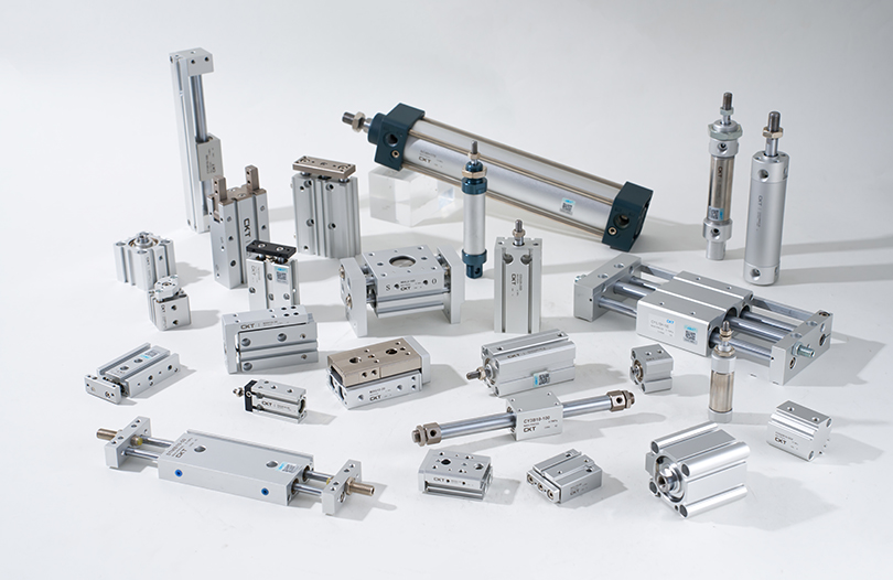
Types of Air Actuator Cylinders: A Complete Classification
Understanding the variety of air cylinder configurations is the first step toward correct selection. Each type addresses a different motion requirement, force profile, and space constraint.
Single-Acting Air Cylinder
Uses compressed air to extend the piston rod in one direction; a return spring (or gravity) retracts it. Common in clamping, stamping, and spring-return valve actuation. Bore sizes typically range from 10 mm to 320 mm. Because only one port needs air, plumbing is simpler, but the return spring reduces usable stroke length and net thrust.
Double-Acting Air Cylinder
Air is alternately supplied to both sides of the piston, producing powered motion in both directions. This is the most common air actuator cylinder type in modern automation. Full-stroke force is available in both extend and retract directions, and stroke lengths can be very long (up to 3,000 mm or more in standard catalog models). Supply pressure: 0.05–1.0 MPa (standard ISO 6431).
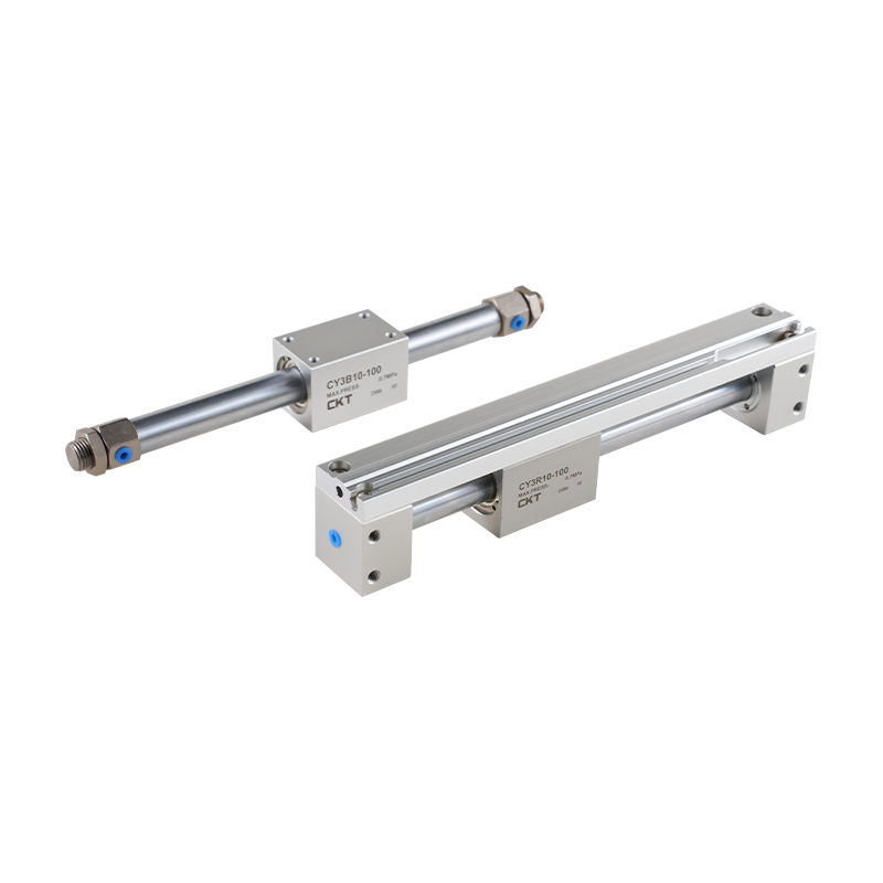
Rodless Air Cylinder
The piston travels inside a slotted or magnetically coupled tube, moving an external carriage without a protruding rod. This design saves installation space—critical in long-stroke applications where a conventional rod would extend the machine envelope by twice the stroke. Stroke lengths up to 6,000 mm are standard from major manufacturers (Festo, SMC, Parker).
Guided (Non-Rotating) Air Cylinder
Incorporates external guide rods or a twin-rod design to prevent piston rotation and handle side loads. Widely used in pick-and-place, drilling fixtures, and pressing applications where precise alignment under off-axis load is critical. Available as round-body or profile-body (compact) variants.
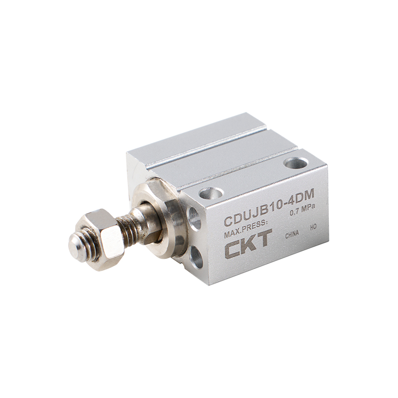
Compact / Short-Stroke Air Cylinder
Designed for installation where axial space is constrained. Stroke lengths are typically 1–50 mm. Round-body or profile-body construction. Popular in semiconductor handling, medical devices, and small gripper mechanisms. Example: SMC CQ2 series offers bore 12–100 mm with stroke 5–100 mm in a profile housing only 27 mm tall.
Rotary Air Actuator
Converts compressed air into a defined rotary output angle (typically 90°, 180°, or 270°). Rack-and-pinion or vane designs are common. Used for quarter-turn valve actuation, part orientation, and door latching. Torque output at 0.6 MPa ranges from 0.5 N·m (small vane type) to over 5,000 N·m (large rack-and-pinion for industrial valve automation).
Tandem Air Cylinder
Two pistons on a single rod, operating in series in the same bore. Output thrust is approximately doubled compared with a single piston at the same bore size and pressure, while the bore diameter is kept small. Used where high force is needed in a compact bore—common in brake systems and high-force clamping.
Bellows / Diaphragm Air Actuator
Uses a flexible rubber or elastomeric element instead of a hard piston. Near-zero friction, very short strokes (1–25 mm), and high sensitivity make these ideal for process control valves, vibration isolation, and precision positioning. Not a "cylinder" in the traditional sense but falls under the broader category of air actuator.
Air Cylinder Force Calculations: The Formulas You Actually Need
Selecting an air actuator cylinder without verifying force output leads to under- or over-sized components. The calculations are straightforward once you understand the geometry.
Extend Force (Full Bore Side)
F_extend = (π / 4) × D² × P
Where D = bore diameter (m), P = supply pressure (Pa). Example: 63 mm bore at 0.6 MPa → F = 0.7854 × (0.063)² × 600,000 = 1,868 N (≈ 190 kgf).
Retract Force (Rod Side)
F_retract = (π / 4) × (D² − d²) × P
Where d = rod diameter (m). For the same 63 mm bore with a 20 mm rod: F = 0.7854 × (0.063² − 0.020²) × 600,000 = 1,680 N. The rod-side area is always smaller, so retract force is always less than extend force.
Effective (Load) Force with Efficiency Factor
Real-world seal friction and lubrication losses reduce theoretical force by roughly 10–15%. Apply a load factor of 0.7–0.8 (some references use 0.5 for intermittent duty with horizontal orientation, per Festo's Pneumatic Handbook, 5th ed.).
F_effective = F_theoretical × η (η ≈ 0.7–0.8)
| Bore Dia. (mm) | 0.4 MPa (N) | 0.6 MPa (N) | 0.8 MPa (N) | 1.0 MPa (N) |
|---|---|---|---|---|
| 20 | 126 | 188 | 251 | 314 |
| 32 | 322 | 483 | 644 | 804 |
| 50 | 785 | 1,178 | 1,571 | 1,963 |
| 63 | 1,245 | 1,868 | 2,491 | 3,117 |
| 80 | 2,011 | 3,016 | 4,021 | 5,027 |
| 100 | 3,142 | 4,712 | 6,283 | 7,854 |
| 125 | 4,909 | 7,363 | 9,817 | 12,272 |
| 160 | 8,042 | 12,063 | 16,085 | 20,106 |
Air Consumption Calculation
Knowing how much compressed air a cylinder consumes per cycle is critical for sizing your compressor and air treatment equipment.
Q (L/cycle) = [(π/4) × D² × L × (P_gauge + P_atm)] / P_atm
Where L = stroke (m), P_gauge = gauge pressure (Pa), P_atm = 101,325 Pa. For a 63 mm bore, 200 mm stroke, at 0.6 MPa: Q ≈ 0.7854 × 0.063² × 0.2 × (600,000 + 101,325) / 101,325 = 2.7 L per single stroke (referenced from Festo Pneumatics Workbook, v5.0).
How to Select the Right Air Actuator Cylinder: 8 Critical Parameters
The wrong air cylinder selection results in premature seal failure, inadequate thrust, or excessive energy consumption. Work through each parameter below before specifying a model.
01
Required Output Force
Calculate the theoretical force needed (see formulas above), then divide by the efficiency factor (0.7–0.8). Add a safety margin of 25–50% for dynamic loads. The resulting value determines the minimum bore size at your operating pressure.
02
Stroke Length
Measure the required travel distance carefully. Longer strokes require rod buckling analysis—use Euler's column formula or manufacturer-provided load charts. As a rule of thumb, strokes exceeding 10× the rod diameter require a guided cylinder or an external guide rail to prevent rod bending under side load.
03
Operating Pressure Range
Most standard air cylinders operate between 0.05 and 1.0 MPa. Compact and miniature cylinders may have lower maximum pressure ratings (0.7 MPa). High-pressure variants are available for 1.5–2.0 MPa applications but require matched seals and valve components.
04
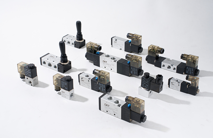
Speed Requirements
Pneumatic cylinder speed is primarily controlled by flow regulators (meter-in or meter-out). Meter-out control (throttling the exhaust) is the standard for smooth motion in most applications. Typical achievable speeds: 50–1,500 mm/s depending on bore size, stroke, and valve flow rate (Cv value). Very high cycle speeds (above 2 cycles/second) require high-flow directional valves and cushioning.
05
Mounting Configuration
ISO 15552 defines standard mounting styles. Common options: foot mount (MF2), flange mount (FF, MF), trunnion mount (MT), clevis (CC), and nose/rod-end pivot (CA). Choose based on load direction, alignment tolerance, and available machine structure.
06
Environmental Conditions
Standard air cylinders use NBR (nitrile) seals rated to −20 °C–+80 °C. For food/beverage or pharmaceutical environments, specify FDA-compliant seals and stainless-steel barrel. For high-temperature processes (up to 200 °C), use FKM (Viton) seals and aluminum or stainless bodies. Corrosive environments may require electroless nickel plating or full 316 stainless construction.
07
Cushioning Requirements
End-of-stroke cushions decelerate the piston before it contacts the end cap, reducing impact and noise. Adjustable needle cushions are standard on most ISO cylinders from 32 mm bore upward. For very fast cycles or heavy loads, external hydraulic shock absorbers may be needed in addition to built-in cushions.
08
Position Detection
Most modern air cylinders feature a T-slot or dovetail groove for magnetic reed or solid-state (Hall-effect) position sensors. Sensors detect the piston magnet through the barrel wall without physical contact. Response time: solid-state sensors respond in under 1 ms; reed switches in 3–5 ms. Choose solid-state for high-speed or dusty environments.
Air Cylinder Applications Across Key Industries
The air actuator cylinder is deployed in virtually every automated manufacturing sector. The following examples illustrate where and how they contribute real process value.
Automotive Manufacturing
Welding fixture clamping, door panel pressing, seat rail testing, and engine assembly positioning. A typical body-in-white welding cell uses 60–120 air cylinders per station. Bore sizes 32–100 mm, strokes 25–300 mm are most common. Cycle rates reach 15–20 per minute in high-volume stamping lines (source: Bosch Rexroth Pneumatics Handbook).
Food and Beverage Packaging
Filling nozzle actuation, cap pressing, labeling, product rejection gates, and conveyor diverters. Stainless-steel or anodized aluminum air cylinders with FDA-compliant seals are required for wash-down zones. Parker's SIDA stainless series and SMC's CG5 clean series are common choices. Operating speeds in packaging typically require 100–500 mm/s with high repeatability.
Semiconductor and Electronics
Wafer handling, probe positioning, component insertion, and PCB test fixtures. Miniature air cylinders (6–16 mm bore) with clean-room compatible materials (zinc-free lubricants, special seals, low particle emission) are used here. SMC's CJP, CJ2, and Festo's ADVU compact series dominate this segment.
Pharmaceutical / Medical Devices
Tablet pressing, blister packaging, syringe filling, and sterile assembly. ISO Class 5 clean-room applications require cylinders with electrostatic dissipative coatings, PTFE-lubricated seals, and traceable material certificates. Cycle life requirements often exceed 50 million cycles.
Logistics and Warehousing
Diverter arms on conveyor sorters, gate actuators in automated storage systems, and parcel stops. Large-bore cylinders (100–200 mm) with long strokes (300–600 mm) handle heavy unit loads. Rodless cylinders are especially practical for horizontal transfer slides in compact sortation systems.
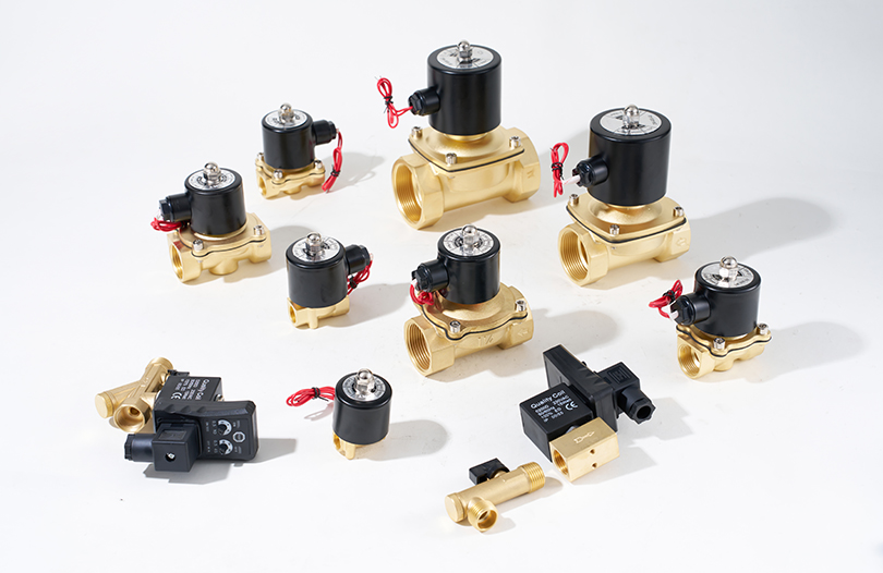
Oil, Gas and Process Industries
Quarter-turn rotary air actuators for pipeline ball valve control; linear air cylinders for emergency shutdown (ESD) actuators. Stainless construction with ATEX/IECEx-rated solenoid valves. Fail-safe spring-return variants guarantee valve closure on air loss—critical for process safety.
Air Cylinder vs. Hydraulic vs. Electric Actuator: Which to Choose?
Selecting among pneumatic, hydraulic, and electric actuators depends on force requirements, precision needs, energy costs, and installation environment. The table below summarizes the key differences from an engineering perspective.
| Parameter | Air Cylinder (Pneumatic) | Hydraulic Cylinder | Electric Actuator |
|---|---|---|---|
| Typical force range | 10 N – 100 kN | 500 N – 10+ MN | 1 N – 50 kN |
| Positional accuracy | End-stops only (± 0.05–0.5 mm with sensors) | Moderate (servo-hydraulic: ± 0.01 mm) | High (± 0.001–0.01 mm) |
| Speed | Very fast (up to 3 m/s typical) | Moderate (0.01–0.5 m/s) | Fast (application-specific) |
| Energy efficiency | Low (15–30% system efficiency) | Moderate (40–60%) | High (70–90%) |
| Initial cost | Low | High (pump, reservoir, valves) | Medium–High |
| Maintenance complexity | Low (FRL unit service) | High (fluid, seals, leaks) | Low–Medium |
| Cleanroom suitability | Yes (with special seals) | No (oil contamination risk) | Yes |
| Explosive environments | Yes (intrinsically safe) | Yes (with care) | Requires ATEX rated motor |
Bottom line: Choose air cylinders when you need fast, repeatable, point-to-point motion at moderate forces in a plant that already has compressed air infrastructure. Choose electric when precision positioning is critical. Choose hydraulic only when forces exceed what pneumatics can achieve in a practical bore size.
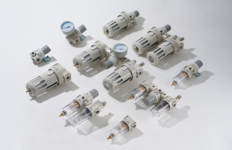
Air Treatment: Why FRL Units Are Not Optional for Air Cylinders
Compressed air from a typical industrial compressor contains moisture, oil aerosols, pipe scale, and particulates. Feeding unfiltered air directly into an air actuator cylinder is the single most common cause of premature seal failure and bore corrosion. An FRL unit (Filter-Regulator-Lubricator) placed upstream of every cylinder circuit is non-negotiable.
Filter
Removes particulates and water condensate from the compressed air stream. Standard filters use 5–40 micron element ratings. For sensitive cylinders (small bore, soft seals), a 5-micron coalescing filter is recommended. Change elements when differential pressure exceeds 0.05 MPa or per manufacturer schedule (typically every 6 months).
Moisture in air at 0.6 MPa and 20°C: up to 22 g/m³. When this air expands at the cylinder, it can deposit water on the bore wall, causing rust and NBR seal swelling within weeks of operation without a filter.
Regulator
Sets and maintains the downstream working pressure regardless of supply pressure fluctuations. Use a precision regulator (accuracy ±0.01 MPa) for force-critical applications. General-purpose regulators maintain ±0.05 MPa. Never set operating pressure higher than the cylinder's maximum rated pressure—most standard aluminum air cylinders are rated to 1.0 MPa; some compact types to 0.7 MPa.
Lubricator (Optional)
Introduces a fine oil mist into the air stream to lubricate cylinder seals and bore. However, most modern air cylinders from major manufacturers (SMC, Festo, Parker) use pre-lubricated, long-life seals and are rated for operation without a lubricator. Adding a lubricator to such cylinders is acceptable but not required—and removes the option to run lubricator-free. If a lubricator is used, ISO VG 32 turbine oil or equivalent is standard. Never use grease-type lubricants in a mist lubricator.
Recommended Air Quality Standard for Air Cylinders
ISO 8573-1:2010 defines compressed air quality classes. For standard pneumatic cylinders, ISO 8573-1 Class 5.4.5 is generally sufficient: particulate size up to 40 µm, pressure dew point below +7°C, oil content below 25 mg/m³. For cleanroom and food-grade cylinders, target Class 1.2.1.
Air Cylinder Maintenance: Schedules, Inspection Points, and Troubleshooting
A properly maintained air actuator cylinder can achieve 50–100 million cycles before major overhaul. Neglected cylinders fail in under 5 million. The difference lies in systematic maintenance and early fault detection.
Routine Maintenance Schedule
| Interval | Task | Acceptance Criterion |
|---|---|---|
| Daily | Visual check for air leaks, rod seal oil film, and condensate drain on filter | No visible leaks; thin oil film on rod (if lubricated); drain not full |
| Weekly | Check FRL lubricator oil level; inspect rod for scratches and corrosion | Oil level above minimum mark; rod surface smooth, no pitting |
| Monthly | Check mounting fastener torque; verify cushion adjustment; clean external rod wiper | Fasteners at specified torque; no end-of-stroke metal contact noise |
| 6 Months | Replace filter element; measure rod runout with dial indicator; check sensor function | Filter element differential pressure under 0.05 MPa; runout under 0.1 mm/100 mm |
| Annual / 10M cycles | Full seal kit replacement; bore inspection; re-lubricate piston and rod seals | Bore surface finish Ra ≤ 0.8 µm; no scoring; all seals replaced with OEM kit |
Common Faults and Causes
- Air leaking at rod seal: Worn or nicked rod seal lip. Inspect rod surface for scratches—even a 50-micron groove causes chronic leakage. Replace seal and refinish or replace rod.
- Slow or erratic extension: Blocked flow control, contaminated piston seal, or inadequate supply pressure. Disconnect from load and test free-run speed—if normal, the issue is load-related or mechanical binding.
- Cylinder will not retract: Faulty directional control valve (not switching to retract port), back-pressure from load exceeding retract force, or jammed piston. Check valve electrically first.
- Excessive end-of-stroke impact noise: Cushion needle screwed too far out (over-opened). Adjust needle in small increments until impact noise stops. Over-adjusted cushions trap air and cause force loss near end of stroke.
- Internal leakage (air bypassing piston): Worn piston seal. Detect by disconnecting one port to atmosphere—if air blows through with the other port pressurized, the piston seal is bypassing. Requires disassembly and seal replacement.
- Rod corrosion: Moisture in air supply combined with no lubrication. Upgrade to coalescing filter and check dew-point. Short-term: apply a thin coat of VG32 oil manually to the rod weekly until the air quality issue is resolved.
Key International Standards for Air Actuator Cylinders
Standardization in pneumatic cylinders ensures interchangeability between manufacturers, simplifies spare-parts management, and defines minimum quality thresholds. The standards below are the most referenced in global procurement and engineering.
ISO 6431
The dominant global standard for round-body pneumatic cylinders. Defines bore sizes (8–320 mm), stroke increments, interface dimensions (ports, mounting holes, rod-end threads), and test pressures. Most branded cylinders from Festo, SMC, Parker, Bimba, and Aventics conform to this standard—enabling true cross-brand dimensional interchangeability.
ISO 15552
Extends ISO 6431 to profile-body (tie-rod style) cylinders, which offer mounting accessories that are interchangeable across all compliant manufacturers. Bore sizes 32–320 mm. The most widely used standard for general industrial automation cylinders globally.
ISO 21287
Covers compact cylinders with bore sizes 8–100 mm and reduced overall length. Addresses the growing need for space-saving actuators in modern machine design without sacrificing interchangeability.
ISO 4414
Safety code of practice for pneumatic systems, covering design, installation, and maintenance requirements for all pneumatic equipment including air cylinders. Mandates pressure relief, safe working pressure marking, and maintenance accessibility.
NFPA T3.6.7 (North America)
The American equivalent standard covering pneumatic cylinder dimensions. NFPA cylinders have slightly different porting and mounting interfaces from ISO cylinders—important to verify when replacing components in North American-built machinery.
Reducing Compressed Air Costs: Energy Efficiency for Air Cylinder Systems
Compressed air is one of the most expensive energy forms in manufacturing—the U.S. Department of Energy estimates that compressed air systems account for 24% of industrial motor-driven electricity in the U.S., and leakage alone wastes 20–30% of compressor output in a typical plant. Optimizing your air cylinder circuits is a high-return exercise.
Practical Energy Reduction Strategies
- Right-size the bore: Oversized cylinders waste air on every cycle. A 100 mm bore cylinder uses 4× the air of a 50 mm bore at the same stroke. Recalculate force requirements with actual efficiency factors before specifying large bores.
- Use pressure reduction on retract stroke: If the retract load is lower than extend load, supply the rod side at reduced pressure using a secondary regulator. This alone can reduce per-cycle air consumption by 15–25% in many double-acting applications.
- Minimize dead volume (tube length): Every meter of 8 mm tubing between a valve and cylinder adds 50 cm³ of dead volume per cycle. Locate directional control valves as close as possible to the cylinder ports—ideally under 300 mm away.
- Audit and repair leaks systematically: An ultrasonic leak detector (e.g., Fluke ii900) can locate leaks as small as 0.1 mm diameter at 0.6 MPa. A 1 mm leak at 0.7 MPa wastes approximately 1.4 m³/h of compressed air—at USD 0.02/m³, that is USD 245/year per leak point.
- Consider air-saving circuits: Some valve manifold systems allow exhaust air from the retract stroke to be partially recycled as supply to the extend stroke, reducing total air consumption by up to 30% in high-cycle applications (source: Festo Energy Efficiency in Pneumatic Systems, white paper 2022).
Air Actuator Cylinder Buying Guide: What to Verify Before Ordering
Procurement decisions for pneumatic cylinders are often driven by price without examining the total lifecycle cost. The following checklist covers the critical technical details that separate a cost-effective specification from a future maintenance headache.
Confirm Bore and Stroke Dimensions
Verify that the bore and stroke match your force and travel requirements after applying efficiency and safety factors. Confirm the maximum stroke available for the specific bore—longer strokes may require special ordering or a guided variant.
Specify Seal Material
Default NBR seals cover most applications. For temperatures above 80°C specify FKM; for food contact specify EPDM or PTFE; for extreme cold (below −20°C) specify polyurethane or silicone. Seal material is often configurable at time of order with no lead-time penalty from major manufacturers.
Verify Port Size and Thread Type
ISO 6431 cylinders use metric ports (M5, G1/8, G1/4, G3/8, G1/2). NFPA cylinders use NPT ports. If your facility uses existing NPT-plumbed systems, specifying the wrong thread type means every fitting needs a mismatched adapter—a hidden cost that adds up quickly across 50+ cylinders.
Check Sensor Compatibility
If you need position sensing, confirm the cylinder barrel has a compatible switch mounting slot (T-slot, C-slot, or band clamp) and that the sensor you've selected (NPN/PNP, 2-wire/3-wire, DC/AC) matches the PLC input module. Many integration delays stem from sensor-cylinder slot incompatibility discovered at installation.
Confirm Cushion Type
Adjustable cushions are standard from 32 mm bore upward on most ISO cylinders. Non-cushioned cylinders (NC) are available for very fast short-stroke applications where external shock absorbers handle end-of-stroke deceleration. Specify NC only if you've accounted for deceleration at the system level.
Consider Lifecycle Cost, Not Unit Price
A no-name air cylinder at 40% of the price of an SMC or Festo equivalent may have a seal life of 2–5 million cycles vs. 20–50 million for the branded alternative. In a 10-cycle/minute application, that is a replacement every 3–4 months vs. every 3–5 years. Factor in downtime cost, labor, and spare parts inventory before deciding on price alone.
Frequently Asked Questions About Air Actuator Cylinders
What is the difference between an air cylinder and a pneumatic cylinder?
There is no functional difference. "Air cylinder," "pneumatic cylinder," and "air actuator cylinder" all refer to the same device—a mechanical actuator driven by compressed air. "Pneumatic cylinder" is the more formal engineering term; "air cylinder" is widely used in industrial maintenance and procurement contexts. Both terms appear interchangeably in manufacturer catalogs from SMC, Festo, Parker, and others.
How long does an air cylinder last?
Seal life—the primary wear item—ranges from 5 million cycles (basic-grade cylinders with poor air quality) to 100+ million cycles (premium cylinders with clean, dry air and proper lubrication). The barrel and rod are designed for the service life of the machine, provided they are not scratched or corroded. In practice, an industrial air cylinder in a well-maintained system should run 3–7 years before seal replacement at typical automation cycle rates of 10–30 cycles/minute. Source: Festo Pneumatics Technical Catalogue, 2023.
What pressure should I run my air cylinder at?
Most standard air cylinders are rated to 1.0 MPa (145 PSI). However, running at the maximum rating is not optimal. The most energy-efficient approach is to set pressure at the lowest level that provides the required force with a 25% safety margin—typically 0.4–0.6 MPa for most applications. Higher pressure increases energy costs, accelerates seal wear, and raises exhaust noise levels without improving speed (speed is controlled by flow rate, not pressure).
Can I use an air cylinder without a lubricator?
Yes, for most modern cylinders. Major manufacturers (SMC, Festo, Parker) pre-lubricate their cylinders with long-life grease and design them to operate without a downstream lubricator for the rated service life, provided air quality meets ISO 8573-1 Class 5 or better. If a lubricator is installed after a non-lubricated cylinder has run in, do not remove it—the oil mist washes away the factory-applied grease and the cylinder becomes dependent on continuous lubrication to prevent premature seal wear.
What causes an air cylinder rod to extend slowly?
The most common causes are: (1) the flow control valve on the exhaust port (meter-out) is closed too far—open it gradually; (2) supply pressure is below the required minimum for the load—verify pressure at the cylinder port, not just at the FRL; (3) the piston seal is worn and bypassing air internally—test by pressurizing with load disconnected; (4) a kinked or undersized supply tube is restricting flow—6 mm tube limits flow to about 50 L/min free air at 0.6 MPa, insufficient for large bore cylinders at high speeds.
What is a double-acting vs. single-acting air cylinder?
A double-acting air cylinder uses compressed air to drive the piston in both extend and retract directions, giving full controlled force in both directions with two air ports. A single-acting cylinder uses air for one direction only (usually extend) and relies on a return spring or gravity for the opposite direction. Single-acting cylinders are simpler to plumb (one port) but lose some stroke to the spring space and provide no controlled retract force. Double-acting cylinders are the standard choice for most automation applications.
How do I prevent my air cylinder from rotating?
Standard round-body cylinders have no anti-rotation feature on the rod. If rod rotation is a problem, the solutions are: (1) use an external guide rail or guide rod assembly; (2) specify a guided cylinder (twin-rod or profile-body type with integrated guide); (3) add a rotation prevention accessory (typically a flat key or anti-rotation collar matched to the cylinder's thread). SMC's CQ2 and Festo's ADN series offer optional anti-rotation versions without a full guided cylinder upgrade.
Is it possible to control an air cylinder's stopping position mid-stroke?
Standard pneumatic cylinders are point-to-point devices—they stop reliably only at end stops. Mid-stroke stopping with a pneumatic cylinder is possible with a 3-position center-closed or center-exhaust directional valve, but position is not repeatable due to air compressibility. For repeatable mid-stroke positioning, the industry standard is to use either (a) an electric linear actuator, (b) a servo-pneumatic system with a proportional valve and linear position feedback (accurate to ±0.1 mm), or (c) a fixed-position stop tube within the cylinder to define a second stop position.
What is the maximum stroke available for a standard air cylinder?
Standard catalog air cylinders are typically available with strokes up to 1,000–2,000 mm from major manufacturers. Beyond that, rodless cylinders extend the practical stroke range to 5,000–6,000 mm (and in custom versions, further still). For very long strokes with conventional rod cylinders, rod buckling analysis (Euler's formula) is mandatory—a long thin rod under compressive load will buckle before the rated cylinder force is reached, and the safe load drops quickly with stroke length.
How do I choose between a round-body and profile-body (tie-rod) air cylinder?
Round-body (ISO 6431) cylinders are compact, lightweight, and have a simple external surface—ideal for space-constrained mounting and general applications where sensor mounting accessories are limited. Profile-body (ISO 15552 / tie-rod) cylinders have a T-slot profile on all four sides for easy accessory mounting (sensors, brackets, stop valves), a full range of ISO-standard mounting brackets, and are generally easier to service. For most general industrial automation with bore sizes 32 mm and above, the profile-body cylinder is the practical default choice due to its accessories ecosystem.


