


Content
- 1 What Is an Angular Air Gripper Cylinder and How Does It Work
- 2 Key Specifications That Define Angular Air Gripper Cylinder Performance
- 3 Angular Air Gripper Cylinder vs. Parallel Air Cylinder Gripper: Which to Choose
- 4 How to Size an Angular Air Gripper Cylinder for Your Application
- 5 Mounting Configurations for Angular Air Gripper Cylinders in Automation Cells
- 6 Sensor Integration and Position Detection on Angular Air Gripper Cylinders
- 7 Fingertip and Jaw Design for Angular Air Gripper Cylinders
- 8 Where Angular Air Gripper Cylinders Are Used Across Industries
- 9 Maintenance, Troubleshooting, and Service Life Extension for Angular Air Gripper Cylinders
- 10 Compressed Air Quality and Supply Requirements for Angular Air Gripper Cylinders
- 11 Angular Air Gripper Cylinder Selection Checklist Before You Order
- 12 Frequently Asked Questions About Angular Air Gripper Cylinders
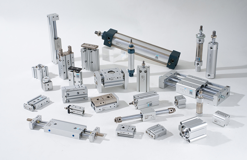
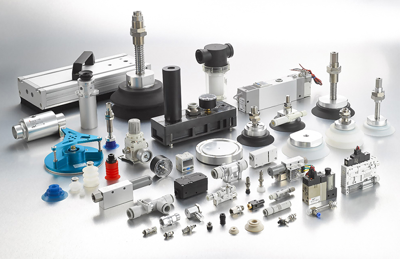
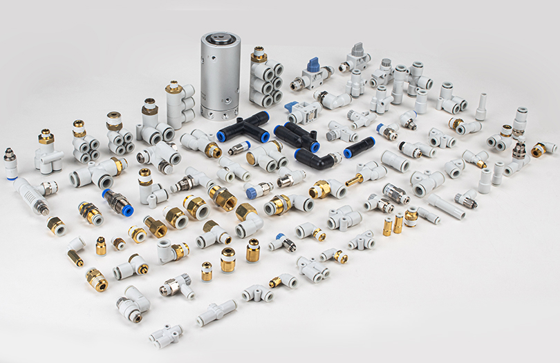
Pneumatic Automation
An angular air gripper cylinder — also called a rotary or swing gripper cylinder — combines a rotary air cylinder with a parallel or angular jaw mechanism to grip, rotate, and release workpieces in a single compact unit. Unlike a conventional straight air cylinder that only pushes or pulls in one axis, the angular type swings its jaws open and closed along an arc, making it the go-to choice for pick-and-place cells, assembly stations, and transfer systems where linear grippers simply cannot fit or cannot reorient the part fast enough.
On a practical level, the decision to use an angular air gripper cylinder over other pneumatic or electric gripping methods comes down to three factors: gripping force (typically 20 N to 1,200 N depending on bore size), the angular sweep of the jaws (commonly 10°, 20°, 30°, 40°, or custom), and the overall envelope that the air cylinder occupies inside the machine cell. Once you understand those three parameters, selecting the right angular gripper cylinder becomes straightforward.
Core Concept
What Is an Angular Air Gripper Cylinder and How Does It Work
An angular air gripper cylinder is a pneumatic device that uses compressed air to drive an internal piston. The piston motion is converted — through a rack-and-pinion, wedge-cam, or lever mechanism — into a symmetrical angular opening and closing of two or more gripping jaws. The term "air cylinder" is used because the actuating force comes entirely from pressurized air, typically between 0.15 MPa and 0.8 MPa (roughly 22 to 116 psi), flowing through an inlet port and acting on a piston area.
Rack-and-Pinion Drive
Compressed air moves the piston, which carries a rack that meshes with a pinion gear on each jaw shaft. Both jaws rotate simultaneously and symmetrically. This is the most common configuration in angular air gripper cylinders because it delivers a consistent grip center regardless of jaw opening angle.
Wedge-Cam Drive
A wedge-shaped cam rider on the piston rod pushes two floating rollers outward or inward, pivoting the jaw arms. This design is especially rigid under side loads and is common in heavy-duty angular gripper air cylinders handling parts above 2 kg.
Lever-Link Drive
A link arm connects the piston to each jaw. The lever geometry amplifies force at the jaw tip and is used when the air cylinder bore must stay small but gripping force at the fingertip must remain high — useful in cleanroom or compact automation.
Regardless of drive type, the air cylinder body houses seals, the piston, the jaw guides, and the mounting base. Standard bodies are made from anodized aluminum alloy, while the jaws and internal cam or rack components are typically hardened steel. The gripper connects to the rest of the machine via a standard mounting flange or T-slot rail adapter on the back of the air cylinder body.
Specifications
Key Specifications That Define Angular Air Gripper Cylinder Performance
Selecting the right angular air gripper cylinder requires matching multiple specification parameters to the actual load. The table below summarizes the most critical parameters and their typical ranges across mainstream catalog products from suppliers such as SMC, Festo, SCHUNK, and Pneumax.
| Parameter | Small Series | Medium Series | Large Series |
|---|---|---|---|
| Bore Diameter | 6 – 16 mm | 20 – 32 mm | 40 – 80 mm |
| Gripping Force per Jaw | 20 – 80 N | 90 – 350 N | 400 – 1,200 N |
| Angular Jaw Stroke | 10° – 30° | 20° – 40° | 20° – 40° |
| Operating Pressure | 0.15 – 0.7 MPa | 0.15 – 0.8 MPa | 0.2 – 0.8 MPa |
| Cycle Life (rated) | 5 – 10 million | 10 – 30 million | 15 – 50 million |
| Repeatability | ± 0.03 mm | ± 0.02 mm | ± 0.01 mm |
Two numbers that trip up engineers most often are gripping force at the jaw tip versus at the jaw root. Because the jaw is a lever, the force drops as the contact point moves further from the pivot. Most catalog data gives force at the jaw root (closest to the pivot). If your fingertip adapter extends the jaw by 30 mm from the root, expect the effective gripping force to drop by 30–50% depending on jaw geometry. Always request the jaw moment diagram from the supplier, not just the headline force figure.
Cycle life for an air cylinder in a gripper application also depends on lubrication. Most modern angular air gripper cylinders ship with permanently lubricated piston seals and can run on clean, dry, oil-free compressed air — but if the air supply carries oil mist, compatibility with the seal compound must be verified. NBR seals tolerate standard mineral oil mist; FKM (Viton) seals are preferred for applications using synthetic lubricants or for environments with elevated temperatures above 60 °C.
Comparison
Angular Air Gripper Cylinder vs. Parallel Air Cylinder Gripper: Which to Choose
Angular Type
- Jaws rotate along an arc — jaw tips travel more distance for the same body size
- Better suited for picking parts from a nest, bowl feeder, or conveyor edge where the jaw must swing clear
- Jaw opening at the tip is proportional to the pivot radius, so larger fingertips dramatically increase the effective opening without changing the air cylinder bore
- Force at the jaw tip is lower than at the pivot; wedge-cam models partially compensate this
- Performs well on conical, spherical, or irregularly shaped parts
- Slightly more complex finger design required to match a precise part geometry
Parallel Type
- Jaws translate linearly — the grip centerline stays constant regardless of jaw opening width
- Ideal for prismatic (rectangular or cylindrical) parts where both faces are parallel
- Force at the jaw face is nearly equal to the piston force; no lever-arm loss
- Jaw opening range is limited by the physical stroke of the air cylinder piston
- Centering accuracy is inherently high — both jaws move equal distances from center
- Less flexible when part sizes vary significantly between products on the same line
A common rule of thumb in pneumatic automation: if the ratio of jaw opening to body length needs to exceed 1:3, an angular air gripper cylinder almost always wins on space efficiency. If absolute centering repeatability below ± 0.01 mm is the priority and part geometry is prismatic, a parallel air cylinder gripper remains the better choice. In mixed production cells, some designers mount an angular air gripper cylinder on one robot wrist and a parallel gripper on another to cover both scenarios without retooling.
Engineering Guide
How to Size an Angular Air Gripper Cylinder for Your Application
Sizing an angular air gripper cylinder correctly is the single most important step before purchase. Undersized units drop parts; oversized units waste money, consume more compressed air, and create unnecessary inertia on the robot wrist. The sizing process has four steps.
Step 1 — Define the Required Gripping Force
Start with the part mass and the maximum acceleration the gripper will experience during the pick-and-place cycle. A basic formula from SMC's gripper selection guide states:
Required grip force = Part mass (kg) × (Gravity + Peak acceleration) × Safety factor
For a 0.5 kg part under 5 m/s² acceleration and a 3× safety factor: Required grip = 0.5 × (9.81 + 5) × 3 = 22.2 N per jaw. A small-bore angular air gripper cylinder with a 16 mm bore at 0.5 MPa supply pressure delivers approximately 60 N per jaw at the root — well within range, with margin for fingertip lever-arm loss.
Step 2 — Determine the Required Jaw Opening Angle
Measure the maximum part diameter or width plus any clearance needed for the jaw to swing past the part without contact. Most applications use 30° to 40° total jaw opening (15° to 20° per jaw from center). If the part changes between models, select an angular air gripper cylinder whose maximum opening comfortably exceeds the largest part, then use adjustable stop bolts or sensor-triggered valve switching to control the open position for smaller parts.
Step 3 — Check the Allowable Moment Load on the Air Cylinder Body
Angular air gripper cylinders specify three allowable moment values: My (pitch), Mx (roll), and Mz (yaw). These limits come from the jaw guide bearing span inside the air cylinder. Exceeding these moments causes premature wear of the jaw slides or catastrophic jaw jam. At a minimum, calculate the static moment from the heaviest fingertip adapter plus the gripped part at the worst-case distance from the air cylinder body face.
Step 4 — Verify Air Consumption and Supply Line Sizing
Each actuation of the angular air gripper cylinder displaces a volume of air equal to the piston bore area × piston stroke × 2 (for open and close). At 10 cycles per minute and a 20 mm bore unit, air consumption is approximately 0.4 to 0.8 L/min at 0.5 MPa — negligible for a single gripper, but multiply by 30 grippers on a large assembly line and the compressed air system must be sized accordingly. Undersized air supply lines cause slow cycle times, pressure drops, and inconsistent gripping force across the line.
Installation
Mounting Configurations for Angular Air Gripper Cylinders in Automation Cells
The mounting interface of an angular air gripper cylinder must align with both the robot flange or tooling plate and the required jaw orientation relative to the part. Manufacturers offer several standard mounting options, and understanding each saves significant rework during cell integration.
A
Face (Flange) Mount
The most common option. Four or six threaded holes on the front face of the air cylinder body accept cap screws directly into the tooling plate or robot wrist adapter. This orientation puts the jaw swing in the plane perpendicular to the mounting face — standard for top-of-part pickup in vertical axis pick-and-place cells.
B
Side (Body) Mount
Threaded holes or T-slot channels on the side of the air cylinder body allow mounting perpendicular to the jaw swing axis. Used when the gripper must approach the part from the side, such as in horizontal transfer stations or when vertical stack height must be minimized.
C
Through-Hole (Center Pivot) Mount
A centered through-bore in the angular air gripper cylinder body allows the unit to swivel on a shaft during multi-axis transfer. Less common but critical in rotary dial machines where the gripper must change its own orientation between stations.
D
Trunnion Mount
A pair of trunnion pins on the sides of the air cylinder body allows free pivoting of the gripper during gripping — useful on parts with variable thickness that would bind a rigidly mounted gripper. The air cylinder "floats" to self-align, then the fingertips lock on the part surface.
Port location is just as important as body mounting. Most angular air gripper cylinders offer ports on multiple faces of the air cylinder body, with plugs closing the unused ports. Selecting the correct active port face during ordering prevents tubing congestion inside a tight robot wrist envelope and reduces the risk of tube kinking, which is a common cause of sporadic gripper failures in high-cycle applications.
Sensing & Control
Sensor Integration and Position Detection on Angular Air Gripper Cylinders
Most angular air gripper cylinders accept reed switch, Hall-effect, or magneto-resistive sensors in dedicated T-slots machined directly into the air cylinder body. These sensors detect a permanent magnet embedded in the piston and signal the PLC when the jaws have reached the open or closed position. Proper sensor selection and placement is one of the most overlooked aspects of gripper integration — yet it directly determines whether the machine can detect part drop, part absence, or gripper jam conditions before they cause a line stoppage.
Reed Switch
Simple, low-cost, and compatible with 5–240 V DC/AC circuits. Response time is approximately 1–3 ms. The main limitation is mechanical contact wear — at 10 million cycles, reed switches can develop contact bounce. Best used in lower-cycle applications or where budget is the primary concern.
Hall-Effect Sensor
Solid-state, no moving parts. Response time of 0.1–1 ms and rated for 100 million+ operations. Available in NPN and PNP output, 2-wire and 3-wire versions. Preferred for high-cycle angular air gripper cylinders in automotive or electronics assembly lines where the gripper may cycle 20+ times per minute for multiple shifts.
Analog Position Sensor
Some advanced angular air gripper cylinder designs use a linear magneto-resistive strip to output a continuous 0–10 V or 4–20 mA analog signal proportional to piston position. This allows the PLC to detect partial closure, confirming that the gripped part is between the minimum and maximum size limits — a powerful quality check that digital sensors cannot provide.
When positioning sensors, place the closed-position sensor so that the signal triggers only after the jaws have fully closed on the actual part — not on the mechanical stop inside the air cylinder. If the sensor fires on the mechanical stop, a dropped part goes undetected until downstream inspection, causing a defective assembly escape. Many line engineers use both a closed-position sensor set to fire on the part and a mechanical stop sensor set 1–2 mm beyond to confirm full piston travel — the difference between the two signals confirms whether a part is present and within nominal size tolerance.
Tooling
Fingertip and Jaw Design for Angular Air Gripper Cylinders
The angular air gripper cylinder body provides the actuation; the fingertips determine whether the gripper actually does its job. Poorly designed fingertips are responsible for the majority of gripper-related line stoppages in practice — not the air cylinder itself. Fingertip design must address four issues: contact geometry, material, mass, and replaceability.
Contact Geometry
Because the jaw swings along an arc, the contact point on the part traces a curved path as the gripper closes. For cylindrical parts, a V-groove cut into the fingertip at the correct included angle (typically 60° or 90°) causes the arc motion to self-center the part even if it is slightly offset in the nest. For flat-sided parts, the fingertip face must be angled to remain tangent to the arc at the closed position — otherwise the jaw face scrapes against the part surface as it closes, causing surface damage and particle generation.
Fingertip Material Selection
For general industrial parts, hardened tool steel (HRC 52–58) fingertips provide the best wear life. For polished or coated surfaces that must not be scratched, polyurethane or PEEK inserts reduce contact pressure while maintaining grip. In food-grade or pharmaceutical applications, all wetted fingertip surfaces must comply with relevant material requirements — typically 316L stainless steel or medical-grade PEEK — and the air cylinder body itself should be specified in a corrosion-resistant version.
Mass Budget for the Fingertip
Every gram added to the fingertip increases the bending moment on the jaw shaft inside the air cylinder. The allowable jaw moment (My) from the angular air gripper cylinder datasheet sets the absolute limit. As a working rule, keep total fingertip plus part mass below 30% of the rated My allowable to leave enough margin for dynamic loads during acceleration and jerk. Carbon-fiber or aluminum fingertips can reduce mass by 60–70% compared to steel alternatives at equivalent cross-sectional strength — worth considering when the air cylinder approaches its moment limit.
Quick-Change Fingertip Systems
In flexible manufacturing cells where the same angular air gripper cylinder handles multiple part families, quick-change fingertip systems reduce changeover time from 15–20 minutes per gripper (traditional bolted fingertips) to under 30 seconds. SCHUNK, SMC, and Festo all offer proprietary quick-change systems compatible with their angular gripper cylinder bodies, using ball-lock or bayonet mechanisms that automatically locate and lock the finger without tools.
Industry Use Cases
Where Angular Air Gripper Cylinders Are Used Across Industries
Angular air gripper cylinders appear in virtually every sector that uses pneumatic automation. The following industry breakdowns illustrate why the angular configuration is chosen over simpler straight air cylinder or parallel gripper alternatives in each context.
Automotive Assembly
Engine block machining lines use angular air gripper cylinders to pick bearing shells, valve seats, and piston rings from bowl feeders. The angular jaw sweep allows the gripper to reach into a vibrating bowl at an angle and extract a single part without disturbing adjacent parts — a task that would require a much longer linear air cylinder stroke with a parallel gripper, adding unwanted inertia on the robot wrist.
Electronics Manufacturing
SMT (surface-mount technology) lines use miniature angular air gripper cylinders with bores as small as 6 mm to handle connectors, semiconductor packages, and small capacitors. At these scales, the angular type provides a wider jaw opening relative to body size than any parallel air cylinder gripper, which is critical when picking from closely spaced component trays.
Pharmaceutical Packaging
Blister pack and bottle handling lines use angular air gripper cylinders in stainless-steel or anodized versions to pick cylindrical containers from conveyor lanes. The self-centering action of V-groove fingertips on the angular gripper eliminates the need for precision part-positioning fixtures upstream of the gripper — a significant cost saving on high-volume lines.
Food Processing
Pick-and-place robots in bakery and confectionery lines use angular air gripper cylinders with silicone fingertips to handle items with irregular shapes — bread rolls, pastries, wrapped bars. The angular sweep allows the jaw to conform around irregular profiles in a way that a flat-faced parallel air cylinder gripper cannot without custom tooling for each SKU.
Plastics Injection Molding
Parts removal robots use angular air gripper cylinders to extract molded parts from the mold cavity immediately after ejection. The angular jaw allows the gripper to enter the mold tool at an angle, close around the still-warm part, and retract without contacting the mold surface — protecting expensive tooling from impact damage caused by a mis-timed linear air cylinder stroke.
Medical Device Assembly
Catheter tube assembly, syringe barrel insertion, and needle shield placement all use small-bore angular air gripper cylinders to handle delicate, thin-walled components. The low minimum operating pressure of some units (as low as 0.15 MPa) allows very gentle gripping without deforming or cracking fragile medical components.
Maintenance
Maintenance, Troubleshooting, and Service Life Extension for Angular Air Gripper Cylinders
A well-maintained angular air gripper cylinder running on clean compressed air at rated pressure should reach its rated cycle life without internal service. The practical reality on the factory floor is that contaminated air, over-pressurized supply lines, and mechanical abuse from misloaded parts are the three most common life-shortening factors. Understanding the failure modes helps maintenance teams intervene before a complete gripper failure stops the line.
Common Failure Modes and Diagnostic Steps
- Slow jaw speed or incomplete closing: First check supply pressure at the gripper port (not at the compressor). A pressure drop of more than 0.05 MPa between the regulator and the gripper port indicates undersized tubing or a partially blocked filter. Second, check the speed controller (flow control valve) on the air cylinder supply line — clogged controllers are extremely common and often overlooked.
- Jaw drift in the closed position (part drops without valve signal): This indicates a leaking piston seal inside the air cylinder. Disconnect the exhaust line and listen for air leaking from the exhaust port while the gripper is in the closed position. If air leaks continuously, the piston seal needs replacement. In most angular air gripper cylinders, seal kits are available from the manufacturer and the rebuild procedure takes 15–30 minutes with basic tools.
- Jaw play or backlash increasing over time: Wear in the rack-and-pinion or cam mechanism inside the air cylinder body. Check jaw repeatability with a dial indicator — if positional error has grown beyond twice the rated repeatability, the internal mechanism should be inspected. In severe cases, full gripper replacement is more economical than internal repair.
- Corrosion on the jaw guides or body exterior: Caused by condensate in the compressed air or aggressive washdown chemicals in food/pharma applications. Install a refrigerant air dryer upstream and verify that the selected angular air gripper cylinder body material and surface treatment are appropriate for the chemical environment.
Preventive Maintenance Schedule
| Interval | Task | Target Condition |
|---|---|---|
| Daily | Verify sensor signals and cycle count on PLC | No missed signals; cycle count incrementing |
| Weekly | Check supply pressure at gripper port; inspect tubing for kinks | Pressure within ± 0.02 MPa of setpoint |
| Monthly | Clean exterior of air cylinder body; check fingertip fastener torque | No coolant/oil contamination; no loose fasteners |
| 6 Months | Verify jaw repeatability with dial indicator; clean air filter element | Repeatability within rated specification |
| At Rated Cycle Life | Full overhaul or replacement; seal kit installation | Air cylinder performance restored to new specification |
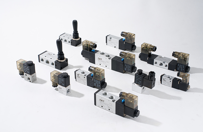
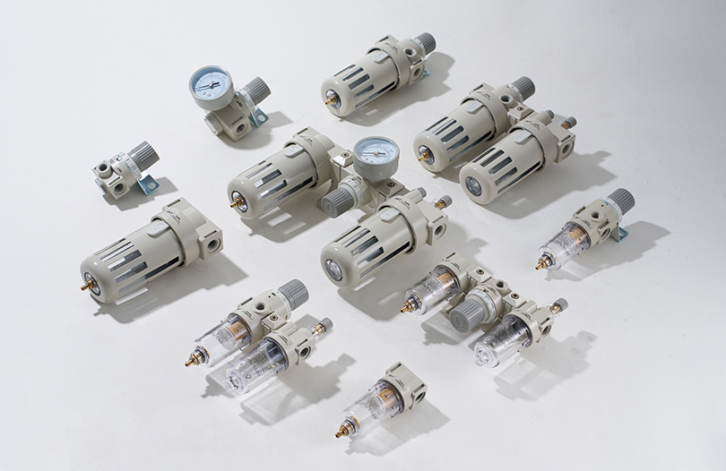
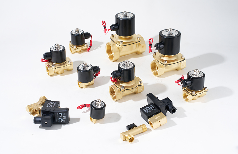
Pneumatic System
Compressed Air Quality and Supply Requirements for Angular Air Gripper Cylinders
The air cylinder inside an angular gripper is only as reliable as the compressed air feeding it. ISO 8573-1 defines compressed air quality classes, and most angular air gripper cylinder manufacturers specify a minimum air quality class for their products. Understanding these requirements prevents premature seal failure, internal corrosion, and sticky jaw operation caused by particulate contamination.
Particulate Content
Most angular air gripper cylinders require ISO 8573-1 Class 3 or better for solid particles — meaning particles no larger than 5 microns and a maximum concentration of 5 mg/m³. Contamination above this level causes scoring of the piston bore and accelerated seal wear inside the air cylinder. A 5-micron sintered bronze or polyethylene filter immediately upstream of the gripper supply valve is the minimum recommended filtration.
Moisture Content
The pressure dew point of the compressed air should be at least 10 °C below the minimum ambient temperature at the gripper location. In a 20 °C factory, this means a dew point of 10 °C or lower (ISO 8573-1 Class 4) is acceptable, but in a cold storage or outdoor installation, a refrigerant dryer achieving Class 4 or a membrane/desiccant dryer achieving Class 2 may be required to prevent condensate inside the air cylinder.
Oil Content
Modern angular air gripper cylinders with PTFE-coated pistons or permanently lubricated seals can run on completely oil-free air (ISO 8573-1 Class 1 oil content, below 0.01 mg/m³). Running oil-mist lubrication on these units actually degrades performance by washing out the factory grease from jaw guide bearings. If an oil-mist lubricator already exists on the supply line, specify an angular air gripper cylinder with NBR seals rated for oil-lubricated service.
Buyer's Guide
Angular Air Gripper Cylinder Selection Checklist Before You Order
Use this checklist to confirm you have captured all the information needed to specify an angular air gripper cylinder without costly revisions after delivery.
- Part mass and maximum dimensions (length, diameter, weight)
- Peak acceleration and jerk during the pick-and-place cycle (from robot or servo controller data)
- Required jaw opening angle (total, not per jaw) with part in the gripper and part cleared
- Supply pressure available at the gripper location (measure at the installation point, not at the compressor)
- Available envelope dimensions (X × Y × Z) for the air cylinder body plus jaw sweep arc
- Mounting face and port face required (to set tubing routing)
- Required sensor type (reed, Hall-effect, or analog) and output voltage/current standard (NPN/PNP, 24 V DC)
- Operating temperature range and presence of washdown, coolant, or chemical exposure
- Required cycle life (total operations before scheduled replacement or overhaul)
- Fingertip material requirement based on part surface and environment (steel, PEEK, silicone, stainless)
- Whether quick-change fingertip capability is required for multi-part flexibility
- Spare parts and seal kit availability from local distributor (important for minimizing downtime)
FAQ
Frequently Asked Questions About Angular Air Gripper Cylinders
What is the difference between an angular air gripper cylinder and a rotary air cylinder?
A rotary air cylinder rotates a shaft or flange through a defined angle — its output is pure rotation, with no gripping function built in. An angular air gripper cylinder uses an internal mechanism to convert air cylinder piston motion into the symmetrical angular opening and closing of jaws. The "rotary" motion is internal and results in gripping action, not a rotating output shaft. The two devices serve completely different functions and are not interchangeable.
Can an angular air gripper cylinder grip both internally and externally on the same part?
Yes. Most angular air gripper cylinders can be configured for either external gripping (jaws close on the outside of the part) or internal expanding gripping (jaws open into a bore inside the part). The fingertip design determines the grip direction — the air cylinder body and mechanism are identical. Some catalog units include both external and internal fingertip sets in the kit. The gripping force calculation changes because in internal expanding mode, the jaw pushes outward rather than inward, and the reaction loads on the jaw guides are oriented differently.
How do I know if my air supply pressure is too low for the angular air gripper cylinder?
The most common signs of insufficient supply pressure are slow jaw actuation speed, incomplete jaw closing on the actual part (the sensor fires on the mechanical stop rather than on the part), and inconsistent gripping across multiple gripper units on the same supply manifold. Use a digital pressure gauge with a peak-hold function at the gripper port — not at the FRL (filter-regulator-lubricator) upstream. Pressure at the gripper should remain above the minimum operating pressure specified in the air cylinder datasheet even at maximum demand. If pressure dips below the rated minimum during actuation, increase supply tube diameter or add a local small-volume reservoir (accumulator tank) near the gripper bank.
What causes an angular air gripper cylinder to open or close slowly even when the supply pressure is correct?
The most likely cause is a partially closed or clogged speed controller (needle valve flow control) in the supply or exhaust line. Speed controllers are commonly set during commissioning and then never touched — but internal contaminant buildup gradually restricts flow. Second most likely is a partially kinked or collapsed pneumatic tube — especially in gripper installations where the tube must bend repeatedly with robot wrist motion. Third is a valve solenoid that is not fully energized due to a low voltage condition or a partially failed solenoid coil. Check supply voltage at the solenoid valve coil with the line loaded — not just at the cabinet terminal.
Is it possible to add a locking mechanism to prevent jaw opening on air cylinder failure?
Yes — this is called a "self-locking" or "power-off hold" gripper, and several angular air gripper cylinder manufacturers offer this as a catalog option. The most common approach is a mechanical spring-applied brake on the jaw shaft that holds the jaw in position when air pressure is lost. The brake releases when the air cylinder is pressurized to open or close. Some designs use a spring-to-close mechanism in the air cylinder itself, where one port is spring-loaded and the other is air-powered — this means the default state on air loss is closed (gripping), which is safer for overhead part transfer where a dropped part creates a safety hazard.
How long does an angular air gripper cylinder typically last in continuous production?
Rated cycle life from major manufacturers (SMC, Festo, SCHUNK, Pneumax) ranges from 5 million cycles for small-bore units to 50 million cycles for large-bore heavy-duty units. At 10 cycles per minute, 24 hours per day, 250 days per year, 10 million cycles equals approximately 2.8 years of continuous operation. Real-world service life often exceeds rated life when the air cylinder is operated on clean, dry air within pressure limits and with fingertip loads within the moment rating. The most common life-limiting factor in practice is contaminated compressed air rather than mechanical wear of the angular gripper mechanism itself.
Can I use an angular air gripper cylinder on a collaborative robot (cobot)?
Yes, and this combination is increasingly common in flexible manufacturing. The main integration considerations are weight (cobot payload capacity is typically 3–16 kg; the gripper plus tooling plus part must stay within this limit), and compressed air routing to the robot wrist. Most cobot manufacturers offer integrated pneumatic channels in the robot arm that route compressed air from the base to the tool flange, eliminating the need for external tubing that can snag. Ensure the angular air gripper cylinder body and fingertip mass is included in the cobot payload calculation, and that the gripper's cycle speed is compatible with the cobot's maximum tool-change and pick-place speed.
What is the typical lead time for custom angular air gripper cylinders with non-standard bore or stroke?
Standard catalog angular air gripper cylinders are typically available from distributor stock or within 1–3 weeks ex-works. Custom bore sizes, non-standard angular strokes, special body materials (titanium, full 316L stainless), or integrated sensor positions outside the standard T-slot locations typically require 6–12 weeks from drawing approval. For high-volume OEM programs (typically 500+ units per year), manufacturers may be willing to develop a custom angular air gripper cylinder design at reduced NRE cost. Always clarify whether your specified model is a catalog item or a custom order before committing to a project timeline.


