


Content
- 1 What an Air Cylinder Actually Does in a Production Line
- 2 Calculating Cylinder Force: The Numbers That Matter
- 3 Cylinder Body Styles and When Each One Fits
- 4 Mounting Styles and Their Mechanical Trade-offs
- 5 Air Consumption: Sizing the Compressor Correctly
- 6 End-of-Stroke Cushioning and Why It Extends Service Life
- 7 Material Selection for Different Operating Environments
- 8 Common Failure Symptoms and Their Root Causes
- 9 A Practical Checklist for Specifying a New Actuator Cylinder
What an Air Cylinder Actually Does in a Production Line
An air cylinder converts compressed air pressure into linear mechanical force, and the short answer for anyone selecting one is this: bore size determines force output, stroke length determines travel distance, and rod design determines load-bearing capacity under side loads. A standard pneumatic actuator cylinder running on 6 bar (87 psi) shop air with a 32mm bore produces roughly 482 newtons of force on the push stroke, which is enough to drive most clamping, lifting, and pressing tasks found on packaging and assembly equipment. If a process needs more force without increasing bore size, the only practical paths are raising line pressure (within the cylinder's rated limit, typically 10 bar for standard units) or switching to a tandem cylinder design that stacks two pistons on one rod.
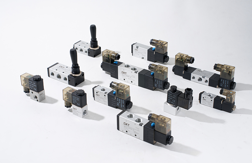
Actuator cylinders fall into two broad mechanical families: single-acting cylinders, which use air pressure to move in one direction and a spring to return, and double-acting cylinders, which use air pressure for both extension and retraction. Double-acting designs account for roughly 75% of industrial pneumatic cylinder installations according to component distributor data from Festo and SMC catalogs, largely because they offer controlled force and speed in both directions and don't waste energy compressing a return spring on every cycle.
Calculating Cylinder Force: The Numbers That Matter
The force formula for a pneumatic cylinder is straightforward: Force (N) = Pressure (bar) x Area (cm²) x 10. The piston area is calculated from the bore diameter using the standard circle area formula, π times radius squared. For the rod-side (retraction) stroke, the rod's cross-sectional area must be subtracted from the total piston area, which is why retraction force is always lower than extension force on a double-acting cylinder, often by 10% to 15% depending on rod diameter.
| Bore Diameter | Piston Area | Force at 6 Bar | Typical Application |
|---|---|---|---|
| 16 mm | 2.01 cm² | 120 N | Small part ejection, gating |
| 25 mm | 4.91 cm² | 295 N | Light clamping fixtures |
| 32 mm | 8.04 cm² | 482 N | Conveyor stops, push plates |
| 50 mm | 19.63 cm² | 1178 N | Press fitting, sheet metal forming |
| 80 mm | 50.27 cm² | 3016 N | Heavy clamping, die casting tooling |
It's worth noting that the theoretical force from this formula represents the maximum available output before friction losses. Real-world delivered force runs about 5% to 10% lower due to seal friction, particularly in cylinders that have been running for extended periods without lubrication maintenance.
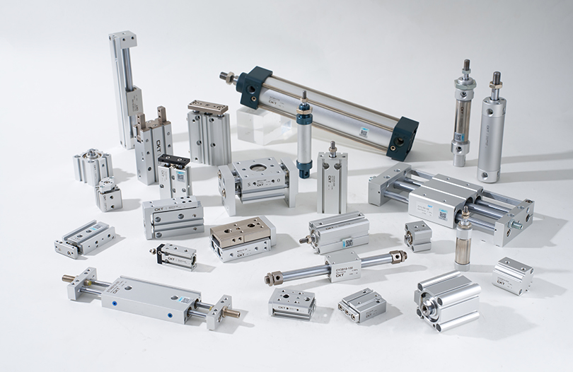
Cylinder Body Styles and When Each One Fits
Air cylinders are manufactured in several body configurations, and picking the wrong style is one of the most common sources of premature wear on automated equipment.
Round Body (ISO 6432) Cylinders
These are the most compact option for a given bore size and mount easily into tight machine frames using clevis or flange brackets. They're commonly found in bore sizes from 8mm to 25mm and are favored for pick-and-place arms, small ejector mechanisms, and gating applications where space along the actuation axis is limited.
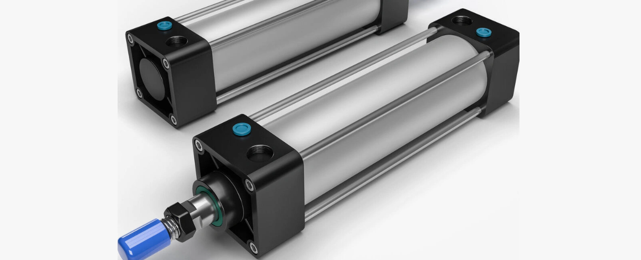
Profile Body (ISO 15552) Cylinders
Square or rectangular cross-section bodies with integrated mounting slots along all four sides. The flat surfaces and T-slot grooves let designers bolt sensors, brackets, and guide rails directly to the cylinder body without extra fixtures. This style dominates in the 32mm to 125mm bore range and is the default choice for general industrial automation.
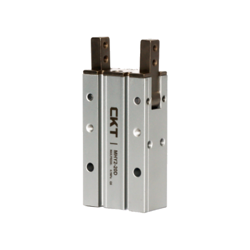
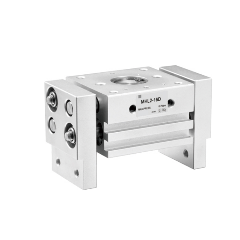
Guided (Slide) Cylinders
These combine a standard cylinder with built-in linear guide rods, typically two hardened steel shafts running parallel to the main rod. The guide rods absorb side loads and torque that would otherwise bend or wear out a standard cylinder rod and seal. Any application where the load is applied off-center from the rod's centerline, such as a pusher arm or a rotating gripper, should use a guided cylinder rather than a standard rod cylinder, because side loading is the single biggest cause of premature rod seal failure.
Compact Cylinders
Short stroke, flat profile units designed for clamping operations where axial space is at a premium, such as on multi-station rotary tables. Stroke lengths rarely exceed 50mm, but the flat mounting face and reduced overall length make them ideal for installations where a standard cylinder simply won't fit.
Mounting Styles and Their Mechanical Trade-offs
The mounting style chosen affects not just installation but the bending stress the cylinder body and rod experience during operation.
- Foot mounting: Bolted along the bottom of the cylinder body, simple and rigid, but requires the load path to be perfectly aligned to avoid bending moments on the body tube.
- Flange mounting: Bolted at the cap or head end, very rigid for axial push/pull applications, common on press and stamping equipment.
- Trunnion mounting: A pivot point allows the cylinder to swing as it extends, essential for clamp arms and lift mechanisms that rotate through an arc rather than moving in a straight line.
- Clevis mounting: A pin-and-fork connection at the rear of the cylinder, frequently paired with a clevis at the rod end as well, allowing the entire cylinder to pivot during the stroke.
Trunnion and clevis mounts are the only choices that should be used when the actuation path is not a straight line, since rigid mounts on a pivoting load will quickly bend the piston rod.
Air Consumption: Sizing the Compressor Correctly
One overlooked factor when adding cylinders to an existing pneumatic system is total air demand. Each cycle of a cylinder consumes a volume of compressed air equal to the piston area multiplied by the stroke length, doubled for double-acting cylinders since both chambers fill and exhaust each cycle.
For example, a 50mm bore cylinder with a 200mm stroke has a piston volume of roughly 393 cm³ on the extension side. Add the rod-side volume (slightly less due to rod displacement, call it 370 cm³), and one full cycle consumes about 763 cm³ of free air at atmospheric pressure, multiplied by the compression ratio. At 6 bar (7 bar absolute), that's roughly 5.3 liters of free air per cycle. A machine running this cylinder at 20 cycles per minute will consume approximately 106 liters per minute of free air just for that one actuator, which is a meaningful load when multiplied across a machine with a dozen or more cylinders.
| Bore Size | Stroke 100mm | Stroke 200mm | Stroke 300mm |
|---|---|---|---|
| 25 mm | 26 L/min | 52 L/min | 78 L/min |
| 32 mm | 42 L/min | 84 L/min | 127 L/min |
| 50 mm | 53 L/min | 106 L/min | 159 L/min |
| 80 mm | 135 L/min | 271 L/min | 406 L/min |
Plants commonly underestimate compressor sizing when adding new automation cells because they calculate based on cylinder bore alone without factoring in cycle rate. A compressor that is undersized for total demand causes line pressure to sag during peak cycling, which directly reduces the force output of every cylinder on the system simultaneously, sometimes leading technicians to misdiagnose the symptom as a failing actuator when the real cause is upstream.
End-of-Stroke Cushioning and Why It Extends Service Life
At the end of each stroke, the piston decelerates by slamming into the end cap unless some form of cushioning is present. Standard cylinders without cushions are limited to relatively low piston velocities, generally under 0.3 meters per second, before impact forces start damaging the piston, end caps, and mounting hardware.
Adjustable cushioning uses a needle valve to throttle the exhaust air in the final 10 to 15mm of travel, slowing the piston before it contacts the end cap. This single feature can extend cylinder service life significantly, because the repeated mechanical shock of an uncushioned stop is a major contributor to seal wear, fastener loosening, and eventual cracking of the end cap casting on aluminum-bodied cylinders.
For applications running above 0.5 m/s, or for any cylinder carrying a load mass above a few kilograms, adjustable air cushioning should be considered a standard requirement rather than an optional upgrade. Rubber bumpers offer a lower-cost alternative for lighter loads and lower speeds, absorbing impact through elastic deformation rather than air throttling, but they wear out and require periodic replacement.
Material Selection for Different Operating Environments
The body, rod, and seal materials of an actuator cylinder determine how well it survives outside a clean, dry, climate-controlled factory floor.
Standard Aluminum Body Cylinders
Anodized aluminum is the default for general indoor use. It's lightweight, resists surface corrosion from normal humidity, and machines easily for the precision bores required to maintain a good seal. It is not suitable for environments with caustic washdown chemicals or constant saltwater exposure without additional coatings.
Stainless Steel Cylinders
Used in food processing, pharmaceutical, and marine applications where washdown with chlorinated cleaners or exposure to salt air is routine. Stainless cylinders cost more, typically 1.5 to 2.5 times the price of an equivalent aluminum unit, but avoid the pitting corrosion that would otherwise require frequent replacement in these environments.
Seal Compounds
Nitrile (NBR) seals are standard for general air service at temperatures from -20°C to 80°C. For high-temperature applications near ovens or welding stations, fluorocarbon (FKM/Viton) seals extend the usable range up to around 150°C but cost considerably more. For food-grade and pharmaceutical machinery, FDA-compliant seal compounds are required and should be specified explicitly when ordering, since standard seals may not meet sanitary processing requirements.
Common Failure Symptoms and Their Root Causes
Field technicians repeatedly encounter the same handful of failure patterns on actuator cylinders, and recognizing them quickly saves significant downtime.
| Symptom | Likely Cause | Corrective Action |
|---|---|---|
| Slow or sluggish stroke | Undersized tubing, restrictive fittings, or low line pressure | Check supply pressure at the cylinder port, upsize tubing diameter |
| Air leaking from rod end | Worn rod seal, often from side loading or contamination | Replace seal kit, inspect for rod scoring and side load source |
| Cylinder drifts when air is off | Internal piston seal bypass allowing air transfer between chambers | Replace piston seal, inspect bore for scoring |
| Loud bang at end of stroke | Missing or worn cushioning, excessive velocity | Adjust cushion needle valve or add flow control on exhaust |
| Bent piston rod | Side loading beyond rated limits, misalignment | Replace with guided cylinder or correct mechanical alignment |
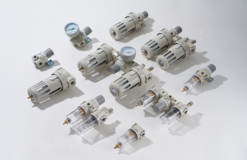
Most premature cylinder failures trace back to two root causes: side loading on the rod from misaligned mounting, and contaminated air supply carrying moisture or particulates into the seals. A properly maintained filter-regulator-lubricator (FRL) unit upstream of each actuator addresses the second cause directly, and routine alignment checks during preventive maintenance address the first.
A Practical Checklist for Specifying a New Actuator Cylinder
When specifying a new pneumatic actuator cylinder for a machine design or retrofit, working through the following points in order avoids the most common specification mistakes.
- Calculate the required force at the lowest expected line pressure, not the nominal pressure, since pressure can sag during peak demand.
- Select bore size with a safety margin of at least 25% above the calculated minimum force requirement.
- Confirm stroke length accounts for full mechanical travel plus any cushioning distance at each end.
- Choose a guided cylinder if any side load or torque will be applied to the rod during the stroke.
- Match seal material and body material to the ambient environment, including temperature, moisture, and chemical exposure.
- Specify cushioning type based on expected piston velocity and load mass.
- Confirm mounting style matches the load path, straight-line versus pivoting motion.
- Add the new cylinder's air consumption to the total system demand and verify compressor capacity.
Following this sequence in order, rather than starting from a catalog part number and working backward, is the difference between an actuator that runs reliably for years and one that becomes a recurring maintenance item within months of installation.


