


Content
- 1 What Is a Pneumatic System and How Does It Work
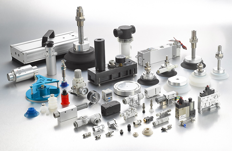
- 2 Core Components of Pneumatic Systems Explained
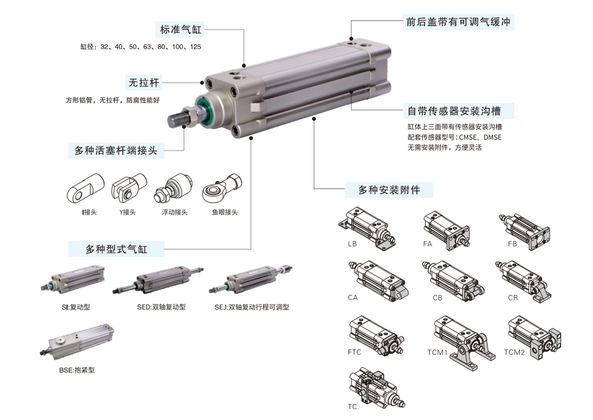
- 3 Air Cylinder Types and Selection Criteria
- 4 How Pressure Regulation Affects Entire Pneumatic System Performance
- 5 Compressed Air Quality Standards and Why They Matter for Cylinders
- 6 Sizing an Air Cylinder Correctly: Bore, Stroke, and Speed Calculations
- 7 Pneumatic System Maintenance: What Breaks First and Why
- 8 Energy Efficiency Strategies for Compressed Air and Pneumatic Systems
- 9 Pneumatic Systems vs. Hydraulic Systems: When to Choose Each
- 10 High-Force Pneumatic Applications and How Air Cylinders Scale Up
- 11 Choosing Air Cylinders for Specific Industry Environments
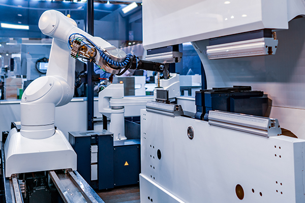
Pneumatic systems are the backbone of modern industrial automation — and understanding how they work, where they fail, and how to optimize them can directly cut downtime and operating costs. This guide covers everything from core components to performance benchmarks, with real figures from production environments.
Core Components of Pneumatic Systems Explained
Compressors
Rotary screw compressors dominate industrial plants because they deliver continuous airflow at consistent pressure. A typical 55 kW rotary screw unit can generate roughly 9–10 m³/min of free air at 7 bar, enough to power dozens of mid-size cylinders simultaneously. Reciprocating piston compressors are common for smaller shops and intermittent-use applications.
Air Receivers
Storage tanks buffer demand spikes and allow the compressor to cycle off during low-load periods. The rule of thumb is 6–10 liters of receiver capacity per m³/min of compressor output. An undersized receiver forces the compressor to short-cycle, increasing wear and energy consumption by up to 20%.
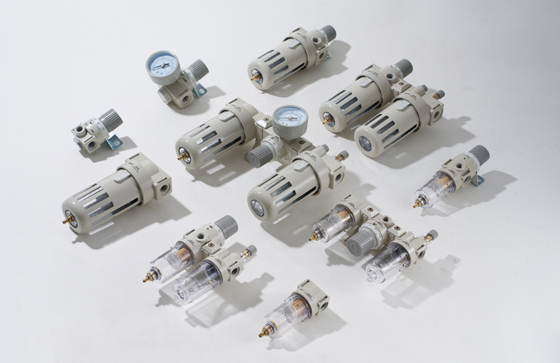
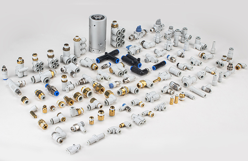
FRL Units
The filter-regulator-lubricator combination is the last line of air preparation before each machine or actuator group. ISO 8573-1 Class 1 filtration targets particles down to 0.01 micron, dew points of -70°C, and oil content below 0.01 mg/m³ — essential for protecting precision air cylinders and valves from contamination-related failures.
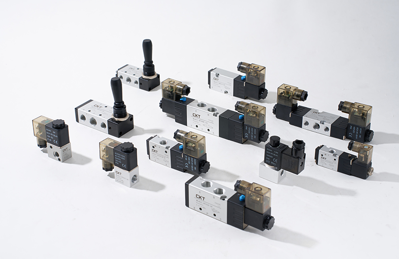
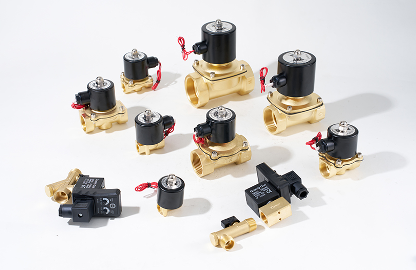
Directional Control Valves
These valves route compressed air to either end of an air cylinder or to an exhaust port. A standard 5/2-way solenoid valve can switch flow paths in under 20 milliseconds, enabling cycle rates above 10 strokes per second in high-speed applications. Valve sizing is critical: an undersized valve creates a pressure drop that limits actuator speed and force.
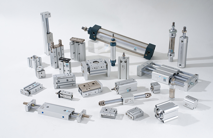
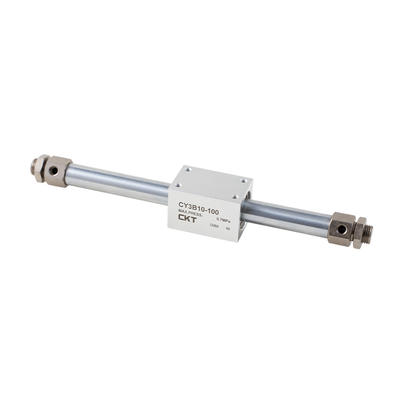
Air Cylinder Types and Selection Criteria
The air cylinder is the workhorse of any pneumatic system, yet it comes in enough variants that selecting the wrong type causes persistent performance or maintenance problems. The table below compares the most common types used in production environments.
| Cylinder Type | Bore Range | Stroke Length | Typical Use | Force Output at 6 bar |
|---|---|---|---|---|
| ISO Standard (Double-Acting) | 12–320 mm | Up to 2,000 mm | General automation, clamping | 68 N – 483 kN |
| Compact / Short-Stroke | 12–100 mm | 1–50 mm | Tight spaces, pressing | 68 N – 47 kN |
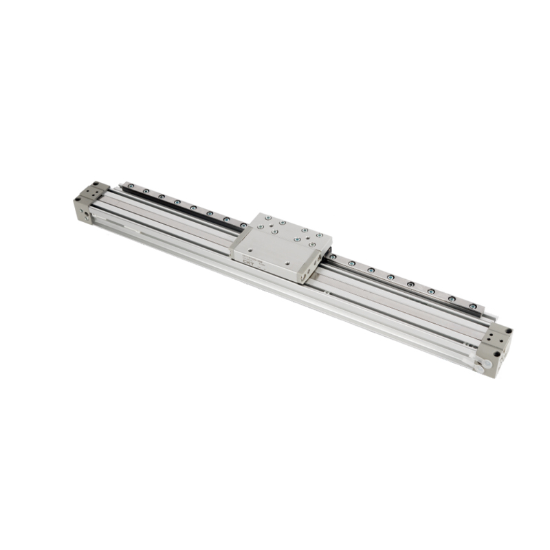
| Rodless Cylinder | 16–80 mm | Up to 10,000 mm | Long-travel transport | 120 N – 30 kN |
| Single-Acting (Spring Return) | 6–125 mm | Up to 200 mm | Fail-safe clamping, valves | 28 N – 73 kN (net) |
| Guided / Slide Cylinder | 16–100 mm | Up to 300 mm | Lateral load applications | 120 N – 47 kN |
| Rotary Actuator | 10–200 mm vane | 90°–270° rotation | Indexing, turning | 0.3–500 Nm torque |
When selecting a cylinder bore size, always add a 25–30% safety margin over the theoretical force requirement to account for friction, pressure drops in the circuit, and seal wear over time. For a load requiring 500 N, choose a bore that delivers at least 650 N at the system's regulated pressure.
Stroke length selection also matters beyond just fitting the required travel. Long strokes increase the risk of rod buckling under compressive loads. Use Euler's buckling formula or the manufacturer's load charts for any stroke exceeding roughly 300 mm — many engineers ignore this until a rod bends and damages tooling or the machine frame.
How Pressure Regulation Affects Entire Pneumatic System Performance
Many facilities run their entire plant distribution at 8 or 10 bar when the majority of actuators only need 5–6 bar. This single habit wastes enormous amounts of energy. For every 1 bar reduction in system pressure, compressor energy consumption drops by approximately 6–8%. In a plant spending $150,000 per year on compressed air energy, dropping from 8 to 6 bar on non-critical circuits can save $18,000–$24,000 annually.
The solution is zone regulation — using dedicated pressure regulators at each machine or machine group to supply only the pressure each actuator needs, while the main distribution runs at a slightly higher header pressure for standby margin. A properly zoned plant typically reduces average network pressure by 1–2 bar without any loss of production throughput.
Pressure Drop: The Silent Performance Thief
Pressure drop between the receiver outlet and the air cylinder port is where most pneumatic system performance problems originate. Every meter of undersized pipe, every sharp 90-degree elbow, every dirty filter element adds resistance. The industry target is to limit total pressure drop from compressor outlet to actuator to no more than 0.5–1.0 bar in a well-maintained system.
Common culprits behind excessive pressure drop:
- Filter elements clogged with rust, scale, or compressor oil — differential pressure across a saturated filter can exceed 0.8 bar alone
- Undersized main distribution pipes — air velocity above 6–8 m/s in mains causes turbulent flow and significant pressure loss
- Quick-connect fittings with internal orifices smaller than the tubing bore
- Directional control valves undersized for the required flow rate (Cv value mismatch)
- Leaks — a 1 mm diameter leak at 7 bar wastes approximately 1.1 m³/min of free air per hour, enough to run several standard air cylinders continuously
Running a pressure survey across the distribution network — recording pressure at the receiver, at each machine inlet manifold, and at the cylinder port under load — reveals exactly where losses are occurring. This takes less than a day and consistently identifies corrective actions that pay back within one quarter.
Compressed Air Quality Standards and Why They Matter for Cylinders
The ISO 8573-1 standard defines compressed air quality classes across three contaminants: solid particles, water (dew point), and total oil. Most industrial applications fall into quality class 3 or 4 for general pneumatics, but precision air cylinders in electronics assembly, food processing, or medical device manufacturing need class 1 or 2 air.
| Quality Class | Max Particle Size | Pressure Dew Point | Max Oil Content | Typical Application |
|---|---|---|---|---|
| Class 1 | 0.1 micron | -70°C | 0.01 mg/m³ | Medical, semiconductor |
| Class 2 | 1 micron | -40°C | 0.1 mg/m³ | Food, pharma packaging |
| Class 3 | 5 micron | -20°C | 1 mg/m³ | General manufacturing |
| Class 4 | 15 micron | +3°C | 5 mg/m³ | Heavy industry, outdoor |
| Class 5 | 40 micron | +7°C | 25 mg/m³ | Pneumatic tools, blowing |
Running class 4 or 5 air through precision air cylinders rated for class 2 or 3 service accelerates seal degradation rapidly. Moisture contamination is particularly aggressive: condensed water inside an air cylinder barrel causes rust, scoring of the bore surface, and eventual seal failure. Studies on industrial actuator failure modes consistently attribute 40–60% of premature failures to contaminated air supply rather than mechanical overload or end-of-life wear.
Refrigerated dryers are the standard solution for class 3 and 4 applications. They chill the compressed air stream to approximately 3°C, causing moisture to condense and drain away. Desiccant dryers achieve the sub-zero dew points required for class 1 and 2 applications but consume more energy — typically 15–20% of compressor power for a heated regenerative unit.
Sizing an Air Cylinder Correctly: Bore, Stroke, and Speed Calculations
Getting the bore size wrong is one of the most common and expensive design errors in pneumatic system engineering. An oversized cylinder wastes compressed air and creates excessive cushioning challenges; an undersized one stalls under load or operates near its seal pressure limits.
Force Calculation
The theoretical output force of a double-acting air cylinder on the extend stroke is:
F = P × A = P × (π × D² / 4)
Where F is force in Newtons, P is supply pressure in Pa, and D is bore diameter in meters. For a 63 mm bore cylinder at 6 bar (600,000 Pa):
F = 600,000 × (3.14159 × 0.063² / 4) = 600,000 × 0.003117 = 1,870 N (approximately 190 kgf)
On the retract stroke, the rod displaces some bore area, reducing force. A 63 mm bore with a 20 mm rod delivers roughly 1,680 N on retraction at the same pressure — a 10% reduction that must be factored into two-direction applications.
Speed and Flow Rate
Cylinder speed depends on the volume of air delivered per unit time. Actuator speed is calculated from:
Q = A × v × (P_abs / P_atm)
Where Q is free air flow in m³/s, A is piston area, v is desired piston velocity in m/s, and P_abs is absolute working pressure. To achieve 0.5 m/s with a 63 mm bore at 6 bar absolute, the valve and tubing must pass approximately 23 liters/min of free air — a useful benchmark for valve Cv selection.
Cushioning Requirements
At speeds above 0.2 m/s, pneumatic cylinders require end-of-stroke cushioning to prevent hard impact damage to the piston, rod, and connected tooling. Built-in adjustable cushions work for moderate speeds up to about 0.5 m/s. Above that, external hydraulic shock absorbers or programmable deceleration via proportional valves are necessary. Ignoring cushioning on a 100 mm bore cylinder traveling at 1 m/s can generate impact forces exceeding 3–5 kN on the end cap — far beyond what most mounting hardware tolerates over thousands of cycles.
Energy Efficiency Strategies for Compressed Air and Pneumatic Systems
Compressed air is often called "the fourth utility" in manufacturing — and it is consistently the most expensive one on a per-unit-of-work basis. Electricity-to-mechanical-work conversion efficiency for a compressed air system is typically only 10–15% at the actuator, compared to 85–90% for direct electric motor drives. This makes energy optimization critically important.
Step 1
Measure Actual Air Consumption
Install flow meters at the main compressor outlet and at each major machine group. Most plants discover that 20–30% of machines use disproportionately large amounts of air relative to their production output. These become the priority targets for cylinder resizing, pressure reduction, or process redesign.
Step 2
Reduce and Right-Size Working Pressure
Audit every machine and air cylinder for its actual pressure requirement. Replace oversized cylinders with correctly sized ones at lower pressure. Install point-of-use regulators set to the minimum required pressure. In facilities with diverse pressure requirements, consider splitting into high-pressure and low-pressure distribution rings rather than supplying everything at peak demand pressure.
Step 3
Recover Compressor Heat
Rotary screw compressors reject approximately 80–90% of their input energy as heat in the compression process. Installing a heat recovery system on the compressor cooling circuit captures this thermal energy for space heating, process water heating, or drying applications. Payback periods for heat recovery are typically 1–3 years.
Step 4
Replace Constant-Speed Compressors with Variable Speed Drives
A variable speed drive (VSD) compressor modulates its motor speed to match actual air demand in real time, rather than loading and unloading at full speed. In plants with fluctuating demand, VSD compressors save 20–35% of compressor energy compared to fixed-speed units. The break-even point is typically when system utilization falls below 80% of rated capacity for significant portions of the shift.
Step 5
Implement a Leak Detection and Repair Program
Ultrasonic leak detectors can identify leaks through background noise at distances up to 10 meters. A structured program — tagging leaks, quantifying their flow rate, prioritizing by cost, and tracking repair completion — consistently achieves leak reduction from a typical 20–30% loss rate to below 5–8% within 12 months. This alone often eliminates the need for additional compressor capacity.
Pneumatic Systems vs. Hydraulic Systems: When to Choose Each
Both pneumatic and hydraulic systems deliver force through a fluid medium, but their characteristics make each better suited to specific applications. Confusing the two leads to overengineered, expensive systems or underperforming ones.
Characteristic
Pneumatic System
Hydraulic System
Working pressure
4–10 bar typical
100–700 bar typical
Force output
Up to ~50 kN practical
Up to several MN
Speed
Fast; up to 3 m/s common
Moderate; 0.1–0.5 m/s typical
Position control
Difficult (air compressibility)
Excellent (incompressible fluid)
Contamination risk
Low (air exhausted)
High (oil leaks, disposal)
Maintenance complexity
Lower; standard skills
Higher; fluid analysis needed
Installation cost
Lower
Higher (reservoir, filtration, seals)
Best use case
High-speed, light-to-medium force, clean environments
High force, precise positioning, heavy industry
A practical boundary: where force requirements exceed roughly 50 kN or where precise mid-stroke position holding is mandatory, hydraulics are usually the better choice. Below that threshold, pneumatic systems win on speed, simplicity, cleanliness, and lower total system cost. In many hybrid applications — such as pneumatically operated clamps on a hydraulic press — both technologies coexist on the same machine.
High-Force Pneumatic Applications and How Air Cylinders Scale Up
When standard air cylinder bore sizes cannot deliver the required force at available system pressure, several design strategies extend pneumatic capability before switching to hydraulics becomes necessary.
Tandem Cylinders
Two air cylinder units mounted coaxially with their rods linked multiply output force without increasing bore size. A tandem pair of 100 mm bore cylinders at 6 bar delivers approximately 9.4 kN — nearly double the single-unit output — while maintaining the same cylinder diameter for tight space envelopes. The tradeoff is increased overall length and proportionally higher air consumption.
Air-over-Oil Intensifiers
These hybrid devices use a large-bore pneumatic piston driving a small-bore hydraulic piston to achieve hydraulic pressure from a pneumatic supply. A 10:1 intensifier fed at 7 bar produces 70 bar of hydraulic output, suitable for pressing, clinching, or staking operations that need precise force with clean exhaust. Air-over-oil systems eliminate the need for a full hydraulic power unit while achieving press forces of 50–200 kN in compact bench-mount configurations.
Pneumatic Cylinder Multipliers via Mechanical Linkage
Toggle mechanisms, cam followers, and lever linkages mechanically amplify air cylinder output at the point of application. A simple toggle clamp driven by a 50 mm bore cylinder at 6 bar can develop clamping forces exceeding 20 kN at the end of travel when the toggle geometry approaches dead-center. This technique is widely used in welding fixtures and press tools.
Larger Bore Standard Cylinders
ISO 15552-compliant cylinders are available in bore sizes up to 320 mm. At 6 bar, a 320 mm bore air cylinder delivers approximately 483 kN of theoretical thrust — approaching small hydraulic cylinder territory. These large-bore units consume substantial air volumes per stroke (a 300 mm stroke on a 320 mm bore displaces approximately 24 liters of free air per cycle), so receiver sizing and compressor capacity must be carefully reviewed before specifying them.
Choosing Air Cylinders for Specific Industry Environments
Not all air cylinder bodies and seal materials suit every operating environment. Specifying the wrong variant for harsh or specialized conditions causes accelerated failure regardless of how well the rest of the pneumatic system is designed.
- Food and beverage: Stainless steel body cylinders with FDA-compliant seal materials (silicone or EPDM), no external lubrication, and smooth outer profiles that resist bacterial buildup. Washdown-rated (IP67 or IP69K) variants tolerate high-pressure water and chemical cleaning cycles.
- High-temperature environments: Standard NBR seals fail above 80°C. For foundry, ovens, or near-process applications above 100°C, specify fluoroelastomer (FKM/Viton) seals rated to 200°C. Above 150°C ambient, external heat shields on the cylinder body are also needed to protect retaining rings and end caps.
- Corrosive atmospheres: Electroless nickel-plated or hard-anodized aluminum bodies resist mild chemical exposure. In marine, offshore, or chemical plant environments, fully stainless steel construction with PTFE-lined bores offers the best corrosion resistance at the cost of higher weight and price.
- ATEX/explosion-proof zones: Pneumatic actuators are inherently safer than electric drives in hazardous zones because they produce no sparks. However, valve solenoids and position sensors attached to the air cylinder must carry appropriate ATEX zone ratings. The cylinder body itself needs to be verified non-sparking — aluminum is generally acceptable, but cast iron should be checked against zone classification requirements.
- Cleanroom applications: ISO Class 5 and better cleanrooms require cylinders with outgassing-free seals, no external lubrication, and vacuum-compatible materials. Some semiconductor and flat panel display manufacturers use entirely plastic-bodied cylinders to eliminate any risk of metallic contamination.
- Outdoor and construction equipment: Cylinders exposed to weather need zinc-nickel or hard chrome rod coatings, heavy-duty wiper seals to exclude dirt, and anodized or painted bodies. Pressure specifications should account for temperature extremes: at -30°C, standard lubricants thicken and seal materials stiffen, requiring low-temperature grease and cold-rated elastomers.
Matching the air cylinder specification to the actual operating environment — rather than defaulting to a general-purpose catalog selection — is where experienced pneumatic system engineers add measurable value. The incremental cost of the correct variant is almost always less than one unplanned replacement cycle after an early field failure.
Pneumatic systems, at their core, are reliable, fast, and cost-effective when designed with the right component specifications, proper air quality, correct sizing, and a structured maintenance approach. The air cylinder remains the most visible element, but its performance is entirely dependent on the quality of the compressed air system feeding it. Invest in air preparation and pressure management, and the actuators downstream will deliver the cycle life their design intends.


