


Content
- 1 What Is a Double Action Cylinder and Why It Dominates Industrial Automation
- 2 How a Double Action Air Cylinder Works: The Full Stroke Sequence
- 3 Key Components of a Double Action Cylinder
- 4 Force and Speed Calculations for Double Action Air Cylinders
- 5 Types of Double Action Cylinders: Choosing the Right Variant
- 6 Double Action Cylinder vs Single Acting Cylinder: A Practical Comparison
- 7 Industrial Applications of Double Action Air Cylinders
- 8 How to Select the Right Double Action Cylinder for Your Application
- 9 Maintenance Best Practices for Double Action Air Cylinders
- 10 Common Problems with Double Action Cylinders and How to Fix Them
- 11 Double Action Cylinder Standards and Specifications to Know
What Is a Double Action Cylinder and Why It Dominates Industrial Automation
A double action cylinder — also called a double-acting air cylinder — is a pneumatic or hydraulic actuator that uses pressurized fluid or compressed air to drive the piston in both the extension and retraction directions. Unlike a single-acting design that relies on a spring or gravity to return the piston, a double action cylinder delivers powered, controlled force for both strokes. This makes it the dominant actuator choice in manufacturing, packaging, robotics, and automation worldwide.
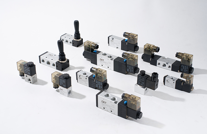
The core operating principle is straightforward: two ports sit at opposing ends of the cylinder barrel. When compressed air enters Port A, it pushes the piston forward (extension stroke), while air exhausts through Port B. To retract, the air supply switches — compressed air enters Port B, driving the piston backward, and air exits through Port A. A directional control valve, typically a 5/2 or 4/2 solenoid valve, switches these airflow paths on command. The result is a smooth, repeatable, bidirectional linear motion that a spring-return cylinder simply cannot match in speed, precision, or consistency.
Double-acting air cylinders account for the majority of pneumatic actuators installed on modern production lines, and once you understand the mechanics behind them, the reason becomes obvious. This guide covers everything engineers and maintenance teams need: working principles, component anatomy, force calculations, key variants, comparative data against single-acting cylinders, selection criteria, and maintenance best practices.
How a Double Action Air Cylinder Works: The Full Stroke Sequence
Understanding the stroke sequence of a double action air cylinder is essential before specifying one for any application. The operating cycle has four recognizable stages that repeat for every work cycle.
Stage 1 — Rest Position
At rest, the piston sits inside the cylinder barrel with the rod fully retracted. Both ports are closed or vented to atmosphere depending on the valve configuration. No air pressure acts on either side of the piston. Seals on the piston and rod prevent air leakage when the system is pressurized in either direction.
Stage 2 — Extension Stroke
Compressed air enters through the rear chamber port (cap end / Port A). The air pressure acts across the full bore area of the piston, generating an outward thrust force. The rod-side chamber simultaneously exhausts through Port B. The piston and rod advance until the rod reaches full stroke or contacts a mechanical stop. This is the working stroke in most applications — pushing, clamping, pressing, or positioning a load.
Stage 3 — Full Extension Hold
At full extension, supply pressure is maintained to keep the piston at position. Cushioning devices — air cushions built into the end caps — bleed off residual air to decelerate the piston just before it hits the end cap, dramatically reducing impact and extending cylinder service life. End-of-stroke sensors or proximity switches (magnetic piston types) signal the control system that the cylinder has reached position.
Stage 4 — Retraction Stroke
The directional valve switches, connecting compressed air to Port B (rod end) and exhausting Port A. Because the rod occupies a portion of the bore area on the rod side, the effective force area is smaller — meaning retraction force is slightly less than extension force at the same supply pressure. However, retraction speed is actually faster than extension speed for the same reason: the same volumetric flow of air fills a smaller chamber, so the piston moves more quickly. After the retraction stroke, the cylinder returns to Stage 1 and the cycle repeats.
This simple four-stage sequence is what makes a double action cylinder so powerful in high-cycle applications. There is no dependence on a spring — whose force degrades with fatigue — and no reliance on gravity or external load to return the piston. The control system dictates every movement with precision.
Key Components of a Double Action Cylinder
A double action air cylinder may appear deceptively simple from the outside, but its performance depends on each internal component working correctly. Here is a breakdown of the critical parts:
Cylinder Barrel (Tube)
The barrel is the main body of the cylinder. It is most commonly made from aluminum alloy (common in pneumatic cylinders for weight savings), stainless steel (for corrosive environments), or carbon steel (for hydraulic cylinders under high pressure). The inner bore surface is precision-honed to a fine finish to minimize friction and ensure seals maintain proper contact throughout the stroke. Bore diameters for standard pneumatic cylinders typically range from 8 mm to 320 mm, with some specialty designs exceeding this range.
Piston
The piston is the sliding element that divides the cylinder into two pressure chambers. It is fitted with piston seals (commonly NBR or polyurethane O-rings and cup seals) that maintain the pressure differential between the two sides while minimizing friction. Many modern double action cylinder pistons include a built-in magnet ring, allowing external magnetic proximity switches to detect piston position without penetrating the cylinder wall — a key feature for automation feedback systems.
Piston Rod
The piston rod transmits the linear force generated by the piston to the external load. Hard chrome plating is the standard surface treatment for pneumatic rods — it provides corrosion resistance and a low-friction surface for the rod seal to run against. Rod diameters are selected based on the compressive and tensile load they must handle without buckling. For long-stroke cylinders, rod diameter is often oversized relative to the piston bore to prevent buckling under side loads.
End Caps (Head and Cap Covers)
Two end caps seal the barrel at each end. The rod-side cap (head cover) contains the rod seal and wiper seal that prevent air leakage along the rod and keep external contaminants out of the cylinder. The cap-side cover (blind end) seals the opposite end. Both end caps contain the inlet/outlet ports. Aluminum die-cast end caps can reduce the overall weight of a double action cylinder by approximately 50% compared to traditional machined steel versions, according to specifications from major ISO cylinder manufacturers.
Seals
Seals are the most maintenance-sensitive components in any air cylinder. A typical double-acting air cylinder uses: piston seals (to contain air between chambers), rod seals (to prevent air escaping along the rod), wiper seals (to scrape contaminants off the rod surface as it retracts), and static O-ring seals at ports and end cap mating faces. Material selection — NBR for general use, FKM (Viton) for high temperature or chemical exposure, PTFE for low friction — significantly affects both performance and service life.
Air Cushion Devices
At the end of each stroke, a cushion spear or sleeve on the piston rod enters a cushion pocket in the end cap, trapping a small volume of air. The trapped air compresses and decelerates the piston before it contacts the end cap. Adjustable needle valves on the end cap allow the cushion bleed rate to be tuned for different loads and speeds. Well-adjusted cushioning can extend cylinder life by an order of magnitude in high-speed, heavy-load applications.
Ports and Fittings
Standard pneumatic cylinders follow ISO 15552 or ISO 6432 (UNITOP/compact series) thread specifications for ports — commonly M5, G 1/8, G 1/4, G 3/8, or G 1/2 depending on bore size and flow requirements. Undersized ports relative to bore size are one of the most common causes of sluggish double action cylinder performance in the field, as they restrict the flow of compressed air in and out of the chambers.
Force and Speed Calculations for Double Action Air Cylinders
Correct sizing of a double action cylinder requires calculating both thrust force and cylinder speed. Getting these numbers right at the design stage prevents oversizing (waste of air and money) and undersizing (cylinder stalls under load or cycles too slowly).
Extension Force
The theoretical extension thrust force of a double action air cylinder is calculated as:
F_extend = P × A_bore = P × (π/4) × D²
Where P is the supply pressure (in Pa or bar), D is the bore diameter (in meters or mm). For a 63 mm bore cylinder operating at 6 bar (0.6 MPa), the theoretical extension force is approximately 1,870 N (about 190 kgf). In practice, a friction deduction factor of 5–10% is applied to arrive at the usable thrust force. Always add a safety margin of at least 25–30% on top of the required load force when selecting bore size.
Retraction Force
The retraction force is always less than the extension force because the piston rod occupies part of the bore area on the rod side:
F_retract = P × (A_bore − A_rod) = P × (π/4) × (D² − d²)
Where d is the rod diameter. For the same 63 mm bore cylinder with a 20 mm rod, retraction force drops to approximately 1,682 N at 6 bar — about 10% less than extension force. This asymmetry must be considered when the retraction stroke must lift or work against a load rather than simply returning freely.
Piston Speed
Cylinder speed is governed by the volumetric airflow into the active chamber. Standard pneumatic double action cylinder operating speeds range from 50 mm/s to 1,000 mm/s, with controlled speeds using flow control valves typically set between 100–500 mm/s for most industrial assembly and clamping applications. Very high-speed applications — such as pneumatic presses in packaging lines — can reach 1.5–2 m/s, which is why proper end cushioning is critical at these velocities.
| Bore Diameter (mm) | Theoretical Extension Force (N) | Usable Force at 90% Efficiency (N) | Typical Rod Diameter (mm) |
|---|---|---|---|
| 25 | 295 | 265 | 10 |
| 40 | 754 | 679 | 16 |
| 63 | 1,870 | 1,683 | 20 |
| 100 | 4,712 | 4,241 | 32 |
| 160 | 12,064 | 10,858 | 50 |
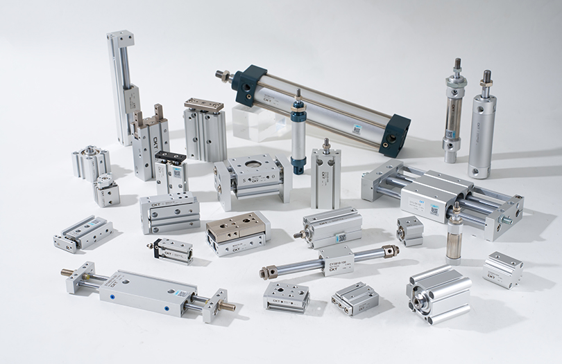
Types of Double Action Cylinders: Choosing the Right Variant
Not all double action cylinders are the same. Several design variants exist to address different motion control requirements, space constraints, and load conditions.
Standard Single-Rod Double-Acting Air Cylinder
This is the most widely used type — a single piston rod extending from one end of the barrel. It is compliant with ISO 15552 (formerly ISO 6431) standards for medium-duty applications, with bore sizes from 32 mm to 320 mm and strokes typically up to 2,000 mm. The asymmetric force characteristic (higher extension force than retraction force) suits most push-and-return applications in assembly lines, clamping fixtures, and conveyor systems.
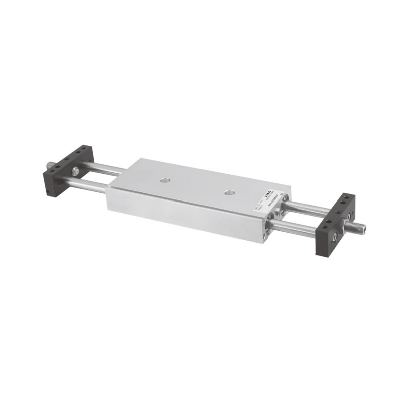
Double-Rod Double-Acting Cylinder
A double-rod double acting cylinder has piston rods extending from both ends of the barrel. Because the rod cross-section area is equal on both sides of the piston, extension and retraction forces are identical. This is important in applications where synchronized equal-force push and pull is required. Double-rod variants are also used when work needs to be done simultaneously at both ends of the stroke — for example, driving two parallel tooling fixtures from a single actuator. Aluminum die-cast end covers on double-rod designs can reduce overall weight by approximately 50% compared to cast iron equivalents at the same bore size.
Compact / Short-Stroke Double-Acting Cylinder (ISO 21287)
Compact cylinders follow ISO 21287 standards. They are designed for tight installation envelopes where a full-length ISO 15552 cylinder would not fit. Bore sizes range from 20 mm to 100 mm with strokes typically from 10 mm to 80 mm. Despite their small footprint, they deliver full double-acting bidirectional control, making them popular in PCB handling equipment, small assembly jigs, and electronics manufacturing automation.
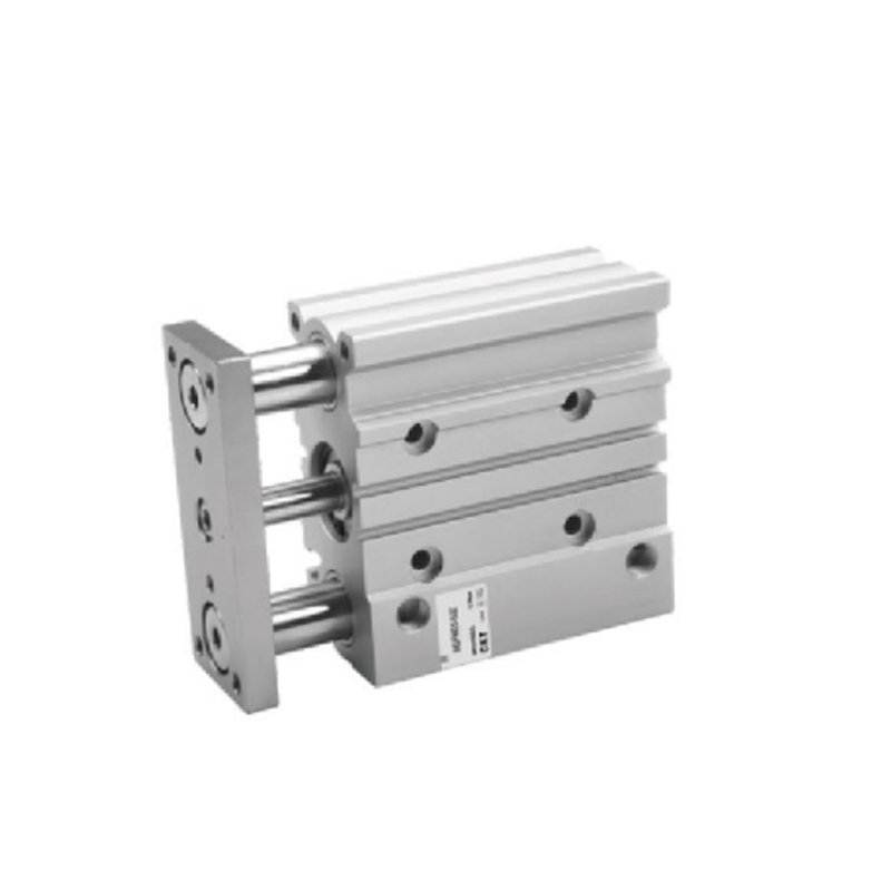
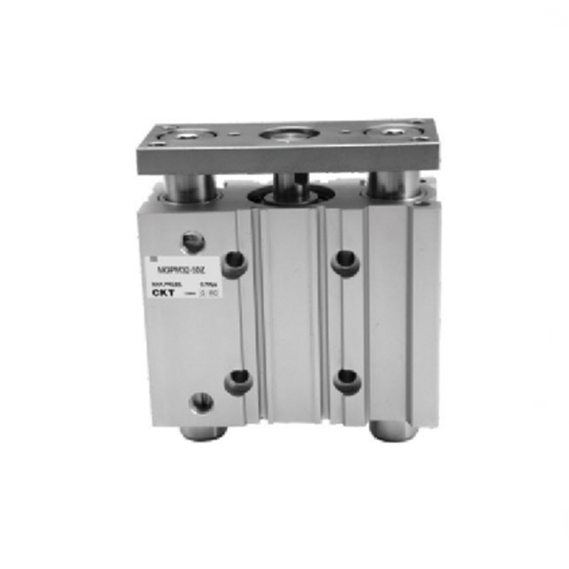
Guided (Dual-Rod) Double-Acting Cylinder
A guided double action air cylinder uses two parallel guide rods connected to a yoke plate at the rod end. This eliminates rod rotation and dramatically reduces side-load deflection compared to a standard single-rod cylinder. When an application involves lateral forces or moment loads — such as a robot gripper arm, a vertical lifting fixture, or a tooling plate that must remain precisely parallel — a guided cylinder prevents the piston from drifting off-axis. Bronze bushings or linear ball bearings in the guide rod housings determine load capacity and service life; bronze bushing designs handle heavier side loads while ball bearing types offer lower friction at high cycle rates.
Rodless Double-Acting Cylinder
In a rodless double acting cylinder, the piston drives an external carriage along the cylinder body rather than pushing a rod out from one end. The absence of a protruding rod means the total installation length equals the stroke length rather than double the stroke length as with a conventional rod cylinder. Magnetically coupled or mechanically coupled rodless cylinders are available, with the coupled type handling significantly higher side loads. Stroke lengths up to 5,000 mm or more are achievable, making rodless double-acting cylinders the standard choice for long-travel material handling, gantry slides, and linear transfer systems.
Rotary Double-Acting Cylinder
Rotary actuators use the double-acting principle to produce angular (rotational) output motion rather than linear motion. Vane-type and rack-and-pinion type rotary double-acting air cylinders can produce 90°, 180°, or 270° rotation in both directions, with torque output controlled by air pressure and vane/piston area. These are widely used in valve actuation, rotary indexing tables, and robotic wrist joints.
Double Action Cylinder vs Single Acting Cylinder: A Practical Comparison
The choice between a double action cylinder and a single-acting cylinder is one of the most common decisions in pneumatic system design. Both use compressed air as the energy source, but their performance characteristics differ significantly across several dimensions.
| Parameter | Double Action Cylinder | Single Acting Cylinder |
|---|---|---|
| Return mechanism | Compressed air | Spring, gravity, or load |
| Number of ports | 2 | 1 |
| Force in both directions | Yes (full air pressure both ways) | No (return force is spring-limited) |
| Cycle speed | Faster (air drives both strokes) | Slower return stroke |
| Stroke length flexibility | High (long strokes feasible) | Limited (spring space reduces usable stroke) |
| Force consistency over life | Consistent (air pressure controlled) | Degrades (spring fatigues over time) |
| Valve complexity | 4/2 or 5/2 directional valve required | Simpler 3/2 valve sufficient |
| Initial cost | Higher (cylinder + more complex valve) | Lower |
| Long-term maintenance cost | Lower (no spring to replace) | Higher (springs require periodic replacement) |
| Best application fit | High-cycle, bidirectional, precision automation | Low-cycle, one-directional simple tasks |
One frequently overlooked point: single-acting cylinders consume less compressed air per cycle because the return stroke uses stored spring energy rather than compressed air. However, the spring's opposing force during extension reduces usable thrust, and as the spring fatigues through tens of thousands of cycles, both return force and precision degrade. A double action cylinder maintains consistent performance regardless of cycle count — making it the more cost-effective solution over a multi-year operational horizon for any application running more than one shift per day.
Industrial Applications of Double Action Air Cylinders
Double action cylinders appear across virtually every sector of modern manufacturing and processing. The following are the highest-volume application areas, along with specific use cases that illustrate why bidirectional air-powered actuation is the preferred solution.
Automated Assembly and Production Lines
On high-speed assembly lines, double-acting air cylinders drive the push-and-pull motion of pick-and-place units, parts feeders, escapements, and transfer slides. Cycle rates of 60 to 120 strokes per minute are common, and the precise, repeatable motion of a double action air cylinder ensures consistent part positioning at every cycle. A single misalignment caused by an inconsistent spring return — as occurs with worn single-acting cylinders — can result in rejected assemblies and costly downtime.
Packaging and Printing Machinery
Box erecting, flap folding, sealing, and roller adjustment in packaging lines all rely on double action cylinders. The bidirectional control allows a single cylinder to both open and close a flap, rather than requiring two separate actuators. In printing machinery, roller gap adjustment cylinders must deliver equal force in both the press and release directions — a requirement that only a double-acting design can consistently meet.
Clamping, Pressing, and Fixture Holding
Machine tool fixtures, welding jigs, and press-fit stations use double-acting air cylinders to apply consistent clamping force and then release the workpiece under positive pneumatic control. A spring-return clamp can fail to release if the spring is weakened or if back-pressure on the rod side prevents the spring from overcoming the load. A double action cylinder applies positive release force from the air supply, eliminating this failure mode entirely.
Conveyor Diverting and Sorting Systems
Diverter gates, pusher arms, and stop/go escapements on conveyor lines must cycle rapidly and predictably in both directions. Double action air cylinders handle these applications at rates that spring-return cylinders cannot reliably sustain. In a sorting system handling, for example, 200 packages per hour, each diverter cylinder might cycle 3–4 times per minute — over 6,000 cycles per day. Consistent performance at these cycle counts requires the durable, non-degrading motion of a double-acting design.
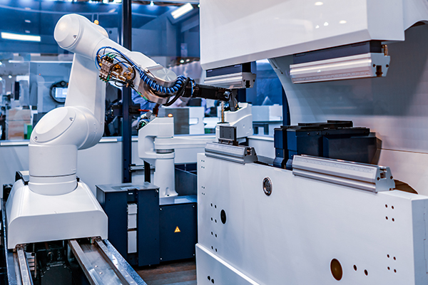
Robotics and End-of-Arm Tooling
Collaborative robots and industrial robot arms frequently use compact double action cylinders in their end-of-arm tooling for gripper open/close functions, tool change mechanisms, and wrist articulation. The lightweight aluminum body of ISO 21287 compact cylinders is critical in robotics, where every gram of end-of-arm mass reduces payload capacity. A 25 mm bore compact double-acting air cylinder can weigh under 100 g while still delivering over 265 N of thrust at 6 bar — an excellent force-to-weight ratio for robotic applications.
Heavy Industry: Earthmoving and Construction Equipment
While pneumatic double action cylinders dominate in light-to-medium industrial automation, hydraulic double-acting cylinders are the backbone of heavy machinery. Excavator boom and bucket arms, bulldozer blades, crane outriggers, and steering systems all depend on hydraulic double-acting cylinders to deliver the massive bidirectional forces required. A hydraulic double action cylinder with a 160 mm bore operating at 250 bar can generate over 500 kN of extension force — far beyond the capability of any pneumatic cylinder at typical industrial air pressures.
How to Select the Right Double Action Cylinder for Your Application
Selecting a double action air cylinder requires working through several parameters systematically. Skipping any of these steps leads to either an undersized cylinder that stalls under load or an oversized one that wastes compressed air and increases cost.
- Define required force: Calculate the load to be moved, including its weight, any friction forces, and any opposing forces such as springs or tooling resistance. Add a 25–30% safety margin to arrive at the minimum required thrust force. Use this value to back-calculate the minimum bore size at your available supply pressure.
- Determine stroke length: Measure the distance the load must travel. Add clearance for any mounting brackets or rod couplings. For strokes longer than approximately 10× the bore diameter, verify that the rod will not buckle under the compressive load using Euler's column buckling formula or the manufacturer's stroke chart.
- Set operating speed: Define the required cycle time. Calculate the minimum air flow rate needed to fill the larger (cap-end) chamber within the available extension time. Size the supply piping, fittings, and flow control valves to deliver this flow rate without creating excessive pressure drop.
- Choose mounting style: ISO standard mounting styles include foot (FA), flange (FB/FF), trunnion (TC/TB), and clevis (CA/CB). The mounting must support the cylinder's weight and reaction forces without inducing bending moments on the rod. Clevis and trunnion mounts allow the cylinder to pivot and are preferred when the load path has angular variation.
- Assess environmental conditions: Standard cylinders with NBR seals operate from −10°C to +80°C. Stainless steel barrel and FKM seal variants cover −20°C to +150°C and resist many chemicals. Wash-down environments require stainless construction and sealed rod end designs to prevent water ingress.
- Verify ISO compliance: For industrial environments where interchangeability and safety standards matter, confirm the double action cylinder meets ISO 15552 (standard), ISO 21287 (compact), or ISO 6432 (miniature) as appropriate. ISO-compliant cylinders from different manufacturers can be swapped without modifying brackets, piping, or control valves.
- Select position sensing method: Magnetic piston cylinders allow externally mounted reed, Hall-effect, or solid-state proximity switches to detect end-of-stroke positions without penetrating the cylinder wall. This is the standard solution for integration with PLCs and automation controllers. Confirm the switch mounting slot type (T-slot, C-slot, or band) matches your preferred sensor.
Maintenance Best Practices for Double Action Air Cylinders
A well-maintained double action cylinder can deliver tens of millions of cycles before requiring seal replacement. The following maintenance practices keep cylinders performing reliably between planned service intervals.
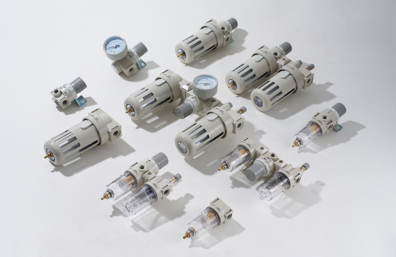
Air Quality: The Most Important Factor
Contaminated compressed air is the primary cause of premature seal wear and cylinder failure. The air supply to any double action air cylinder must be filtered, dried, and in some cases lubricated. A standard FRL unit (Filter-Regulator-Lubricator) installed upstream of each valve island or cylinder bank filters particles to 5–25 microns, reduces moisture, regulates supply pressure to the correct working value (typically 4–8 bar), and adds oil mist lubrication for cylinders that are not specified as non-lubricated. Many modern double-acting air cylinders use pre-lubricated seals and do not require oil mist — check the manufacturer's specification before adding lubrication to a non-lube cylinder, as it can cause seal swelling.
Visual Inspection Intervals
Inspect each double action cylinder every 500,000 cycles or every three months (whichever comes first) for the following signs of wear:
- Air leakage along the piston rod (indicates worn rod seal or damaged wiper seal)
- Air leakage at port fittings (indicates loose fittings or damaged port O-rings)
- Visible scoring or pitting on the exposed rod surface (abrasive contamination in the air supply or damaged wiper)
- Sluggish operation or reduced speed (restricted flow path, excessive back-pressure, or seal friction from swollen seals)
- Excessive end-of-stroke impact noise (cushion needle valves need re-adjustment)
Seal Replacement
Most major manufacturers provide cylinder seal kits containing all seals needed for a full overhaul — piston seals, rod seals, wiper seals, and port O-rings. When replacing seals in a double action cylinder, always replace the complete set rather than individual seals, since uneven seal wear causes differential friction that contributes to alignment issues. Lightly lubricate new seals with clean grease compatible with the seal material before installation. Reassemble end caps to the manufacturer's torque specification to avoid over-compression of static O-rings, which can cause seals to extrude under pressure.
Rod and Barrel Inspection
When the cylinder is disassembled for seal replacement, inspect the rod for surface damage. Minor corrosion pits or score marks deeper than 0.1 mm are sufficient to destroy a new rod seal within a short service period. A rod with surface damage should be re-plated with hard chrome or replaced rather than reassembled with new seals. Similarly, the bore of the cylinder barrel should be inspected for scoring; a bore gauge measurement can quantify wear and determine whether the barrel is within the manufacturer's service limit.
Cushion Adjustment After Service
After any seal replacement or reinstallation of a double action air cylinder, re-adjust the end cushion needle valves with the cylinder running at full operating pressure. Start with the needle valve fully open (minimum cushioning) and gradually close it while observing the end-of-stroke behavior. The correct setting produces a smooth deceleration with no audible impact at either end of the stroke. Over-tightened cushion valves slow cycle time unnecessarily; under-tightened valves allow piston impact that accelerates end cap and seal wear.
Common Problems with Double Action Cylinders and How to Fix Them
Even well-maintained double action air cylinders encounter problems over time. Recognizing these issues early prevents failures from cascading into wider system problems.
Cylinder Fails to Extend or Retract
First check the directional control valve. Confirm the valve is receiving its actuating signal (electrical signal for solenoid valves, pilot air for pneumatic pilot valves). Verify the valve shifts by listening for an audible click or checking flow at the exhaust port. If the valve is functioning but the cylinder does not move, check supply pressure at the cylinder port — a pressure gauge installed at the port quickly identifies whether the issue is upstream (supply loss) or internal to the cylinder (seized piston, damaged seal causing both chambers to equalize pressure).
Cylinder Moves Slowly or Loses Speed Mid-Stroke
Slow operation most commonly results from undersized piping or fittings, a partially closed flow control valve, or contaminated air causing seal swelling and increased friction. Check each potential restriction in order from the compressor outward. A pressure gauge comparison — supply pressure upstream vs. dynamic pressure at the port during motion — reveals whether pressure drop is occurring in the supply circuit. Internal seal friction can be confirmed by disassembling and manually stroking the piston; it should move freely throughout the full stroke with hand pressure alone in a correctly functioning cylinder.
External Air Leakage at the Rod
Leakage past the rod seal is the most common maintenance issue with double action cylinders. The primary causes are rod surface damage (creating a leak path the seal cannot bridge), seal hardening from heat or incompatible oils, and seal extrusion from excessive supply pressure. Confirm the supply pressure is within the cylinder's rated range, inspect the rod surface for damage, and replace the rod seal and wiper seal as a set.
Internal Leakage (Cylinder Drifts Under Load)
If a double action cylinder drifts — that is, the piston moves slowly when the valve is in the hold position — internal leakage across the piston seal is allowing high-pressure air to bypass from the high-pressure chamber to the low-pressure chamber. This is identified by disconnecting the exhaust side of the valve from the cylinder port and feeling for airflow — leaking air will vent from the low-pressure chamber's exhaust path. Replace the piston seal set to correct this condition.
Double Action Cylinder Standards and Specifications to Know
Specifying a double action air cylinder to the correct standard ensures compatibility with existing system components, simplifies replacement sourcing, and confirms minimum safety and performance thresholds.
- ISO 15552 — The primary standard for medium-duty double-acting pneumatic cylinders. Specifies bore sizes (32, 40, 50, 63, 80, 100, 125, 160, 200, 250, 320 mm), mounting dimensions, port thread sizes, and rod end threads. Cylinders from any ISO 15552-compliant manufacturer can be installed interchangeably.
- ISO 21287 — Compact cylinder standard. Covers bore sizes 20–100 mm with short-stroke, space-saving profiles for tight installation envelopes.
- ISO 6432 — Miniature round-body cylinder standard for bore sizes 8–25 mm. Common in electronics assembly and small-scale automation.
- ISO 15552 / CNOMO — Many European automotive plants specify CNOMO (French automobile manufacturer standard) cylinders that are dimensionally identical to ISO 15552 but with additional quality and traceability requirements.
- NFPA T3.6.7 — The US equivalent standard for medium-duty pneumatic cylinders, used extensively in North American industrial applications. Dimensional similarities to ISO 15552 but with some differences in port thread standards (NPT vs. metric).
- Operating pressure range — Standard pneumatic double action cylinders are rated for 1–10 bar (0.1–1.0 MPa). The most common operating range in industrial settings is 4–8 bar. Exceeding the rated pressure accelerates seal wear and risks end cap failure.
- Temperature range — Standard NBR seals operate from −10°C to +80°C. High-temperature FKM seal variants extend the upper limit to +150°C. Low-temperature applications requiring reliable performance below −10°C should specify EPDM or silicone seals.


