
Content
- 1 What Is a Pneumatic Cylinder Double Acting with Magnet?
- 2 How the Double Acting Mechanism Works
- 3 The Role of the Piston Magnet and Position Sensing
- 4 Key Specifications to Understand Before Selecting
- 5 International Standards Governing Double Acting Air Cylinders
- 6 Air Consumption and Energy Efficiency
- 7 Common Industrial Applications
- 8 Comparing Double Acting with Magnet to Other Air Cylinder Types
- 9 Installation Best Practices
- 10 Maintenance Schedule and Troubleshooting
- 11 Choosing Between Major Manufacturers
- 12 Special Variants Worth Knowing
What Is a Pneumatic Cylinder Double Acting with Magnet?
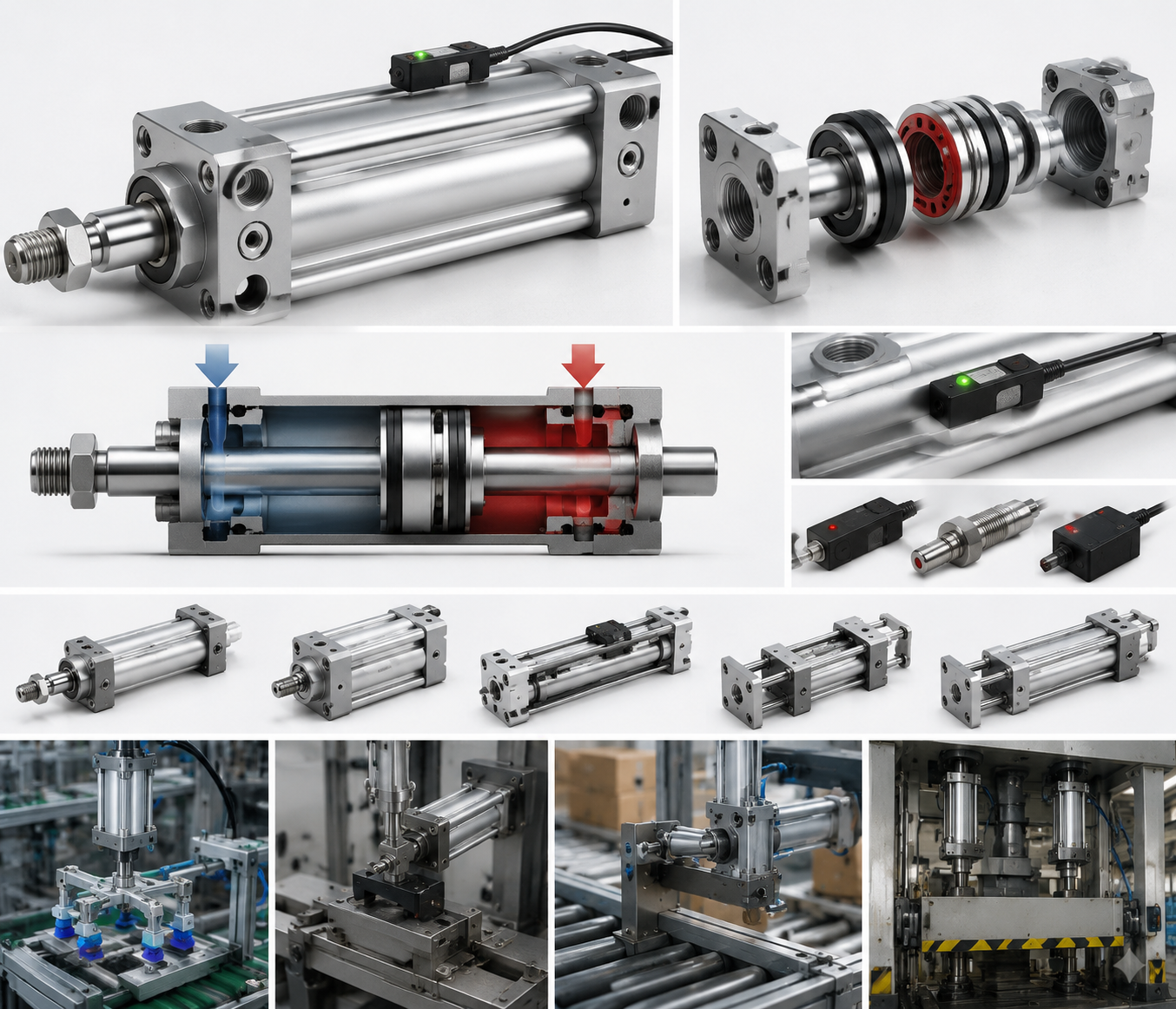
A pneumatic cylinder double acting with magnet is an air cylinder that uses compressed air to drive the piston in both the extend and retract directions, while a permanent magnet embedded in the piston allows an external magnetic reed switch or Hall-effect sensor to detect piston position without any physical contact. This design gives engineers precise, real-time feedback on whether the rod is fully extended, fully retracted, or — with multiple switches — at intermediate positions.
The short answer for anyone selecting an air cylinder for an automated line: if your machine needs positional confirmation before the next step executes, choose a double acting cylinder with a built-in piston magnet. It removes the need for external proximity sensors mounted on brackets, simplifies wiring, and cuts installation time by 30–50% compared to external sensing arrangements.
Double acting cylinders make up the dominant share of pneumatic actuators used in industrial automation — estimates from major component distributors place them at roughly 70–80% of all air cylinder sales — because they deliver controlled force in both directions and allow the machine to push and pull loads actively, rather than relying on a spring return. Adding the magnet feature costs only marginally more but delivers a substantial gain in controllability and diagnostic capability.
How the Double Acting Mechanism Works
The operating principle of a double acting air cylinder is straightforward. Compressed air enters through the rear port and pushes the piston — and the attached rod — forward. When the directional control valve switches, air enters through the front port and drives the piston back. Both the extension stroke and the retraction stroke are powered by air pressure, which is why the term "double acting" is used.
Key internal components include:
- Cylinder barrel — typically made from aluminum alloy, stainless steel, or hard-chrome steel tube, depending on the environment.
- Piston — a sliding disc sealed by O-rings or cup seals that separates the two pressure chambers.
- Piston rod — transmits mechanical force to the load; surface hardness is typically 58–62 HRC to resist wear.
- End caps (head and cap) — seal the barrel ends and contain the port fittings.
- Rod seal and wiper — prevent air leakage and keep contaminants out.
- Permanent magnet — a ring or segment magnet, typically neodymium (NdFeB) or ferrite, bonded or pressed into the piston.
Because the barrel must allow the external sensor to detect the magnetic field, most cylinder barrels used with magnet pistons are made from non-magnetic materials — anodized aluminum is the most common. Steel-barreled versions do exist but require a non-magnetic strip or window in the barrel wall for sensor mounting.
Extend Force vs. Retract Force
Because the rod occupies part of the piston area on the rod side, the effective area on extension is larger than on retraction. For example, a cylinder with a 50 mm bore and a 20 mm rod diameter at 6 bar supply pressure produces:
- Extension force: π/4 × 50² × 6 × 0.1 ≈ 1,178 N
- Retraction force: π/4 × (50² − 20²) × 6 × 0.1 ≈ 990 N
This asymmetry matters in applications where load on the retract stroke is nearly equal to load on the extend stroke. Engineers often size the bore to the retract force requirement, since that is the lower of the two.
The Role of the Piston Magnet and Position Sensing
The magnet embedded in the piston travels with it along the bore. Sensors clipped or banded to the outside of the barrel detect when the magnetic field passes their location and switch their output state. This gives the PLC or controller a binary signal: "piston is here" or "piston is not here."
Types of Sensors Compatible with Magnet Cylinders
- Reed switches — mechanical contacts that close when a magnetic field of sufficient strength is present. Low cost, simple wiring, typically rated for 100 million operations. Suitable for cycle rates up to about 300–500 cycles/min.
- Hall-effect sensors — solid-state devices with no moving parts. Faster switching (up to several kHz), immune to vibration, longer service life. Available in NPN or PNP output configurations.
- GMR (Giant Magnetoresistance) sensors — offer higher resolution and longer sensing range than Hall-effect; used when the target position must be detected from a greater standoff distance.
- Analog position sensors — output a continuous voltage or current proportional to piston position, enabling stroke-length monitoring rather than just end-of-stroke detection.
Sensor Mounting Systems
Different cylinder families offer different sensor mounting options:
- T-slot / C-slot groove — a longitudinal groove machined into the barrel profile allows the sensor body to slide and lock at any position along the stroke. This is the most common arrangement on ISO 15552 profile cylinders.
- Band or tie-mount — sensors are held by a metal or plastic band around a round barrel. Common on ISO 6432 mini cylinders and VDMA 24562 round-body cylinders.
- Rail mount — a separate sensor rail bolted to the side of the cylinder, used when multiple sensors are needed at closely spaced positions.
When setting sensor positions, allow for the magnetic hysteresis of the switch — typically 0.5–2 mm for reed switches and 0.3–1 mm for Hall-effect devices. Place the sensor so it trips a few millimeters before the mechanical end of stroke to avoid false trips caused by end-cushion bounce.
Key Specifications to Understand Before Selecting
Selecting the right double acting pneumatic cylinder with magnet requires matching several parameters to your application. The table below summarizes the most critical ones:
| Parameter | Typical Range | Notes |
|---|---|---|
| Bore diameter | 8 mm – 320 mm | Determines maximum force output |
| Stroke length | 1 mm – 2,000 mm | Longer strokes need rod support or guidance |
| Operating pressure | 1 – 10 bar | Most ISO cylinders rated for 10 bar max |
| Temperature range | −20 °C to +80 °C (standard) | High-temp seals available up to +150 °C |
| Magnet type | Neodymium or Ferrite | Neodymium gives stronger field, wider sensor range |
| Cushioning | None / fixed / adjustable | Adjustable cushions needed above ~0.3 m/s |
| Port size | M5 to G1½ | Matched to flow rate requirement |
| Mounting style | Foot, flange, trunnion, clevis, pivot | ISO 15552 defines standardized mountings |
Bore Sizing: Don't Oversize
Many engineers habitually oversize air cylinders "to be safe," but this creates real problems: higher air consumption, larger valves, heavier assemblies, and slower cycle times because more volume must be filled and exhausted on every stroke. The standard approach is to calculate the required force, add a 25–30% safety factor for friction and load variations, and select the smallest bore that meets that figure. For a 500 N load with a 30% factor and 6 bar supply, the required bore is approximately 37 mm — so a standard 40 mm bore cylinder is the correct choice, not a 63 mm unit.
Stroke and Lateral Load Considerations
ISO 15552 profile cylinders are not designed to take lateral loads through the piston rod — side loading accelerates rod seal wear and can bend the rod over time. When strokes exceed approximately 10× the bore diameter, or when lateral forces are unavoidable, use a guided cylinder (also called a guided rodless or a guided twin-rod cylinder) rather than a standard round or profile bore air cylinder. Some suppliers offer integral slide units that combine a double acting cylinder with magnet with a linear guide rail in a single compact package.
International Standards Governing Double Acting Air Cylinders
Standardization is one of the most practically useful aspects of pneumatic cylinder selection, because it means you can replace a cylinder from one manufacturer with one from another without modifying the machine — provided both comply with the same standard. The three most important standards for double acting pneumatic cylinders are:
- ISO 15552 — defines the profile bore cylinder (also known as DIN/ISO or VDMA 24562 profile cylinder). Covers bore sizes from 32 mm to 320 mm. Specifies mounting dimensions, port positions, and cushioning. This is the most widely used standard for medium and large automation cylinders.
- ISO 6432 — covers miniature and small bore cylinders with bore sizes from 8 mm to 25 mm. Round barrel design, typically with band-mount sensors.
- ISO 21287 — the compact cylinder standard, covering bore sizes 20–100 mm with a shorter overall length than ISO 15552 equivalents. Popular in space-constrained machine designs.
All three standards are compatible with magnet piston options, though the sensor mounting groove geometry differs: ISO 15552 uses a C-slot or T-slot profile along the barrel extrusion, ISO 6432 typically relies on banding, and ISO 21287 often incorporates a longitudinal groove on the compact body.
When ordering, specifying the standard (e.g., "ISO 15552, bore 63 mm, stroke 200 mm, double acting, magnet piston, adjustable cushioning both ends") gives any qualified supplier enough information to supply an interchangeable unit. Always confirm that the replacement unit includes the magnet piston as a standard feature or as a specified option — some catalog models omit it by default.
Air Consumption and Energy Efficiency
Compressed air is one of the most expensive utilities in a manufacturing facility. Generating 1 m³ of compressed air at 7 bar typically costs €0.02–0.04 depending on energy prices and compressor efficiency. A double acting air cylinder consumes air on every stroke — both extension and retraction — unlike a single acting cylinder that only consumes air on one stroke. This is the trade-off for having active force in both directions.
Air consumption per cycle can be calculated as:
Q (liters/cycle) = [(A_extend × stroke) + (A_retract × stroke)] × (P_supply + 1) / 1000
Where areas are in cm², stroke in cm, and pressure in bar gauge. For the 50 mm bore / 20 mm rod / 100 mm stroke example at 6 bar:
- A_extend = π/4 × 5² = 19.6 cm²
- A_retract = π/4 × (5² − 2²) = 16.5 cm²
- Q = [(19.6 × 10) + (16.5 × 10)] × 7 / 1000 = 2.53 liters/cycle
At 20 cycles/minute, that is 50.6 liters/minute — or about 3 m³/hour — from a single cylinder. A machine with 30 such cylinders can draw nearly 90 m³/hour, which is a substantial compressor load. Strategies to reduce consumption without sacrificing performance include:
- Pressure reduction — operating at 4 bar instead of 6 bar (if force allows) cuts consumption by about 36%.
- Cylinder downsizing — as described above, using the smallest adequate bore is the single most effective measure.
- Soft-start valves and quick exhaust valves — reduce wasted air during startup sequences and speed up exhaust, reducing cycle time and thus overall consumption.
- Holding loads with mechanical locks — if the cylinder must hold a load for extended periods, use a mechanical lock or clamp cylinder rather than keeping air pressure applied.
Common Industrial Applications
The combination of bidirectional actuation and integrated position sensing makes the double acting pneumatic cylinder with magnet one of the most versatile components in factory automation. Below are representative applications across several industries.
Assembly and Pick-and-Place
In vertical pick-and-place units, a double acting air cylinder raises and lowers a gripper or suction cup. The retract sensor tells the PLC the arm is fully raised and it is safe to index the transfer table. The extend sensor confirms the gripper has descended to the pick position. Without these confirmations, the machine would be running blind on a fixed timer — the magnet and sensor system eliminates that uncertainty. Cycle times in these applications typically run 1–3 seconds per cycle, with sensor response times under 5 ms easily meeting the requirement.
Clamping in CNC and Welding Fixtures
Fixture clamps powered by double acting cylinders hold workpieces during machining or welding. The extended-position sensor confirms the clamp is engaged before the spindle or welding torch is enabled. This is a safety-critical interlock: if the cylinder sensor does not confirm, the process does not start. Bore sizes of 32–63 mm at 5–6 bar are typical for clamping forces of 700–2,000 N. In weld environments, sensors must tolerate magnetic interference from welding current — Hall-effect sensors with shielded cables are preferred over reed switches here.
Conveyor Sorting and Diverting Gates
Diverter flaps and stop gates on conveyor systems are driven by compact double acting air cylinders — often ISO 21287 compact units or ISO 6432 mini cylinders for lightweight flaps. The extended sensor confirms the diverter has moved to the deflect position before items arrive. Retract confirmation tells the controller the path is clear. Cycle rates can reach 60+ cycles/minute in high-throughput sorting, which is why Hall-effect sensors rather than reed switches are often specified.
Food and Beverage Packaging
Stainless steel double acting cylinders with magnet pistons are standard in food processing equipment where washdown with water and cleaning chemicals is routine. IP67 and IP69K rated sensors handle high-pressure spray. The magnet piston function is unaffected by moisture, making this one area where the non-contact sensing advantage is especially valuable — there are no electrical contacts inside the cylinder to corrode. Bore sizes tend to be smaller (16–50 mm) because product weights in food packaging are modest, though forces must be sufficient to operate at the high cycle rates of packaging machinery (often 100–200 cycles/minute or more).
Automotive Body Shop and Press Applications
Large bore double acting cylinders — 100 mm to 200 mm bore, sometimes larger — are used in automotive stamping transfer systems and body panel handling. Forces in the range of 5,000–30,000 N are common. Here, the magnet piston not only provides end-of-stroke feedback but can be combined with analog position sensors to monitor mid-stroke position for quality verification. Multi-position detection (three or more sensors per cylinder) enables the machine to confirm that a component has been transferred to an intermediate position before the next transfer arm takes over.
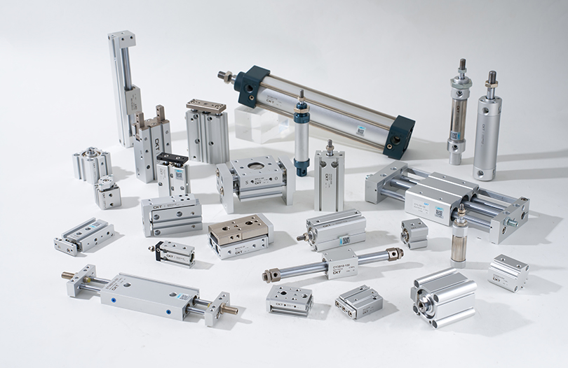
Comparing Double Acting with Magnet to Other Air Cylinder Types
It helps to see where the double acting cylinder with magnet fits relative to alternative cylinder types:
| Cylinder Type | Active Force | Magnet Sensing | Typical Use |
|---|---|---|---|
| Single acting, spring return | Extend only | Yes (optional) | Simple push/clamp, fail-safe return |
| Double acting with magnet | Both directions | Yes (standard) | General automation, most applications |
| Rodless cable cylinder | Both directions | Yes | Long strokes, space-saving |
| Guided/twin-rod cylinder | Both directions | Yes | Anti-rotation, lateral load handling |
| Tandem cylinder | Both directions | Yes | Double force in same bore size |
| Through-rod (double-ended) | Both directions, equal force | Yes | Equal force both strokes, cam actuation |
The double acting cylinder with magnet is the default starting point for almost any new design. You would deviate from it only when a specific constraint — equal force in both directions, lateral loads, extremely long stroke, no space for the extended rod — pushes you toward one of the alternatives.
Installation Best Practices
Getting the most out of a double acting pneumatic cylinder with magnet depends heavily on correct installation. The following practices consistently separate well-running systems from problematic ones.
Alignment
The cylinder's central axis must be parallel to the direction of motion. Misalignment by even 1–2° introduces side loading on the piston rod and rod seal. Over thousands of cycles, this accelerates wear and causes seal leakage. Use floating joints (also called rod eyes with spherical bearings or knuckle joints) at the rod end whenever perfect alignment cannot be guaranteed. Floating joints absorb angular misalignment of up to 3–5° depending on the model.
Cushioning Adjustment
Adjust the end cushioning screws with the cylinder running at operating speed and load. Start with the cushion fully open (minimum restriction) and gradually close it until the cylinder decelerates smoothly without bouncing at the end of stroke. The target deceleration zone is typically the last 10–20 mm of stroke. Overtightening the cushion screw increases cycle time unnecessarily; insufficient cushioning causes impact noise, mechanical stress on the cylinder end caps and the machine frame, and premature failure of the piston assembly.
Sensor Positioning
After installation, power the cylinder and observe where in the stroke the sensor LED illuminates. Slide the sensor so the LED turns on and off consistently at the desired piston position. Allow 2–3 mm of buffer from the mechanical end stop. Tighten the sensor locking screw to the manufacturer's specified torque — typically 0.3–0.8 Nm for small sensors. Under-torqued sensors slip over time; over-torqued sensors crack.
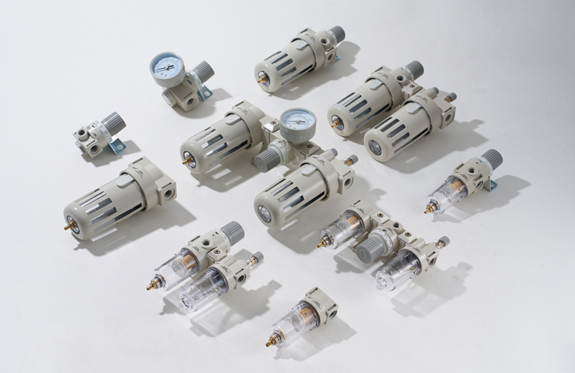
Air Supply Quality
Install a filter-regulator-lubricator (FRL) unit upstream of the directional control valve feeding the cylinder. The filter should remove particles larger than 5 μm and achieve a dew point below the minimum ambient temperature to prevent condensation inside the cylinder. Many modern cylinder seals are designed for non-lubricated operation — check the manufacturer's data before adding lubricant oil, as some seals are designed for dry air and swell when exposed to oil mist.
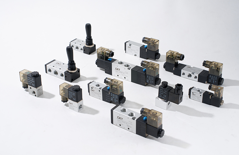
Flow Controls
Install meter-out flow control valves (one per port) to control the speed of extension and retraction independently. Meter-out — throttling the exhaust, not the supply — gives smoother, more controllable motion with varying loads. Meter-in can cause erratic motion under load. Set flow controls gradually while monitoring speed: a rod velocity of 0.1–0.5 m/s is typical for most applications; high-speed applications may run up to 1.5 m/s but will require larger valves and higher-grade cushioning.
Maintenance Schedule and Troubleshooting
Double acting air cylinders are among the most reliable components in a pneumatic system, but they are not maintenance-free. A structured maintenance approach prevents unplanned downtime.
Routine Inspection Points
- Rod seal leakage — a small film of oil is acceptable on a lubricated cylinder; droplets or visible air leakage at the rod seal indicates wear and the need for a seal kit replacement. On non-lubricated cylinders, any visible leakage is a problem.
- Rod surface — inspect for scoring, corrosion, or dents that could damage the rod seal. A damaged rod must be replaced, not just polished, as surface roughness affects seal life dramatically.
- Sensor function — verify the LED on each sensor illuminates at the correct piston position on every shift. A sensor that no longer triggers reliably indicates either a failed sensor or a weakened magnet (extremely rare with neodymium magnets but possible in high-temperature applications).
- Mounting fasteners — check for looseness caused by vibration. Apply thread-locking compound to fasteners in high-vibration environments.
- Air supply pressure — confirm operating pressure at the cylinder inlet matches the design specification. Pressure drops in the supply line indicate undersized tubing or a partially closed valve.
Common Fault Patterns and Causes
- Cylinder not extending or retracting: Check directional valve operation, supply pressure, and whether the flow control valve is fully closed. A blocked exhaust silencer can also prevent motion.
- Slow, sluggish motion: Undersized tubing or fittings, clogged filter, partially closed flow control, or insufficient supply pressure.
- Sensor not triggering: Sensor out of position, failed sensor, or incorrect PLC input wiring. Check sensor LED — if it illuminates but the PLC does not see the signal, the issue is wiring or input card, not the sensor or magnet.
- Cylinder drifting under load: Internal piston seal leak allowing air to bypass the piston. Replace piston seal kit. If the barrel bore is scored, the cylinder body must be replaced.
- Impact noise at end of stroke: Cushioning screws not properly adjusted, or cushion seals worn. Adjust or replace cushion seals.
Planned seal replacement should occur at intervals specified in the manufacturer's service data — typically every 2,000–5,000 km of piston travel or every 2–5 years in moderate-duty applications. Tracking cylinder cycles via the PLC using the sensor signals themselves gives a precise cycle count that can trigger a maintenance alert automatically.
Choosing Between Major Manufacturers
The market for double acting pneumatic cylinders with magnet is mature and competitive. Several manufacturers offer ISO-compliant products with comparable performance, and the decision often comes down to factors beyond the cylinder itself.
- Festo — known for extensive product range including the DSBC (ISO 15552) and ADN (ISO 21287) families. Strong in Europe, extensive documentation and online configuration tools.
- SMC — the world's largest pneumatics manufacturer by revenue. The C95 (ISO 15552) and CQ2 (compact) series are widely stocked globally. SMC's sensor range is particularly extensive.
- Parker Hannifin — the P1D (ISO 15552) and P5S (ISO 6432) series. Strong in North America and heavy industry markets.
- Norgren — RM/92000 series ISO 15552 cylinders; good availability in European markets.
- Airtac / Mindman / CKD — Asian manufacturers offering ISO-compliant products at lower price points, widely used in cost-sensitive OEM applications.
For replacement and MRO purchases, stick with the same manufacturer as the installed unit if possible, to avoid subtle dimensional differences in sensor slot geometry or port positioning. For new machine designs, select based on local availability, delivery lead time, price per unit at your expected annual volume, and the quality of the manufacturer's online product configurator — a good configurator saves significant engineering time during design.
Special Variants Worth Knowing
Beyond the standard double acting air cylinder with magnet, several specialized variants address specific application needs:
Clean Room and Semiconductor Grade
Cylinders intended for ISO Class 3–6 clean rooms use low-outgassing materials, special lubricants or dry-film coatings, and stainless steel external components. The magnet piston function is fully compatible with clean room requirements since the sensor operates externally and no metal particles are generated inside the cylinder during normal operation.
ATEX / Hazardous Area
In explosive atmospheres — paint spray booths, chemical plants, grain handling facilities — both the cylinder and the sensor must be ATEX-certified. The air cylinder itself is inherently safe (no electrical components), but the sensor wiring and housing must meet ATEX Category 2 or 3 requirements. Use only sensors explicitly listed as ATEX-approved with the cylinder model in question.
Corrosion-Resistant Stainless Steel
316 stainless steel barrel, piston rod, and end caps are available from several manufacturers for marine, offshore, pharmaceutical, and food-grade applications where aluminum or carbon steel would corrode. The non-magnetic properties of 316 stainless are compatible with magnet piston sensing — the alloy is austenitic and therefore non-ferromagnetic, so it does not interfere with the sensor's ability to detect the piston magnet's field.
Multi-Position Cylinders
By combining a double acting cylinder with a second cylinder of a different stroke length in tandem, three distinct positions can be achieved: fully retracted, mid-stroke (first cylinder extended, second retracted), and fully extended (both extended). This is a cost-effective alternative to a servo-driven electric actuator when only three discrete positions are required. Each position is verified by a magnet sensor on the respective cylinder.