


Content
- 1 What Is a Double Rod Air Cylinder and Why Does It Matter
- 2 Internal Construction: How a Double Rod Air Cylinder Works
- 3 Double Rod vs. Single Rod Air Cylinder: A Direct Comparison
- 4 Common Series and Specifications in the Market
- 5 Sizing a Double Rod Air Cylinder Correctly
- 6 Industrial Applications Where Double Rod Air Cylinders Excel
- 7 Air Supply and System Requirements for Double Rod Cylinders
- 8 Mounting Configurations and Installation Best Practices
- 9 Maintenance and Troubleshooting for Double Rod Air Cylinders
- 10 Selecting Between Double Rod Air Cylinder Types: A Decision Framework
- 11 Cost Considerations and Total Value Assessment
What Is a Double Rod Air Cylinder and Why Does It Matter
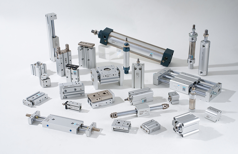
A double rod air cylinder is a pneumatic actuator that features piston rods extending from both ends of the cylinder body rather than just one. This seemingly simple structural difference has significant consequences for how the air cylinder performs in real-world industrial applications. The core advantage is symmetric force output: the cylinder delivers equal push and pull force at any given air pressure, because both strokes act on the same cross-sectional area. With a standard single-rod pneumatic cylinder, the retraction force is always lower than the extension force because the rod occupies part of the piston face on the rod side, reducing the effective pressure area. That asymmetry disappears entirely in a double rod design.
Beyond force balance, the twin-rod structure prevents piston rod rotation during extension and retraction. In many automation sequences—labeling, welding, dispensing, pressing—even a few degrees of rotational drift ruins product quality or causes misalignment. A double rod air cylinder eliminates that risk mechanically, without relying on downstream anti-rotation guides or complex mounting hardware.
This article covers everything a mechanical or automation engineer needs to know before specifying a double rod cylinder: how it works internally, how it compares to other air cylinder types, which series dominate the market, how to size one correctly, and how to avoid the most common installation mistakes.
Internal Construction: How a Double Rod Air Cylinder Works
The internal layout of a double rod air cylinder follows the same fundamental principles as any double-acting pneumatic cylinder, with one critical addition. A piston sits at the center of the bore. Instead of one rod extending outward from the head-end cap, two rods of equal diameter are attached to opposite faces of the piston and pass through sealed glands in both the head-end and cap-end covers.
Two air ports—one at each end of the cylinder barrel—allow compressed air to enter and exhaust alternately. When air enters the head-end port, it pushes the piston toward the cap end, extending one rod while retracting the other. When air enters the cap-end port, the motion reverses. Because both sides of the piston have identical effective areas (both rods share the same diameter), force and velocity are perfectly symmetrical in both directions.
Key Internal Components
- Cylinder barrel: typically extruded aluminum alloy, hard-anodized to resist corrosion and reduce friction
- Piston: carries the primary seal (usually NBR or polyurethane) and a magnetic ring for sensor triggering
- Two piston rods: hardened steel shafts, chrome-plated to HRC 55–60 for rod seal longevity
- Rod seals and scrapers: prevent air leakage and keep contamination out on both ends
- End covers: die-cast aluminum or steel, containing the port threads and cushion adjustment valves
- Air cushions: adjustable needle valves that decelerate the piston near each end of travel to absorb kinetic energy
In guided variants (such as the TN or CXSM series), the two rods pass through bronze or ball-bearing bushings in a front plate, which adds lateral rigidity and further reduces deflection under off-axis loads. This sub-type is sometimes called a twin-rod guided cylinder, dual-rod slide cylinder, or compact guide cylinder, though the operating principle is identical.
Double Rod vs. Single Rod Air Cylinder: A Direct Comparison
Choosing between a single-rod and double rod air cylinder depends on the specific demands of the application. Neither type is universally superior. The table below summarizes the most important practical differences.
| Parameter | Single Rod Air Cylinder | Double Rod Air Cylinder |
|---|---|---|
| Force balance | Unequal extend vs. retract force | Equal force in both directions |
| Rod rotation | Possible without anti-rotation guide | Eliminated by dual-rod geometry |
| Side-load tolerance | Limited; rod deflects under lateral force | High; dual rods distribute shear load |
| Overall length | Shorter overall envelope | Longer—both rods must clear the frame |
| Mount options | Full range including clevis and pivot | Restricted; no clevis or rear flange pivot |
| Work on both ends | No—only one rod end | Yes—tools can be attached to both rod ends |
| Cost | Lower—simpler sealing, fewer parts | Higher due to extra rod, gland, and seals |
| Hydraulic circuit simplification | Not applicable | Possible—equal volumes on both sides enable regenerative circuits |
For applications requiring only linear push or pull in one primary direction—basic clamping, door actuation, simple press work—a single-rod pneumatic cylinder remains the most cost-effective choice. The moment an application demands rotation prevention, equal bidirectional force, or simultaneous tooling on both rod ends, the double rod configuration becomes the correct specification.
Common Series and Specifications in the Market
Several established series define the double rod air cylinder market. Understanding the differences between them helps engineers match the right product to the application without over-specifying.
TN Series — Compact Twin-Rod Guided Cylinder
The TN series is the most widely used compact double rod cylinder in automation. Bore sizes typically range from 10 mm to 32 mm, with strokes from 5 mm to 125 mm, though extended variants exist up to 200 mm. The two rods pass through a front end plate with precision bushings that provide anti-rotation and side-load resistance. Operating pressure is generally 0.1 to 0.8 MPa, making it suitable for standard industrial compressed-air systems at 5–7 bar. The TN footprint is small enough to integrate directly into pick-and-place heads, assembly jigs, and label applicators.
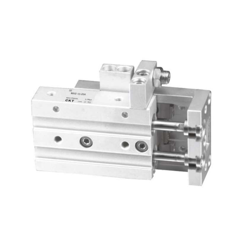
CXSM / CXSW Series — Slide-Type Dual Rod Cylinder
These series replace the classic front-plate guide with an integrated slide block that rides on the two rods via linear ball bearings or bronze bushings. The slide block becomes the mounting surface for tooling, making it easy to attach grippers, sensors, or custom fixtures without additional adapter plates. The CXSM series is particularly favored in high-cycle electronic component assembly lines because the ball-bearing slide produces virtually zero stick-slip, resulting in positioning repeatability of ±0.05 mm or better. Bore sizes from 6 mm to 25 mm keep the overall height very low, useful in confined machine frames.
CS2W / MBW Series — Medium to Large Bore Double Rod
For heavier applications, medium-bore double rod air cylinders are available in bore sizes from 125 mm to 160 mm with strokes up to 1,200 mm depending on mounting. These cylinders use aluminum die-cast covers and tie-rod construction. The CS2W-type achieves approximately 50% weight savings versus steel counterparts at the same bore, important when the cylinder is part of a moving machine axis. Air cushions are standard at both ends on this class of cylinder to absorb the kinetic energy of larger piston-rod-load assemblies.
MGP / MGPM Series — Compact Guide Cylinder with Dual External Rods
Technically a guided cylinder rather than a pure double rod air cylinder, the MGP series places two external guide rods alongside a central drive piston, all housed in a low-profile aluminum body. It handles higher side loads than any twin-rod-only design because the guide rods are positioned at maximum moment arm from the centerline. Bore sizes span 12 mm to 63 mm, with operating pressures up to 1.0 MPa. This series appears frequently in pressing and marking operations where accuracy under load is critical.
Sizing a Double Rod Air Cylinder Correctly
Incorrect sizing is the single most common cause of premature air cylinder failure or unsatisfactory performance. The calculation process for a double rod cylinder differs slightly from a single-rod type, particularly because the equal-area piston simplifies force math while space constraints become a harder limit.
Step 1: Define the Required Force
Calculate the actual load the cylinder must move or hold. For dynamic applications—anything the cylinder is accelerating—multiply the static load by a factor of 2.0 to account for acceleration forces. For static holding or clamping, use a factor of 1.25. Never size at 100% theoretical force, because friction, back-pressure in the exhaust line, and wear all reduce effective output over time. The standard industry load factor for dynamic pneumatic applications is 0.6 to 0.7; that means the cylinder's theoretical force output should be 1.4 to 1.7 times the load.
Step 2: Calculate Required Bore
Because both sides of a double rod cylinder piston have equal area, the force formula is the same for extension and retraction:
F = (π / 4) × D² × P
Where F is force in Newtons, D is bore diameter in meters, and P is operating gauge pressure in Pascals. At 0.5 MPa (5 bar), a 25 mm bore double rod cylinder produces approximately 245 N of force. A 40 mm bore at the same pressure produces approximately 628 N. Round up to the next standard bore size after applying the load factor.
Step 3: Verify Space Envelope
The most overlooked constraint in double rod cylinder selection is total installed length. Because one rod extends at all times, the machine frame must accommodate the full cylinder body length plus the full stroke on both sides. Total frame clearance required = cylinder body length + (2 × stroke). For a cylinder with a 100 mm body and a 50 mm stroke, the frame slot must be at least 200 mm. Forgetting to account for the rear rod extension has caused costly machine redesigns during commissioning.
Step 4: Check Buckling Risk on Long Strokes
If the stroke exceeds 10 to 15 times the rod diameter, compressive rod buckling becomes a risk. For a 12 mm rod, the practical maximum unsupported compressive stroke is around 120–180 mm. Beyond that, consult ISO 15552 buckling nomograms or increase the rod diameter. In guided double rod cylinders, the second rod distributes the compressive load across two members, raising the safe stroke limit significantly compared to single-rod designs.
Industrial Applications Where Double Rod Air Cylinders Excel
The unique mechanical properties of the double rod configuration make it the preferred actuator in a defined set of industrial scenarios. Knowing these scenarios helps engineers quickly determine whether a standard single-rod pneumatic cylinder or a specialized double rod design is the right starting point.
Automated Assembly and Pick-and-Place Systems
Electronic component assembly machines, PCB handling systems, and semiconductor packaging equipment require actuators that cycle thousands of times per hour at precise, repeatable positions. The anti-rotation behavior of a double rod air cylinder ensures that a vacuum cup, gripper, or nozzle attached to the rod end returns to exactly the same orientation with every stroke. At typical operating speeds of 200–500 mm/s and cycle rates of 60–120 per minute, even a 1° rotational drift per cycle accumulates to visible misalignment within minutes.
Clamping and Fixturing with Bidirectional Force
Welding fixtures, machining vises, and press tooling often need to clamp with controlled force in both directions—clamping the workpiece on extension and positively releasing it on retraction against a spring or friction force. A double rod air cylinder provides equal clamping and release force at the same supply pressure, eliminating the need to adjust pressure regulators between the clamp and release sequences. This simplifies the pneumatic circuit and reduces the number of pressure control valves required.
Synchronous Multi-Axis Motion
When two air cylinders must move together in a gantry or transfer system, equal flow consumption in both directions makes flow balancing simpler. Because a double rod cylinder displaces the same volume of air on each stroke, two cylinders supplied from a common manifold with matched flow controls will travel at identical speed and arrive at end position simultaneously. In practice, this symmetric air consumption reduces system tuning time by eliminating the differential flow corrections needed for single-rod cylinder pairs.
X-Y Slide Tables and Linear Stages
Dual guide-rod cylinders of the CXSM or slide-type class are regularly stacked in perpendicular orientations to build compact X-Y stages for laser marking, dispensing, or inspection. The T-slot mounting profiles on guided double rod cylinders allow them to be bolted directly to each other without machined adapter brackets, cutting build time and part count. A typical two-axis stage built from 16 mm bore CXSM cylinders weighs under 800 grams and occupies a footprint of roughly 80 × 80 mm, fitting inside compact benchtop automation cells.
Textile, Printing, and Paper Handling Machinery
Web-handling machines subject actuators to significant lateral and torsional loads from moving material. A standard single-rod pneumatic cylinder deflects under these side loads, causing wear on the rod seal and eventual leakage. Double rod cylinders distribute the lateral force between two rod-bushing interfaces, significantly extending seal life in these applications. Several textile machinery manufacturers report seal replacement intervals of over 50 million cycles using properly sized double rod cylinders versus 15–20 million cycles with comparable single-rod units.
Food, Beverage, and Pharmaceutical Packaging
High-precision filling, capping, and labeling machines demand repeatable stroke positions and consistent force to handle fragile containers. Glass bottles, blister packs, and vials break or jam if the actuator force is uncontrolled. The equal extend and retract force of a double rod air cylinder simplifies the pressure-setting procedure during machine commissioning, and the anti-rotation behavior keeps applicator heads consistently aligned with container features.
Air Supply and System Requirements for Double Rod Cylinders
A double rod air cylinder performs reliably only when the compressed air supply meets basic quality and pressure standards. Running a pneumatic cylinder on dirty, wet, or incorrectly pressurized air is the fastest path to premature seal failure and positioning errors.
Filtration
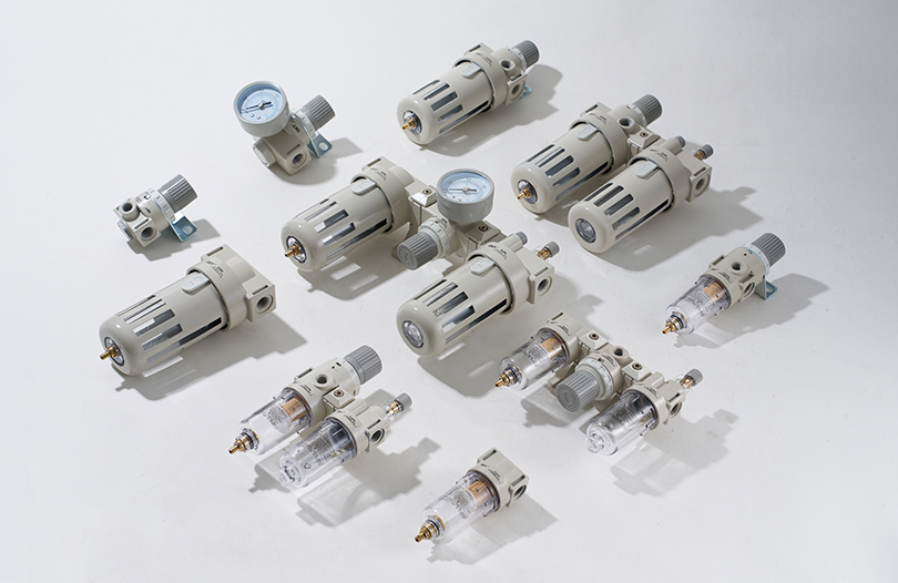
All pneumatic actuators, including double rod cylinders, require air filtered to 40 µm or finer as a minimum (ISO 8573-1:2010 Class 4). Particulates larger than this act as abrasives against the piston and rod seals, accelerating wear. For precision guided cylinders (CXSM, MGP), filtration to 5 µm is recommended to protect the linear bearings. Always install an FRL (Filter-Regulator-Lubricator) unit upstream of the cylinder circuit, or use non-lubricated cylinders with a coalescing filter if oil-free operation is required.
Operating Pressure
Standard double rod air cylinders are rated for operating pressure between 0.05 MPa (0.5 bar) minimum start-up pressure and 1.0 MPa (10 bar) maximum. Most industrial compressed-air systems run at 0.5–0.7 MPa (5–7 bar), which sits comfortably in the middle of this range. Running at the absolute maximum pressure accelerates seal wear and reduces cushion effectiveness. The most efficient operating point for a correctly sized air cylinder is the lowest pressure that produces the required force with a 1.4× safety factor applied—typically in the 0.4–0.6 MPa range for most automation tasks.
Temperature
Standard NBR (nitrile butadiene rubber) seals in most double rod cylinders operate reliably between −20°C and +80°C. For applications near ovens, dryers, or heat-sealing stations, upgrade to Viton (FKM) seals rated to +150°C. At the cold end, sub-zero environments such as freezer conveyor systems may require low-temperature NBR compounds or PTFE seals to prevent seal hardening and blow-by.
Mounting Configurations and Installation Best Practices
Correct installation is critical for any pneumatic actuator, but for a double rod air cylinder the requirements are particularly strict because misalignment causes twice the rod-seal stress compared to a single-rod unit.
Available Mount Styles
Double rod air cylinders support the following mounting configurations:
- Foot mount (LB): brackets welded or bolted to the cylinder body; most common in fixed-travel applications
- Front flange (FA): flange bolted to the head-end cover; useful when the cylinder must be mounted inside a housing
- Cap-end flange (FB): flange at the cap end, used when access to the front rod is restricted
- Trunnion mount (TC): allows the cylinder to pivot on a fixed axis; compatible with some double rod designs but verify with the manufacturer
- T-slot body (guided series): side-mounted T-slots along the cylinder barrel allow adjustment of position and direct mounting to profiles
Note that clevis and pivot (rear spherical) mounts are not available on most double rod designs. The protruding rear rod prevents those bracket geometries. If the application requires a pivoting cylinder, a single-rod design with an anti-rotation guide external to the cylinder is typically the better solution.
Alignment During Installation
Both rod ends must be in perfect coaxial alignment with the direction of travel. Any angular offset at the rod end connection introduces a bending moment at the rod seal, which accelerates wear. For guided dual-rod cylinders in particular, the slide block load surface should be perpendicular to the rods within 0.05 mm across the mounting face. Use a dial indicator to verify alignment before final bolt torquing. Floating joints (rod eye with spherical bearing) at the load connection absorb minor misalignments, but they do not substitute for proper mechanical alignment at installation.
Cushion Adjustment
Both ends of a double rod air cylinder have adjustable cushion needle valves. These must be set for each specific load and speed combination. The correct cushion adjustment produces a smooth deceleration with no audible end-stop impact and no visible rebound of the piston. Start with the needle valve fully open (minimum cushioning), then gradually close it until impact noise disappears. Over-tightening the cushion—especially on the extension stroke—will dramatically reduce cycle rate because the cylinder takes longer to reach end position. The optimal setting is the loosest needle position that still eliminates mechanical impact.
Maintenance and Troubleshooting for Double Rod Air Cylinders
A well-specified and correctly installed double rod air cylinder requires minimal routine maintenance. The most common failure modes are predictable and preventable.
Rod Seal Leakage
External air leakage at the rod glands is the most frequently reported issue. It is almost always caused by one of three factors: contaminated air supply (abrasive particles cutting the seal lip), rod surface scoring (from side loads or installation damage), or seal hardening from temperature extremes. Inspect the rod surface for scoring marks before replacing seals—installing a new seal on a damaged rod produces immediate re-failure. Use a 600-grit polishing cloth on minor rod scratches before reassembly.
Reduced Speed or Force
If a double rod air cylinder runs noticeably slower or weaker on one stroke direction than the other—in a design where both should be equal—the probable causes are a partially blocked port, a partially clogged flow control valve, or a degraded piston seal allowing bypass between the two chambers. Isolate the cylinder and pressure-test each chamber individually: apply 0.5 MPa to one port while blocking the other and monitoring pressure decay over 60 seconds. A pressure drop of more than 5% per minute indicates piston seal bypass.
Position Drift in Guided Cylinders
If a guided double rod cylinder begins to show increasing position error at the end of stroke, worn linear bearings or bronze bushings in the end plate are usually responsible. Bearing wear allows the slide block to rock slightly, shifting the contact point of any attached tooling. Replace bushings at the manufacturer-specified interval, typically every 5–10 million cycles for bronze and every 20–50 million cycles for ball-bearing types, depending on load.
End-Cover Cracking on High-Cycle Applications
On cylinders cycled more than 20 million times per year, fatigue cracking can appear in die-cast aluminum end covers, typically radiating from the port boss or tie-rod hole. This is a sign that the cushion setting was too hard, producing repeated shock loads at end of stroke. Re-tune the cushion valves and inspect the mounting for resonant vibration, which multiplies impact stress. If cover cracking recurs after retuning, switch to a forged or steel-body cylinder in the same bore series.
Selecting Between Double Rod Air Cylinder Types: A Decision Framework
With several distinct series available, engineers often face uncertainty about which double rod cylinder type best fits their application. The following criteria provide a structured way to narrow the choice.
| Application Requirement | Recommended Series | Reason |
|---|---|---|
| Compact footprint, short stroke, anti-rotation | TN Series | Smallest envelope, simple construction, low cost |
| High cycle rate, zero stick-slip, tooling on slide | CXSM / CXSW | Ball-bearing slide, integrated mounting surface |
| Heavy load, large bore, long stroke | CS2W / MBW | 125–160 mm bore, tie-rod construction, cushions standard |
| Maximum side-load resistance at low bore | MGP / MGPM | External guide rods at wide spacing provide best moment arm |
| X-Y stage without machined brackets | CXSM stacked | T-slot bodies bolt directly together in orthogonal orientation |
When operating pressure, seal material, or rod material deviates from standard, contact the cylinder manufacturer for a custom configuration. Most major suppliers offer non-standard seals (Viton, PTFE), stainless-steel rod and barrel options for washdown environments, and special port positions or thread standards (Rc, NPT, G) to match existing pneumatic circuit hardware.
Cost Considerations and Total Value Assessment
A double rod air cylinder costs more upfront than an equivalent bore single-rod pneumatic cylinder, primarily because it contains an additional rod, a second rod seal and scraper, and a second gland bore machined in the cap-end cover. For a typical 20 mm bore unit with a 50 mm stroke, the price premium over a comparable single-rod design is roughly 30–60% depending on the series and supplier.
However, in applications where a single-rod cylinder would require an external anti-rotation guide, the economics often reverse. An anti-rotation guide rod assembly—purchased separately and mounted alongside a standard air cylinder—typically costs more than the premium for a purpose-built double rod cylinder, adds complexity, and increases the overall envelope size. In high-cycle applications where downtime is expensive, the extended seal life and reduced maintenance of a correctly specified double rod air cylinder produces a measurably lower total cost of ownership over a three-to-five-year horizon.
The correct question is not whether the double rod cylinder is cheaper than a single-rod unit, but whether it is cheaper than the single-rod unit plus all the external hardware and maintenance costs required to make it perform equivalently in the application.


