
Content
- 1 What Are the Different Types of Air Cylinders?
- 2 Single-Acting Air Cylinders
- 3 Double-Acting Air Cylinders
- 4 Telescoping Air Cylinders
- 5 Rodless Air Cylinders
- 6 Rotary Air Cylinders
- 7 Compact and Guided Air Cylinders
- 8 Comparison of Air Cylinder Types at a Glance
- 9 Cylinder Mounting Styles and Their Impact on Performance
- 10 Key Specifications to Understand When Selecting Air Cylinders
- 11 Maintenance Factors That Extend Air Cylinder Service Life
- 12 How to Choose the Right Type of Pneumatic Cylinder
What Are the Different Types of Air Cylinders?
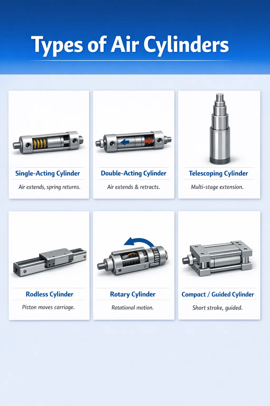
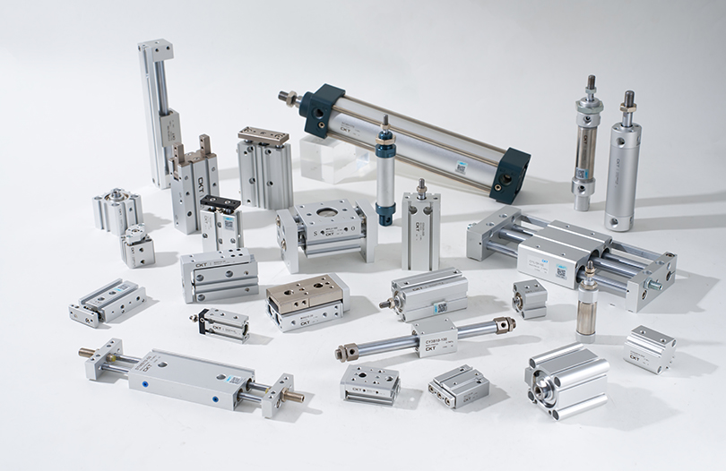
Air cylinders — also called pneumatic cylinders — convert compressed air energy into mechanical linear or rotary motion. There are six primary types of air cylinders used across industrial, automotive, and manufacturing applications: single-acting cylinders, double-acting cylinders, telescoping cylinders, rodless cylinders, rotary cylinders, and compact/guided cylinders. Each type serves a distinct mechanical purpose, and choosing the wrong one can lead to premature wear, energy waste, or outright system failure.
Understanding these categories is not just academic — the global pneumatic cylinder market was valued at approximately $14.2 billion in 2023 and is projected to grow steadily through 2030, driven by automation demand in packaging, food processing, and automotive assembly. The right cylinder selection directly impacts cycle time, energy consumption, and maintenance intervals.
Single-Acting Air Cylinders
Single-acting cylinders use compressed air to move the piston in one direction only. The return stroke is accomplished by an internal spring or an external mechanical force such as gravity. These are among the simplest and most cost-effective pneumatic cylinders available.
How Single-Acting Cylinders Work
Compressed air enters through a single port and pushes the piston forward. When air pressure is released, the internal spring pushes the piston back to its original position. Because a spring is doing half the work, the effective output force is reduced by the spring resistance — typically between 10% and 20% depending on spring stiffness and cylinder size.
Common Applications
- Clamping and holding workpieces during machining
- Stamping and punching operations where the return stroke requires no force
- Door and gate actuators where gravity aids the return
- Brake mechanisms and safety locking devices
- Agricultural equipment such as seed drills and planting mechanisms
Single-acting cylinders are the preferred choice when air consumption needs to be minimized, since air is only consumed on the working stroke. In high-cycle applications running 50–100 cycles per minute, this translates to meaningful compressed air savings over the course of a production shift.
Limitations to Consider
The stroke length of single-acting cylinders is limited because longer strokes require longer springs, which take up bore space and reduce usable cylinder area. In practice, most manufacturers limit spring-return cylinders to strokes of 100 mm (approximately 4 inches) or less. Beyond that, a double-acting design becomes more practical.
Double-Acting Air Cylinders
Double-acting cylinders are the most widely used type of pneumatic cylinder in industrial automation. They use compressed air to power both the extend and retract strokes, giving the operator full control over force and speed in both directions.
Construction and Operating Principle
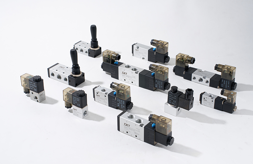
A double-acting cylinder has two air ports — one on each side of the piston. When air enters the cap-end port, the piston extends. When air is directed into the rod-end port, the piston retracts. A directional control valve (usually a 4/2 or 5/2 solenoid valve) alternates airflow between the two ports. Because no spring is involved, the full bore area contributes to extend force, making these cylinders considerably more powerful than their single-acting counterparts of the same bore diameter.
Force Calculation Differences Between Strokes
One important distinction: the extend and retract forces are not equal. On the extend stroke, force is calculated using the full bore area. On the retract stroke, the piston rod occupies part of the bore, so the effective area — and therefore the retract force — is slightly less. For a cylinder with a 50 mm bore and a 20 mm rod at 6 bar, the extend force is approximately 1,178 N while the retract force drops to roughly 990 N. This asymmetry must be factored into designs where retract force is critical.
Typical Use Cases
- Pick-and-place automation in assembly lines
- Conveyor diverters and sorting systems
- Injection molding machine clamps and ejectors
- Robotic end-of-arm tooling
- Automotive body welding and pressing fixtures
Double-acting air cylinders are available in bore sizes ranging from 8 mm to over 320 mm, covering force outputs from a few newtons up to tens of kilonewtons. This wide range makes them adaptable to nearly any industrial application.
Telescoping Air Cylinders
Telescoping cylinders are designed for applications where a long stroke is needed but the retracted (collapsed) length must remain short. They achieve this by using multiple nested tubes — called stages or sleeves — that extend sequentially one inside the other.
Single-Acting vs. Double-Acting Telescoping Designs
Telescoping cylinders are available in both single-acting and double-acting configurations. Single-acting versions are simpler and cheaper but rely on gravity or load weight for retraction, making them suitable mostly for vertical lifting. Double-acting telescoping cylinders can extend and retract under power, allowing horizontal or inverted mounting — though their construction is significantly more complex and their cost is substantially higher.
Key Applications
- Dump trucks and tipper bodies requiring 3–5 stage cylinders
- Scissor lifts and aerial work platforms
- Theatre stage machinery and entertainment rigging
- Fire truck ladder extensions
A three-stage telescoping cylinder with a collapsed length of 600 mm can achieve a fully extended stroke of over 1,700 mm — nearly three times its retracted length. This spatial efficiency is impossible to achieve with a conventional single-rod cylinder.
Force Reduction Across Stages
One important engineering consideration: each successive stage in a telescoping cylinder has a smaller bore than the previous one, meaning output force decreases as the cylinder extends further. Designers must size the cylinder based on the worst-case load position, which usually occurs at or near full extension when force is at its minimum.
Rodless Air Cylinders
Rodless pneumatic cylinders eliminate the traditional piston rod entirely, instead transmitting the piston's motion to an external carriage or slide through a slot or magnetic coupling. This design doubles the effective stroke for a given installation length compared to a conventional rod cylinder, making them extremely valuable in space-constrained environments.
Mechanical-Slot Rodless Cylinders
In a mechanical-slot (or band) design, the cylinder body has a longitudinal slot. The internal piston is connected to an external carriage through this slot. A flexible metal or plastic band seals the slot on both sides of the connection point to prevent air leakage. These cylinders can handle direct side loads and are suitable for applications requiring high guiding accuracy.
Magnetically Coupled Rodless Cylinders
Magnetically coupled rodless cylinders use a sealed internal piston fitted with strong permanent magnets. An external carriage fitted with opposing magnets follows the piston's movement through the cylinder wall without any physical slot. This completely sealed design is ideal for clean-room, food-grade, and washdown environments because there is no opening for contamination to enter or lubricants to escape. The trade-off is a lower maximum side-load capacity compared to slotted versions.
Where Rodless Cylinders Excel
- Linear transfer units in packaging and labeling machines
- Horizontal shuttle systems in CNC machining centers
- Medical device manufacturing where contamination is a concern
- Gantry systems and multi-axis positioning stages
Standard rodless cylinders are available with stroke lengths from 50 mm to over 10,000 mm. For very long strokes, anti-rotation guides and center supports are recommended to prevent barrel sag and carriage drift.
Rotary Air Cylinders
While most pneumatic cylinders produce linear motion, rotary air cylinders convert compressed air energy into angular (rotational) motion. They are often called pneumatic rotary actuators. These are distinct from air motors — rotary cylinders produce limited-angle rotation (typically 90°, 180°, or 270°) rather than continuous spinning.
Rack-and-Pinion Rotary Actuators
The most common rotary cylinder design uses one or two linear pistons connected to a rack gear, which drives a pinion shaft. Air pushes the piston(s), the rack rotates the pinion, and torque is transmitted to the output shaft. Dual-rack designs balance the load and nearly double the output torque for a given bore size. Rotation angles are adjustable via external stops, typically between 0° and 270°.
Vane-Type Rotary Actuators
Vane actuators use a paddle (vane) attached to the output shaft inside a circular housing. Air pressure on one side of the vane rotates the shaft; air on the opposite side rotates it back. Single-vane designs allow up to 280° of rotation, while double-vane designs are limited to about 100° but offer higher torque in a more compact body.
Typical Applications
- Valve actuation in process piping (quarter-turn ball valves, butterfly valves)
- Indexing tables and rotary positioning in assembly automation
- Robotic wrist and elbow joints
- Part flipping and orientation in transfer lines
- Door and hatch actuators on industrial equipment
Compact and Guided Air Cylinders
Compact and guided cylinders are specialized variants that address two very specific challenges: extremely tight installation spaces and applications that require the piston rod to resist rotation or lateral loads without relying on external guide systems.
Short-Stroke Compact Cylinders
Also called pancake cylinders or flat cylinders, these units have minimal body length relative to their bore. Strokes are typically limited to 1 mm to 50 mm. Their flat profile allows them to be mounted in confined areas where a standard cylinder body would simply not fit. Common use cases include PCB pressing, label dispensing, and micro-positioning in semiconductor equipment.
Guided (Twin-Rod) Cylinders
Guided cylinders incorporate two parallel piston rods connected to a common front plate. This configuration prevents rod rotation and provides high resistance to moment loads (off-center forces). Guided cylinders can handle side loads 4 to 10 times greater than a standard single-rod cylinder of the same bore, eliminating the need for a separate external linear guide in many applications.
Slide Unit Cylinders
Slide unit cylinders integrate a guided carriage directly onto the cylinder body. The carriage rides on linear bearings or recirculating ball rails and provides a flat mounting surface for tooling or workpiece fixtures. These all-in-one units reduce design and assembly time significantly in custom automation projects. Festo, SMC, and Parker all offer modular slide units with interchangeable stroke lengths and bearing configurations.
Comparison of Air Cylinder Types at a Glance
| Cylinder Type | Stroke Direction | Typical Max Stroke | Air Consumption | Best For |
|---|---|---|---|---|
| Single-Acting | One direction (air), spring return | ~100 mm | Low | Clamping, braking, safety functions |
| Double-Acting | Both directions (air) | Up to 2,000 mm+ | Moderate–High | General automation, high-cycle tasks |
| Telescoping | One or both (multi-stage) | 3× collapsed length | Moderate | Lifting, dumping, space-limited long strokes |
| Rodless | Both directions (no rod) | Up to 10,000 mm | Moderate | Long-stroke linear transfer, clean rooms |
| Rotary | Angular (limited rotation) | Up to 280° | Low–Moderate | Valve actuation, indexing, flipping parts |
| Compact/Guided | Linear (short or guided) | ~50–500 mm | Low–Moderate | Side loads, anti-rotation, tight spaces |
Cylinder Mounting Styles and Their Impact on Performance
Regardless of cylinder type, the mounting configuration has a direct effect on performance, longevity, and load management. Standard ISO 15552 and NFPA T3.6.7 cylinders offer interchangeable mounting interfaces, which simplifies replacements across different manufacturers.
- Foot mount (MS1/MS2): Fixed base mounting; ideal for in-line push/pull with well-aligned loads. Misalignment transfers bending stress to the rod and seals.
- Flange mount (MF1/MF2): Front or rear flange bolts directly to a machine plate. Excellent for applications with rigid, in-line loads.
- Clevis mount (MP1/MP3): Allows the cylinder to pivot as the load moves in an arc. Used extensively in door openers, linkage mechanisms, and tilting systems. A rod-end clevis (MP5) should be used at the rod side for full articulation.
- Trunnion mount (MT1/MT4): Allows the cylinder body to swing in one plane. Common in industrial presses and material handling where pivot motion is required.
Incorrect mounting is one of the most common causes of premature seal failure and rod scoring. Studies by leading pneumatic cylinder manufacturers indicate that over 30% of cylinder failures in the field are attributable to misalignment and improper mounting rather than material or manufacturing defects.
Key Specifications to Understand When Selecting Air Cylinders
Selecting an air cylinder goes beyond just picking a type. Several technical parameters must be evaluated together to ensure the cylinder performs reliably over its intended service life.
Bore Diameter and Output Force
Output force is determined by the formula F = P × A, where P is the supply pressure and A is the effective piston area. At a standard supply pressure of 6 bar (87 psi), a 50 mm bore cylinder produces approximately 1,178 N on the extend stroke, while an 80 mm bore cylinder produces roughly 3,016 N. Bore sizes are standardized per ISO 6432 and ISO 15552 to simplify sizing calculations and sourcing.
Stroke Length and Buckling Risk
For long-stroke cylinders under compressive loads, the piston rod can buckle (column failure) if the rod diameter is undersized. Engineers use Euler's column formula to check buckling limits, and most manufacturers provide load-stroke charts that automatically incorporate a safety factor of 3:1 to 5:1. When a standard rod diameter is insufficient, oversize rod options or external guide systems should be specified.
Operating Temperature and Seal Material
Standard NBR (nitrile) seals cover operating temperatures from -20°C to +80°C. For elevated temperatures up to 200°C, silicone or PTFE seals are used. For low-temperature environments (as cold as -40°C), specially formulated polyurethane or low-temp nitrile compounds are available. Seal material selection is also influenced by media compatibility — for example, if the cylinder is used in a food processing environment with regular washdown using caustic cleaning agents, EPDM seals and stainless steel bodies are the correct specification.
End-of-Stroke Cushioning
At high cycle speeds, a piston reaching the end of its stroke without cushioning creates significant mechanical impact, generating noise and accelerating wear on internal components. Adjustable pneumatic cushions trap a small volume of air near the end of stroke, creating a progressive deceleration. Properly adjusted cushions can reduce impact forces by 80% to 95% compared to uncushioned cylinders running at the same speed and load.
Maintenance Factors That Extend Air Cylinder Service Life
Even the highest-quality pneumatic cylinder will fail prematurely if the system it operates in is not properly maintained. The following factors are most critical.
Air Quality and Filtration
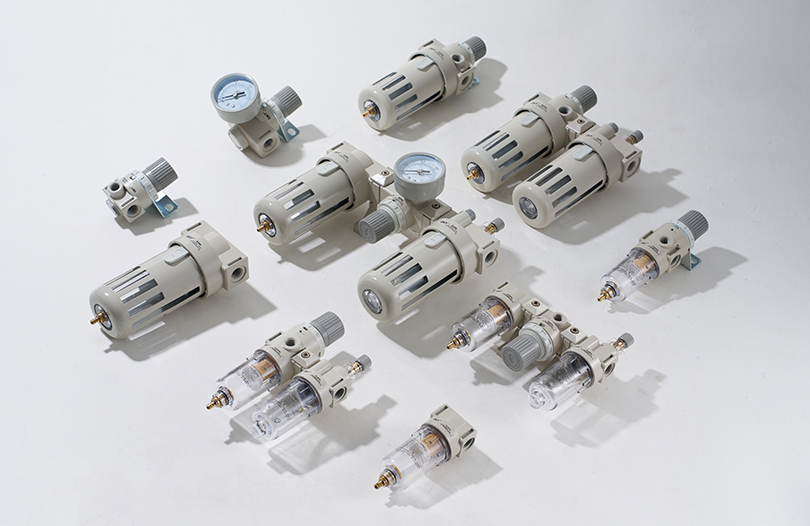
Moisture and particulate contamination in compressed air are the leading causes of internal corrosion and seal degradation. ISO 8573-1 Class 3 air quality (particles ≤ 5 µm, pressure dew point ≤ +3°C, oil concentration ≤ 1 mg/m³) is generally accepted as a minimum standard for pneumatic cylinders. Using a proper FRL (filter-regulator-lubricator) unit on each circuit extends seal life by two to three times compared to unfiltered, unlubricated systems.
Lubrication Practices
Modern pneumatic cylinders are frequently supplied pre-lubricated with long-life grease and designed for non-lubricated air systems. Adding oil mist lubrication to such cylinders can actually flush out the factory-applied grease and shorten service life. Always confirm with the manufacturer whether air-line lubrication is recommended or contraindicated for a specific cylinder model.
Rod Wiper and External Contamination
In dusty or dirty environments, debris adhering to the piston rod is drawn back into the cylinder on each retract stroke, acting as an abrasive on the rod seal. Rod wiper seals — also called scraper rings — are a standard feature on most industrial cylinders but should be inspected and replaced as part of a preventive maintenance schedule, typically every 6 to 12 months in high-contamination environments.
How to Choose the Right Type of Pneumatic Cylinder
Narrowing down the correct cylinder type for a given application involves working through a straightforward decision process based on functional requirements.
- Define the motion type: Is the required motion linear, angular, or rotational? Linear motion points to standard, rodless, compact, or guided cylinders. Angular motion points to rotary actuators.
- Determine force requirements: Calculate the load including friction, inertia, and any vertical gravity components. Add a safety factor of at least 1.5× and select a bore diameter from manufacturer force tables.
- Establish the stroke: If the stroke is short and space is tight, a compact cylinder is appropriate. If the stroke is long but installation length is restricted, a rodless or telescoping cylinder should be considered.
- Assess environmental conditions: Temperature extremes, chemical exposure, washdown requirements, and dust levels all influence body material, seal choice, and surface finish specifications.
- Check cycle rate and duty cycle: High-speed, high-cycle applications require proper cushioning, adequate port sizing, and potentially thermally robust seal compounds to handle the heat generated by repeated compression.
- Evaluate side-load and moment-load requirements: If the cylinder will be subjected to off-axis forces, a guided cylinder or external linear guide is essential to prevent premature rod seal and bushing wear.
By following this structured approach, most engineers can confidently specify the right pneumatic cylinder type and size on the first attempt, avoiding costly redesigns and replacement cycles later in the project.