

Content
- 1 The Short Answer: How to Check an Air Cylinder
- 2 Tools and Preparation Before You Start
- 3 Checking for Air Leaks: The Most Critical Step
- 4 Inspecting the Piston Rod for Wear and Damage
- 5 Checking Operating Pressure and Cylinder Performance
- 6 Inspecting Seals: When to Replace Without Disassembly
- 7 Checking Cylinder Mounting and Alignment
- 8 Inspecting Cushions, Ports, and End-of-Stroke Behavior
- 9 Lubrication Check: Oil-Free vs. Lubricated Cylinders
- 10 Checking the Air Cylinder Barrel and End Caps
- 11 Complete Air Cylinder Inspection Checklist
- 12 How Often Should You Inspect a Pneumatic Cylinder
- 13 Common Air Cylinder Problems and Their Root Causes
- 14 When to Replace the Entire Air Cylinder vs. Repair It
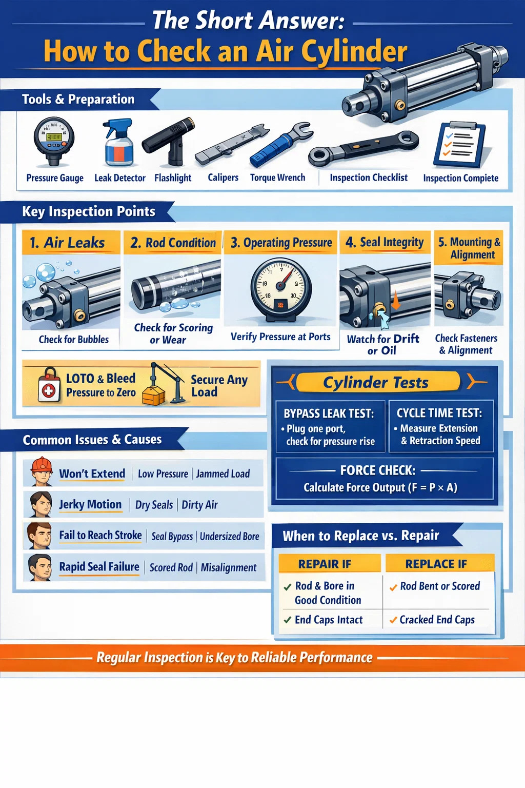
The Short Answer: How to Check an Air Cylinder
To check an air cylinder, you need to inspect it across five core areas: air leakage, operating pressure, piston rod condition, seal integrity, and mounting stability. A healthy pneumatic cylinder should extend and retract smoothly without hesitation, hold pressure without audible leaks, and show no visible oil seepage or rod scoring. If any of these conditions fail, the cylinder requires immediate attention before returning it to service.
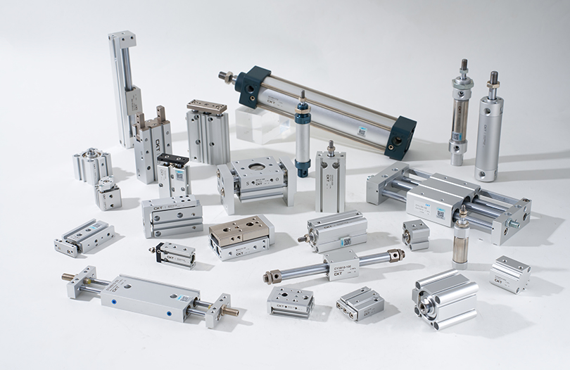
Most air cylinder failures don't happen suddenly. They develop gradually through wear, contamination, or improper lubrication. By knowing what to look for and when to look, you can catch problems at an early stage — before they cause machine downtime, product defects, or safety incidents. The inspection process outlined below applies to standard double-acting pneumatic cylinders, single-acting cylinders, and most compact or guided cylinder variants used in industrial automation.
Tools and Preparation Before You Start
Before touching the air cylinder, gather the right tools and make the work area safe. Skipping preparation is one of the most common reasons inspection results are missed or misread.
What you'll need
- Digital or analog pressure gauge (matched to your system's operating range)
- Soapy water solution or commercial leak detection spray
- Clean lint-free cloth
- Flashlight or inspection lamp
- Torque wrench for checking fastener tightness
- Calipers or micrometer for rod diameter measurement (for detailed inspections)
- Maintenance logbook or inspection checklist form
Safety steps before inspection
Always isolate the compressed air supply to the circuit containing the cylinder. Use a lockout/tagout (LOTO) procedure on the air supply valve. Bleed the downstream pressure to zero using the system's manual exhaust or a bleed valve. Confirm zero pressure on the gauge before touching any fitting, port, or fastener. Compressed air at even modest shop pressures — typically 80 to 120 PSI (5.5 to 8.3 bar) — can cause serious injury if fittings are loosened under pressure.
If the cylinder is part of a vertical load-bearing application (holding a press head, clamp, or lifting fixture), mechanically support the load before depressurizing. Never rely on air pressure alone to hold a load during inspection.
Checking for Air Leaks: The Most Critical Step
Air leakage is the single most common failure mode in pneumatic cylinders. Even a small leak wastes compressed air continuously, driving up energy costs and reducing actuator force. A leak as small as a 1mm diameter orifice at 7 bar can waste over 3,600 liters of free air per hour, costing hundreds of dollars annually in electricity alone — per cylinder.
External leaks
Re-pressurize the cylinder under controlled, supervised conditions. Apply soapy water or leak detection spray to all external surfaces: port fittings, tie rod nuts, end cap joints, rod seal area (where the piston rod exits the front cap), and any cushion needle valve screws. Watch for bubbles forming and growing. A slow leak may take 10–15 seconds to show visible bubbling, so don't rush this step.
Pay special attention to the rod seal zone. Bubbles consistently forming around the rod as it strokes indicate a worn rod seal or a damaged wiper seal. This is especially common in cylinders that have accumulated more than 5 million cycles or have been operating in dirty environments where particulates accelerate lip seal wear.
Internal leaks (bypass leaks)
An internal leak — where air bypasses the piston seals and crosses from one chamber to the other — is harder to detect visually but causes just as much trouble. The symptom is typically sluggish or drifting motion: the cylinder creeps when it should hold position, or it won't fully extend or retract under load even with correct supply pressure.
To test for bypass leaks without disassembly: with the cylinder at the end of stroke in either direction, pressurize one port and plug the opposite exhaust port. If pressure in the plugged chamber builds over time, air is crossing the piston — confirming a worn piston seal. A healthy cylinder should show zero pressure rise in the sealed chamber over 60 seconds.
Inspecting the Piston Rod for Wear and Damage
The piston rod is one of the most exposed components in a pneumatic cylinder. It cycles in and out hundreds of thousands of times, exposed to the surrounding environment on every extension stroke. Even a minor surface defect on the rod will accelerate rod seal wear — turning what would be a simple seal replacement into repeated maintenance cycles.
Visual rod inspection
Wipe the rod clean with a lint-free cloth and inspect its full exposed length under good lighting. Look for:
- Scoring or scratches — longitudinal scratches running along the rod axis allow air to escape past the rod seal and are cause for immediate rod replacement or repolishing.
- Corrosion or pitting — rust spots or pitting on chrome-plated rods break down the seal contact surface. Even light surface rust that doesn't wipe off is a warning sign.
- Dents or flat spots — these indicate an external impact. A bent or dented rod creates uneven side loading on the rod seal and bushing.
- Oil film on the rod surface — a light, clean film of lubricant is normal in lubricated systems. Heavy oil weeping or droplets forming indicate a blown rod seal.
Dimensional check
For cylinders in precision applications or those suspected of side-loading, measure the rod diameter at multiple points along its length with calipers. Compare to the manufacturer's nominal rod diameter and tolerance. Most standard ISO 15552 air cylinders use hardened and chrome-plated steel rods with an h8 or h9 tolerance — for a 25mm nominal rod, the acceptable diameter range is approximately 24.967mm to 24.987mm. Any measurable taper, ovality, or undersize reading indicates wear that will compromise sealing.
Rod straightness check
Place the removed rod on a flat surface plate or V-blocks and roll it slowly. Any visible wobble or high spots indicate bending. Alternatively, mount a dial indicator on a magnetic base and sweep along the rod length while rotating it. A maximum runout of 0.05mm per 100mm of rod length is a common acceptance criterion. Bent rods must be replaced — straightening is not acceptable for pneumatic cylinder rods.
Checking Operating Pressure and Cylinder Performance
Even if an air cylinder shows no external leaks and a clean rod, it may still be performing below specification. Pressure and cycle behavior testing gives you a functional picture that purely visual checks cannot provide.
Supply pressure verification
Connect a calibrated gauge as close to the cylinder port as practical — directly at the inlet fitting if possible. With the cylinder cycling normally, record the pressure at both the extend and retract ports. Compare these readings to the specified operating pressure for the application.
A pressure drop of more than 10–15% between the regulator setpoint and the cylinder inlet during motion suggests excessive flow restriction in the circuit — a partially clogged flow control valve, an undersized supply line, or a fouled silencer/muffler on the exhaust side. This kind of pressure starvation causes sluggish motion even with a mechanically sound cylinder.
Speed and cycle time measurement
Time the full extension and retraction stroke with a stopwatch or with the machine's PLC cycle counter. Compare to the original commissioning data or to the manufacturer's expected cycle time at your operating pressure. A cylinder that used to complete a 200mm stroke in 0.4 seconds but now takes 0.7 seconds — with no change in pressure or load — is showing internal wear, seal stiction, or lubrication failure.
Force output check
The theoretical output force of a pneumatic cylinder is calculated as:
F = P × A, where F is force (Newtons), P is pressure (Pa), and A is piston area (m²).
For a 63mm bore cylinder at 6 bar (600,000 Pa), the theoretical extend force is approximately 1,870 N (190 kgf). In practice, actual force is reduced by rod seal friction, back pressure on the exhaust side, and any mechanical alignment issues. If your cylinder is failing to move loads it previously handled with no issues, this calculation helps you determine whether the problem is insufficient supply pressure or mechanical degradation.
| Bore Size (mm) | Piston Area (cm²) | Extend Force at 6 bar (N) | Extend Force at 6 bar (kgf) |
|---|---|---|---|
| 32 | 8.04 | 482 | 49 |
| 50 | 19.63 | 1,178 | 120 |
| 63 | 31.17 | 1,870 | 191 |
| 80 | 50.27 | 3,016 | 308 |
| 100 | 78.54 | 4,712 | 480 |
Inspecting Seals: When to Replace Without Disassembly
Seals are the most wear-prone components inside any pneumatic cylinder. The piston seal, rod seal, and wiper seal all degrade over time due to heat cycling, contamination, and the physical stress of compression and extension. Many technicians wait until failure to replace seals — but by that point, the leaking seal has often damaged adjacent components.
Signs of rod seal wear (visible without disassembly)
- Oily residue or wet appearance on the rod surface just outside the front cap
- Air blowing past the rod on extension (audible or detectable with your hand near the rod seal area)
- Dirt and grime accumulation on the rod that is not present elsewhere on the machine — this indicates the wiper seal is no longer scraping the rod clean on retraction
Signs of piston seal wear (inferred from behavior)
- The cylinder drifts slowly under load without any commanded motion
- The cylinder fails to hold a clamped position, requiring continuous air pressure to maintain it
- Reduced force output despite correct supply pressure — air is bypassing the piston rather than pushing it
- Erratic or jerky motion — sometimes called "stick-slip" — caused by uneven seal friction as the piston seal wears unevenly
Seal material and temperature considerations
Standard pneumatic cylinder seals are made from NBR (nitrile rubber), rated for approximately -20°C to +80°C. In higher-temperature environments — near ovens, autoclaves, or hot-forming presses — these seals fail prematurely. If your cylinder repeatedly burns through seals in less than a year in a hot environment, the fix is upgrading to PTFE or Viton seals, not more frequent replacement. Viton seals can typically handle continuous temperatures up to 200°C.
Checking Cylinder Mounting and Alignment
Poor mounting is responsible for a large percentage of premature air cylinder failures. When a cylinder is misaligned with its load path, every stroke creates side loading on the rod and rod bushing. This accelerates rod seal wear, can bow the piston rod over time, and eventually damages the barrel bore.
What to check at the mounting
- Mounting fastener torque — check all tie rod nuts, flange bolts, and foot-mount screws with a torque wrench. Over time, vibration loosens fasteners. A loose end cap can create an air leak at the cap joint; a loose foot mount can cause the cylinder to rock during stroke, creating dynamic misalignment.
- Rod end connection — inspect the clevis pin, rod eye, or male/female rod end thread connection. Wear at the clevis pin hole is a sign of angular misalignment. The clevis or rod end should pivot freely but without noticeable radial play.
- Cylinder body straightness — sight along the cylinder body and compare it to the direction of motion of the driven load. Any visible angle between the cylinder axis and the load path indicates misalignment. Even a 1° misalignment on a 200mm stroke cylinder generates approximately 3.5mm of lateral displacement at the rod end — more than enough to create measurable side load.
- Anti-rotation devices — on guided or non-rotating cylinders, check that the anti-rotation keyway or external guide rod is intact and not worn. A failed anti-rotation feature allows the piston rod to spin under load, twisting and damaging hoses and sensors connected to it.
Mounting bracket and support structure
Inspect the bracket or frame that the cylinder mounts to. Cracks in welded brackets, elongated bolt holes, or deformed mounting pads indicate the cylinder has been absorbing shock loads it wasn't designed for. These structural issues must be corrected — not just the cylinder itself. Installing a new cylinder in a cracked or distorted bracket will produce the same failure in a fraction of the normal service life.
Inspecting Cushions, Ports, and End-of-Stroke Behavior
Many pneumatic cylinders are equipped with internal cushions — adjustable needle valves at each end cap that restrict exhaust flow near the end of stroke, decelerating the piston smoothly to prevent impact. When cushions fail or are incorrectly set, the piston hammers hard against the end cap on every cycle. Over time, this causes metal fatigue in the end cap, loosens tie rods, and can crack the barrel.
Checking cushion adjustment
With the cylinder cycling normally, listen and watch for the end-of-stroke deceleration. A properly cushioned cylinder should noticeably slow down and arrive at end of stroke with a gentle stop — not a hard bang. If you hear metal-on-metal impact at the end of stroke, the cushion needle is open too far (providing insufficient restriction) or the cushion seal inside the end cap has worn out and requires disassembly to replace.
Adjust the cushion needle valve a quarter-turn at a time and observe the effect. The goal is the softest possible stop without creating a "bounce back" effect — where excessive restriction causes the cylinder to stall just before the end of stroke. Most manufacturers recommend a cushion adjustment that brings the piston to rest in approximately 5–15mm of travel before the mechanical stop.
Checking air ports and fittings
Inspect all threaded air port connections. Look for damaged threads, cross-threaded fittings, or cracked push-in fitting bodies. A fitting that has been repeatedly removed and reinstalled in aluminum end caps will eventually strip the threads — if this is detected early, a thread insert (Helicoil) can repair the port without replacing the end cap. If left until the fitting pulls out under pressure, the entire end cap typically must be replaced.
Check that mufflers and silencers on exhaust ports are not clogged. A blocked exhaust creates back pressure that opposes cylinder motion, reducing effective force and slowing cycle times. In dirty environments, exhaust mufflers should be cleaned or replaced every 6 to 12 months as a standard maintenance item.
Lubrication Check: Oil-Free vs. Lubricated Cylinders
Modern pneumatic cylinders are increasingly designed as oil-free units — using self-lubricating PTFE-impregnated seals and bushings that don't require external lubrication. Older systems and heavy-duty cylinders, however, typically rely on a line lubricator (oiler) upstream in the air circuit to deliver a controlled mist of oil into the air stream.
For lubricated cylinder systems
- Check the lubricator bowl oil level. A dry lubricator is one of the most common causes of premature seal wear. Refill with the manufacturer-specified oil type — typically ISO VG 32 turbine oil or equivalent. Do not use heavy machine oil; the droplets are too large to travel through the air circuit effectively.
- Check the lubricator drip rate — typically set to 1 drop per 10 standard cubic feet (SCF) of air flow, or as specified by the cylinder manufacturer. Too little oil causes wear; too much oil causes oil accumulation in valve bodies and cylinders, leading to sticking and contamination.
- If the system has been running without oil for an extended period, do not simply refill the lubricator and resume operation. Dry seals that have been running without lubrication may have developed micro-tears that will not re-seal correctly once oil is restored.
For oil-free cylinders
Oil-free cylinders should never be used downstream of a lubricator. Introducing oil into a cylinder designed for dry air operation contaminates the PTFE seals, swells certain seal materials, and attracts airborne dust that turns into an abrasive paste inside the barrel. If your facility has a centralized lubricated air distribution system, oil-free cylinders must be fed through a dedicated non-lubricated branch line with a coalescing filter to remove any oil carry-over.
Checking the Air Cylinder Barrel and End Caps
The cylinder barrel (body tube) and end caps are structural components. While they rarely fail in normal service, they are subjected to fatigue loading on every cycle and can develop cracks or deformation under abnormal loading conditions — overpressure events, shock loads, or long-term misalignment.
Barrel inspection
With the cylinder de-energized, visually inspect the outside of the barrel along its full length. Look for:
- Dents, deformation, or bulging — a bulged barrel indicates that the cylinder has experienced overpressure or a severe side impact.
- Corrosion on aluminum or steel barrels — surface corrosion weakens the wall and can eventually allow a hairline crack to form. In food processing or outdoor environments, this is especially relevant.
- Tie rod condition — on tie rod cylinders (the most common type), check each tie rod for straightness and for any cracking at the threaded sections. A bent tie rod indicates the cylinder has absorbed an impact load perpendicular to its axis.
End cap inspection
Inspect both end caps for cracks — especially around port entry holes and at the corners where tie rods pass through. Hairline cracks are often only visible under magnification or with dye penetrant testing. Any confirmed crack in an end cap is a mandatory replacement — pressurized components with structural cracks cannot be repaired by welding, filling, or taping.
Complete Air Cylinder Inspection Checklist
Use this checklist during scheduled maintenance or when investigating a cylinder performance complaint. A pass in every category indicates the cylinder is in serviceable condition. Any fail result should trigger the corresponding corrective action before the cylinder is returned to production.
| Inspection Item | Method | Pass Condition | Fail Action |
|---|---|---|---|
| External air leaks | Soap solution under pressure | No bubbles at any joint or seal | Tighten fittings or replace seals |
| Internal bypass leak | Plug and pressurize test | Zero pressure rise in 60 seconds | Disassemble and replace piston seals |
| Piston rod surface | Visual + wipe inspection | No scoring, rust, or dents | Replace or re-chrome rod |
| Rod straightness | Dial indicator on V-blocks | ≤ 0.05mm per 100mm | Replace rod |
| Supply pressure at port | Inline pressure gauge | Within 10% of setpoint during motion | Clear restrictions, check line size |
| Mounting fastener torque | Torque wrench | At specification, no movement | Re-torque to spec |
| Cushion behavior | Observe end-of-stroke motion | Smooth deceleration, no impact | Adjust needle or replace cushion seal |
| Barrel and end cap condition | Visual inspection | No cracks, dents, or corrosion | Replace damaged component |
| Lubricator oil level | Visual check of bowl level | Oil visible in sight glass | Refill with correct grade oil |
| Exhaust muffler | Flow check / visual | Unrestricted exhaust flow | Clean or replace muffler |
How Often Should You Inspect a Pneumatic Cylinder
Inspection frequency depends on the cylinder's duty cycle, environment, and criticality to the process. There is no universal interval — a cylinder running 3 shifts a day, 7 days a week in a dusty foundry needs far more frequent attention than one cycling twice per shift in a clean assembly room.
| Condition | Recommended Inspection Interval | Seal Replacement Interval |
|---|---|---|
| Light duty, clean environment | Every 12 months | Every 3–5 years or 20M cycles |
| Medium duty, normal industrial environment | Every 6 months | Every 1–2 years or 10M cycles |
| Heavy duty, dusty or wet environment | Every 3 months | Annually or 5M cycles |
| High temperature or chemical exposure | Monthly visual; quarterly full check | Every 6 months |
Beyond time-based intervals, implement condition-based triggers. Any time a cylinder shows a new symptom — slower cycle time, new noise, position sensor fault, or visible leakage — treat it as an unscheduled inspection event, regardless of when the last scheduled PM was completed. Waiting for the next scheduled interval when symptoms have already appeared means waiting for a failure.
Common Air Cylinder Problems and Their Root Causes
When checking a pneumatic cylinder, being able to trace a symptom back to its root cause saves time and prevents repeat failures. Below are the most frequently encountered problems and their most likely sources.
Cylinder won't extend or retract
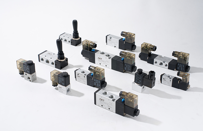
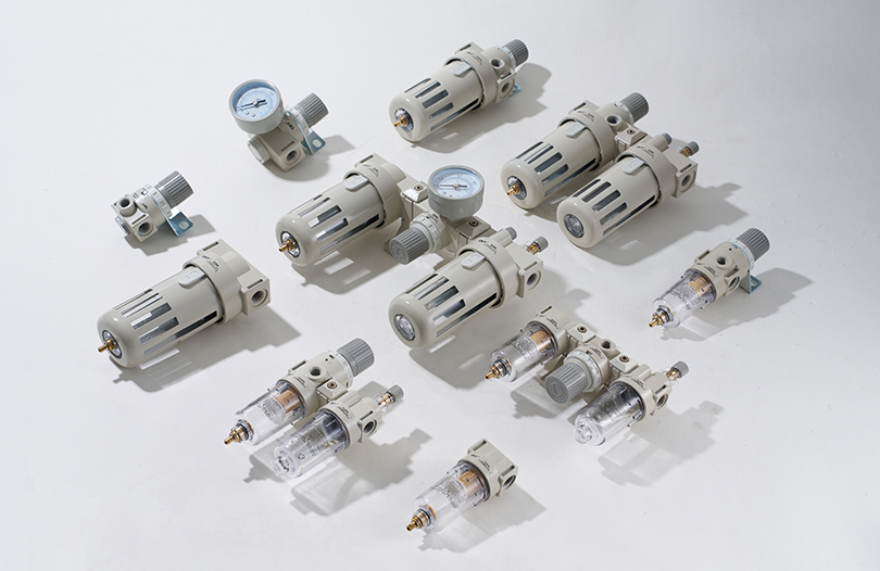
- No supply pressure — check upstream solenoid valve function and FRL unit
- Piston rod seized — caused by lack of lubrication or severe rod bushing wear
- External mechanical obstruction — load is jammed or cylinder is mechanically blocked at end of stroke
- Cushion needle valve closed too far — cylinder stalls before reaching the end cap due to trapped exhaust pressure
Cylinder moves erratically or with jerky motion
- Stick-slip from dry seals — add lubrication or upgrade to a pre-lubricated cylinder model
- Contaminated air supply — particulates or water in the air supply cause uneven friction. Inspect and service the air filter and water separator.
- Undersized flow control valves — insufficient flow causes hunting behavior. Review the flow rate requirements against the installed valve Cv rating.
Cylinder fails to reach end of stroke under load
- Operating pressure too low — verify regulator setpoint and check for pressure drop in long supply lines
- Bore size undersized for the load — recalculate required force using F = P × A and upgrade bore if needed
- Severe piston seal bypass — the cylinder cannot build full chamber pressure because air is crossing the piston faster than it's being supplied
Rapid and repeated seal failure
- Contaminated supply air — particles as small as 10 microns act as an abrasive against seal lips. Install a 5-micron coalescing filter upstream.
- Scored rod surface — a damaged rod destroys new seals within days. The rod must be corrected before seal replacement makes any difference.
- Misaligned cylinder — side loading damages seal lips unevenly. Fix alignment before resealing.
- Wrong seal material for the environment — upgrade seal material to match actual operating temperature and chemical exposure.
When to Replace the Entire Air Cylinder vs. Repair It
Not every cylinder problem requires a full replacement. Seal kits for standard ISO cylinder sizes are widely available and inexpensive — replacing seals in a 63mm bore cylinder typically costs under $20 in parts, versus $80–$250 for a new equivalent cylinder. But seal replacement is only worthwhile if the other components are still in serviceable condition.
Repair is the right choice when:
- The barrel bore is smooth and within tolerance (no scoring or corrosion)
- The piston rod is straight and its surface finish is intact
- The end caps are crack-free and threads are in good condition
- The cylinder has not exceeded approximately 50% of its expected service life
- An identical replacement part is on long lead time and production cannot wait
Replace the cylinder when:
- The barrel bore is scored or corroded — new seals will fail rapidly against a damaged bore surface
- The rod is bent, deeply scored, or below minimum diameter — rods cannot be reliably repaired in the field
- End cap threads are stripped or end caps are cracked
- The cylinder has been repaired multiple times and is still failing within short intervals — a pattern of repeated failure signals a systemic problem (wrong cylinder for the application) that repair will not solve
- The cylinder is a non-standard or obsolete size where seal kits are no longer available
Before ordering a replacement, document the existing cylinder's specifications completely: bore diameter, stroke length, mounting style (tie rod, profile body, or round body), port size and location, rod end thread type, and any special features (stainless steel, magnetic piston, cleanroom specification). Ordering a cylinder with the wrong port position or rod end type will require additional mechanical modification and delay the repair further.