
Content
- 1 What an Air Cylinder Does — The Short Answer
- 2 How an Air Cylinder Works Internally
- 3 Types of Air Cylinders and What Each One Does
- 4 Where Air Cylinders Are Used — Real-World Applications
- 5 How to Calculate the Force an Air Cylinder Produces
- 6 Air Cylinder vs. Hydraulic Cylinder vs. Electric Actuator
- 7 Key Specifications to Understand When Selecting a Pneumatic Cylinder
- 8 Common Problems with Air Cylinders and How to Fix Them
- 9 How to Extend Air Cylinder Service Life
- 10 ISO Standards Governing Air Cylinders
What an Air Cylinder Does — The Short Answer
An air cylinder — also called a pneumatic cylinder — converts compressed air energy into linear mechanical motion. When pressurized air enters one side of the cylinder, it pushes a piston along a sealed bore, generating a controlled push or pull force. That force moves a load, clamps a part, lifts a workpiece, actuates a valve, or performs dozens of other mechanical tasks in industrial, automotive, and manufacturing environments.
In practical terms: you supply air at a set pressure, and the cylinder delivers a precise, repeatable stroke. Most standard air cylinders operate between 40 and 150 PSI (2.8 to 10.3 bar), producing forces that range from a few newtons in miniature cylinders to tens of thousands of newtons in large-bore industrial units. A 100 mm bore cylinder at 6 bar, for example, produces roughly 4,712 N (about 1,060 lbf) of thrust — enough to press-fit a bearing, stamp a label, or advance a conveyor gate in under a second.
The key advantage over hydraulic or electric actuators is simplicity: air is clean, compressible, and available in virtually every factory. Pneumatic actuators require no return lines for fluid, generate no heat buildup from motors, and can be cycled millions of times without significant wear when properly maintained.
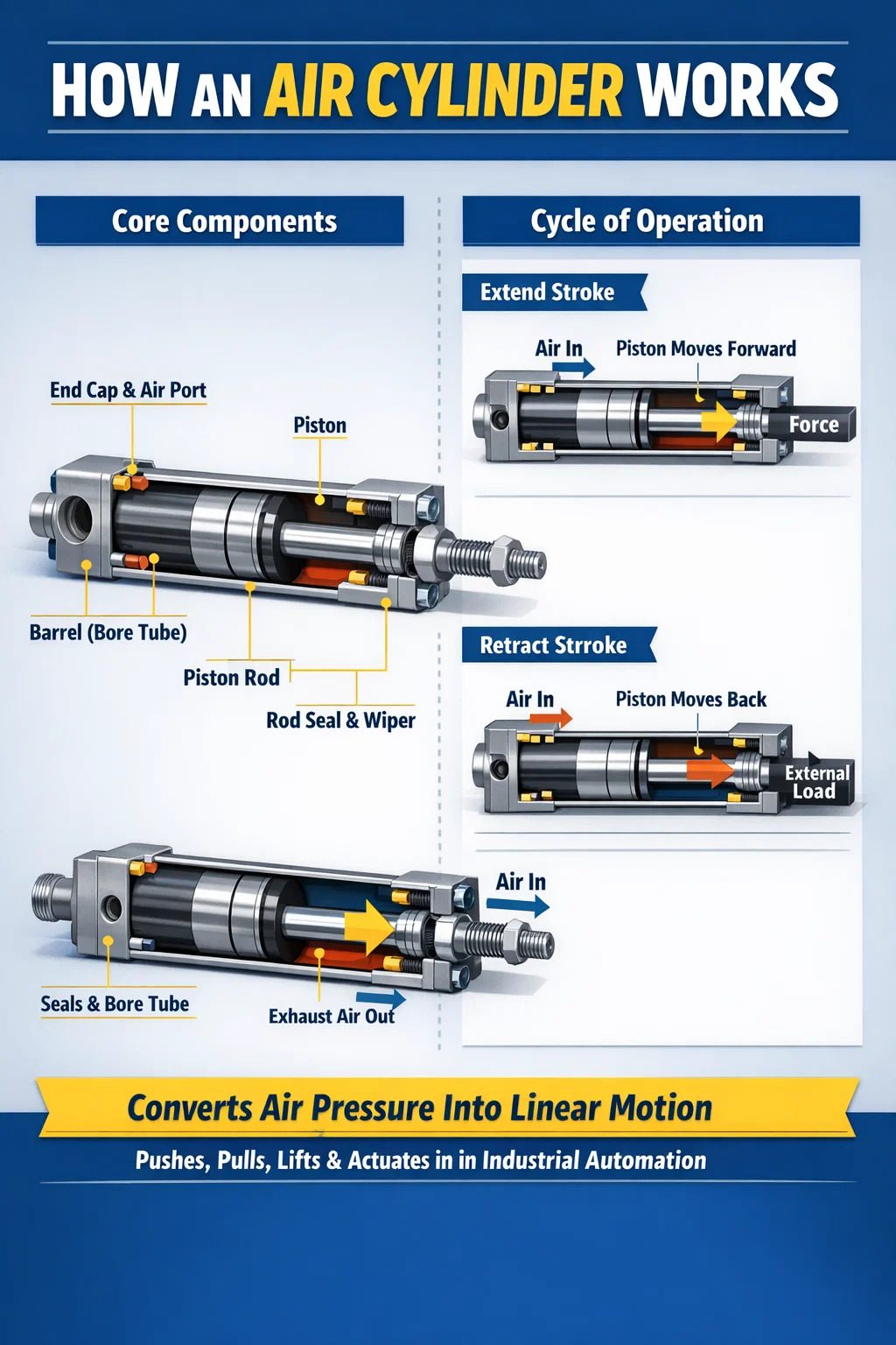
How an Air Cylinder Works Internally
Understanding the internal mechanics helps when selecting, sizing, or troubleshooting a pneumatic cylinder. Every air cylinder shares the same fundamental architecture, even when the outer shape varies.
Core Components
- Barrel (bore tube): The cylindrical housing, typically made from aluminum alloy, stainless steel, or hard-anodized aluminum. Bore diameter directly determines output force.
- Piston: A disc that slides inside the bore, sealed by O-rings or lip seals to prevent air from bypassing.
- Piston rod: A hardened, chrome-plated steel rod attached to the piston, transmitting force to the external load.
- End caps (heads): Seal both ends of the barrel and contain the air inlet/outlet ports.
- Rod seal and wiper: Prevent air leakage along the rod and keep contaminants out of the bore.
- Cushion adjusters: Optional needle valves built into the end caps that decelerate the piston near end-of-stroke, reducing impact noise and wear.
The Cycle of Motion
When a solenoid valve opens, compressed air flows into the cylinder's cap-end port. Air pressure builds against the piston face. Force equals pressure multiplied by the effective piston area (F = P × A). As force overcomes friction and load resistance, the piston advances — extending the rod. To retract, the valve switches: air enters the rod-end port, pressure acts on the annular area of the piston (full area minus rod cross-section), and the rod pulls back. Exhausted air exits through a muffler to reduce noise.
This complete cycle — extend and retract — can happen in fractions of a second. High-speed pneumatic cylinders used in packaging lines commonly complete 5 to 10 full cycles per second. In robotic pick-and-place cells, cycle times of 200 to 300 milliseconds per stroke are standard.
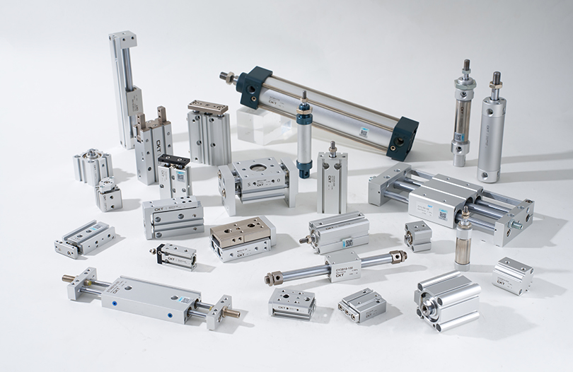
Types of Air Cylinders and What Each One Does
Not all pneumatic cylinders perform the same function or suit every application. The design of the cylinder determines how it moves, how much force it applies, and in what direction it acts. Below is a breakdown of the most common types.
| Type | How It Acts | Retraction Method | Best For |
|---|---|---|---|
| Single-Acting | Air extends only | Internal spring | Clamping, stamping, fail-safe valves |
| Double-Acting | Air extends and retracts | Air pressure | Most industrial automation tasks |
| Rodless | Carriage moves along barrel | Air pressure (both directions) | Long strokes, space-limited layouts |
| Telescoping | Multiple nested stages extend sequentially | Spring or air | Dump trucks, lifts, tight retracted length |
| Rotary | Converts air to rotary motion (limited angle) | Air pressure | Indexing, turning, part orientation |
| Tandem | Two pistons on one rod, additive force | Air pressure | High-force applications with small bore |
| Guided (non-rotating) | Rod guided by external rails or twin-rod design | Air pressure | Precision positioning, side-load resistance |
Single-Acting vs. Double-Acting: Which Does More Work?
Single-acting pneumatic cylinders use air pressure in only one direction; a return spring brings the rod back. They consume roughly half the air of double-acting units, which makes them attractive for simple clamping tasks where only the extend stroke needs power. However, the spring takes up internal space, reduces effective stroke length by 10–20%, and the spring force works against the piston on extension — lowering net output force.
Double-acting air cylinders use compressed air for both extending and retracting strokes. This is the most common type in industrial automation, accounting for the majority of pneumatic actuator installations worldwide. They deliver full controllable force in both directions, allow precise speed control with flow restrictors on each port, and have no spring rate to account for in force calculations.
Where Air Cylinders Are Used — Real-World Applications
Pneumatic cylinders appear in virtually every sector of manufacturing and many areas of everyday infrastructure. Their speed, cleanliness, and cost-effectiveness make them the dominant linear actuator in light-to-medium force applications.
Manufacturing and Assembly Lines
This is the largest single application area for air cylinders. On automotive assembly lines, pneumatic actuators perform tasks including part transfer, part clamping during welding, door hinge pressing, and screwdriving fixture positioning. A single vehicle body-in-white assembly station may use 50 to 200 individual pneumatic cylinders working in synchronized sequences. Bore sizes typically range from 32 mm to 125 mm, with strokes from 25 mm to 400 mm depending on the task.
Food and Beverage Processing
Food processing demands actuators that can be washed down with caustic cleaning agents and resist contamination. Stainless steel air cylinders with FDA-compliant seals and no external lubrication ports are standard in bottling plants, bakery lines, and meat processing facilities. Air cylinders here sort products on conveyors, actuate filling nozzles, and operate packaging machinery — completing thousands of cycles per hour in high-humidity environments.
Packaging Machinery
Cartoning machines, form-fill-seal machines, and case erectors rely heavily on pneumatic cylinders for flap folding, product pushing, and box forming. The high cycle rate — some packaging lines run at 400 to 600 packs per minute — demands actuators with near-instant response and long service life. Compact profile cylinders (ISO 21287 series) are particularly common here, saving space in crowded machine frames.
Material Handling and Conveying
Air cylinders divert products at conveyor junctions, raise and lower stop gates, and actuate pallet lifts in warehousing operations. Rodless pneumatic cylinders are especially valuable in these settings because they provide long strokes — up to 6,000 mm in some catalog models — without the space penalty of an extended rod.
Automotive Service Equipment
Vehicle lifts, tire changers, and brake lathes all rely on pneumatic actuators. Air-over-oil systems in body shops combine the speed of pneumatics with the incompressibility of hydraulics, using an air cylinder to push hydraulic fluid for precise press operations — applying up to 20 tons of force from a shop air supply.
Medical and Laboratory Equipment
Miniature air cylinders with bores as small as 6 mm are used in diagnostic equipment, sample handling robots, and hospital beds. These cylinders use clean dry air or nitrogen, making them compatible with sterile environments. Their low weight and vibration-free operation are critical in precision lab instrumentation.
Construction and Heavy Equipment
Although heavy machinery more often uses hydraulic cylinders for their higher force density, pneumatic cylinders still appear in air braking systems, door actuation on buses and trains, and pneumatic jack hammers. Telescoping air cylinders lift dump truck beds and operate platform hoists where exact intermediate positioning is not required.
How to Calculate the Force an Air Cylinder Produces
Sizing a pneumatic cylinder correctly requires calculating two force values: the extend force (acting on the full piston face) and the retract force (acting on the piston's annular area, which is reduced by the rod cross-section).
Extend Force Formula
F_extend = P × (π/4) × D²
Where P is supply pressure in Pascals (1 bar = 100,000 Pa) and D is bore diameter in meters.
Retract Force Formula
F_retract = P × (π/4) × (D² − d²)
Where d is the rod diameter. For a 63 mm bore cylinder with a 20 mm rod running at 6 bar:
- Extend force: 600,000 × (π/4) × 0.063² ≈ 1,870 N
- Retract force: 600,000 × (π/4) × (0.063² − 0.020²) ≈ 1,681 N
In practice, actual output force is 10–20% lower than theoretical because of seal friction and back-pressure in the exhaust line. Engineers typically apply an efficiency factor of 0.8 to 0.9 when calculating effective cylinder force for load sizing.
Always select a cylinder that provides at least 25–50% more theoretical force than the required load to ensure reliable actuation across the full pressure and temperature operating range.
Air Cylinder vs. Hydraulic Cylinder vs. Electric Actuator
Choosing between pneumatic, hydraulic, and electric linear actuators depends on force requirements, precision needs, duty cycle, and environmental conditions. Each technology excels in different scenarios.
| Criterion | Air Cylinder | Hydraulic Cylinder | Electric Actuator |
|---|---|---|---|
| Typical force range | 10 N – 100 kN | 1 kN – 10 MN | 10 N – 50 kN |
| Speed | Very fast (up to 3 m/s) | Moderate (up to 0.5 m/s) | Moderate (up to 1 m/s) |
| Positional accuracy | Low (end stops only) | Medium (with servo) | High (±0.01 mm possible) |
| Energy efficiency | Low (25–35%) | Low–Medium (60–75%) | High (85–95%) |
| Initial cost | Low | Medium–High | High |
| Maintenance | Low | High (fluid changes, leaks) | Low–Medium |
| Cleanroom / food safe | Yes (with correct seals) | Difficult (oil risk) | Yes |
The takeaway: air cylinders win on speed, simplicity, and upfront cost. Hydraulic cylinders dominate where massive force is required in a compact package. Electric actuators lead when mid-stroke positioning accuracy or energy recovery matters. Many modern factories use all three technologies in the same facility, each matched to the task it handles best.
Key Specifications to Understand When Selecting a Pneumatic Cylinder
Purchasing the wrong cylinder — even slightly undersized — can lead to failed cycles, premature seal wear, machine downtime, and costly production losses. Understanding the following specifications prevents most selection errors.
Bore Diameter
Bore is the internal diameter of the cylinder barrel and is the primary determinant of output force. Standard bore sizes follow ISO 15552 or NFPA T3.6.7 series: 12, 16, 20, 25, 32, 40, 50, 63, 80, 100, 125, 160, 200, 250, and 320 mm are common increments. Doubling the bore quadruples the force at the same pressure, since force scales with area (A = πD²/4).
Stroke Length
Stroke is the total distance the piston rod travels between fully retracted and fully extended. Longer strokes increase the risk of rod buckling under compressive loads. Most manufacturers provide column strength charts to determine the maximum allowable thrust load for a given stroke and rod diameter. For strokes exceeding approximately 10 times the bore diameter, guided cylinders or external support become necessary.
Operating Pressure Range
Most pneumatic cylinders are rated for 1 to 10 bar (14.5 to 145 PSI). The minimum operating pressure — typically 1 to 2 bar — is critical: cylinders sized to work at 4 bar may stall or cycle erratically if plant air pressure drops during peak demand. Always verify the air supply's regulated minimum pressure at the cylinder inlet, not just at the compressor output.
Mounting Style
Mounting determines how the cylinder transmits force to the machine frame and how it handles misalignment. Common mounting styles include:
- Foot mount (FB): Bolts to a flat surface; rigid, good for pure axial loads.
- Flange mount (FA/FF): Bolted at cap or rod end; very rigid, high load capacity.
- Clevis mount (CB/CA): Allows the cylinder to pivot; needed when the load path has angular movement.
- Trunnion mount (MT): Pivots on a central pin; used in presses and linkage mechanisms.
Rigid mounts (foot and flange) should only be used when the load is perfectly aligned with the rod axis. Any angular misalignment with a rigid mount creates side loading on the piston rod, accelerating rod seal wear and potentially bending the rod over time.
Cushioning
When a piston reaches end-of-stroke at high speed, it impacts the end cap. Without cushioning, this creates shock loads that damage the cylinder, the machine frame, and any attached tooling. Built-in cushion adjusters trap a pocket of air ahead of the piston near end-of-stroke, creating a pneumatic dashpot effect. At piston speeds above 300 mm/s, cushioning should be considered standard rather than optional.
Seal Material and Temperature Rating
Standard NBR (nitrile) seals cover −20°C to +80°C and are adequate for most factory environments. High-temperature applications (paint ovens, foundries) require FKM (Viton) seals rated to +200°C. Low-temperature or food-safe applications may call for EPDM seals or PTFE-coated components. Using the wrong seal material is a frequent cause of premature cylinder failure.
Common Problems with Air Cylinders and How to Fix Them
Even well-selected pneumatic cylinders develop faults over time. Recognizing the symptoms early saves significant downtime and repair costs.
Cylinder Drifting or Failing to Hold Position
If a loaded cylinder slowly drifts from its extended position when the valve closes, the piston seal is leaking air past the piston face. This is one of the most common air cylinder failure modes. The fix involves replacing the piston O-rings or lip seals. Before doing so, check whether the cylinder has been operated above its rated pressure, which accelerates seal extrusion into clearance gaps.
External Air Leaks at the Rod
A hissing sound or visible air stream around the rod seal indicates rod seal wear or rod surface damage. Chrome-plated rods can develop corrosion pits or scoring if the wiper seal fails and allows contaminants to enter. A pitted rod cuts through new seals quickly — the rod itself must be inspected and often replaced. In harsh environments, consider stainless steel rods with ceramic coating for significantly longer service life.
Slow or Sluggish Stroke
If a cylinder completes its stroke more slowly than expected, check in this order: supply pressure at the cylinder port (confirm no pressure drop in lines), flow control valves (may be set too restrictively), airline filter bowl (clogged filter reduces flow), and cylinder bore (internal corrosion or contamination increases seal friction). A partially closed exhaust flow control is the single most common cause of slow extension in field installations.
Cylinder Won't Extend Under Load
When a cylinder moves freely with no load but stalls under the application load, the bore size is inadequate for the required force. Recalculate using F = P × A, accounting for friction and back-pressure. The solution is either to increase bore size, increase supply pressure (within safe limits), or reduce the load demand. Never simply crank up pressure beyond the cylinder's rated maximum — this damages seals and can rupture end caps.
Premature Seal Wear
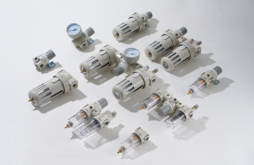
Seals that need replacement after only a few months of service — rather than the expected millions of cycles — usually fail for one of three reasons: contaminated air supply (abrasive particles scoring the bore and seals), side loading on the rod (from misalignment), or inadequate lubrication. Use an FRL (filter-regulator-lubricator) unit on every pneumatic supply line. For oil-free cylinders with PTFE seals, ensure the air is clean and dry rather than adding mist lubricant, which degrades PTFE.
How to Extend Air Cylinder Service Life
A well-maintained air cylinder in a clean industrial environment should last 50 to 100 million cycles before needing a seal kit replacement. Reaching that service life requires attention to the entire pneumatic circuit, not just the cylinder itself.
- Filter air to 5 microns or better. Particulate contamination is the leading cause of accelerated bore and seal wear. A 40-micron standard filter is insufficient for cylinder protection.
- Regulate supply pressure to the lowest effective level. Running at 6 bar when 4 bar achieves the required force wastes energy and increases seal stress. Every 1 bar of excess pressure reduces seal life measurably.
- Install cushioning on all high-speed applications. End-of-stroke impact with no cushion can generate instantaneous shock forces 5 to 10 times the operating force, cracking end caps and deforming pistons.
- Align the cylinder rod precisely with the load path. Even 1–2 degrees of angular misalignment creates continuous side loading that wears rod seals 3 to 5 times faster than in a correctly aligned installation.
- Use a dryer or aftercooler on the compressor output. Condensed water in the air line causes internal corrosion of uncoated aluminum bores and degrades lubricant films on seals.
- Schedule periodic inspection of rod condition. Visually check the rod for pitting, scoring, or corrosion every three to six months in normal environments, monthly in harsh conditions.
ISO Standards Governing Air Cylinders
Standardization ensures that cylinders from different manufacturers are dimensionally interchangeable, making replacement and multi-source procurement straightforward. The primary standards are:
- ISO 15552: The main international standard for round and square profile pneumatic cylinders (the former ISO 6431 and VDMA 24562). Specifies bore sizes, port threads, mounting dimensions, and rod end threads. This is the standard for most medium and large industrial cylinders worldwide.
- ISO 21287: Compact cylinders with limited mounting space requirements. Common in packaging and food machinery where machine envelopes are tight.
- ISO 6432: Miniature cylinders from 8 to 25 mm bore, used in instrumentation and light assembly tasks.
- NFPA T3.6.7: The North American (NFPA) standard governing tie-rod cylinders common in North American industrial machinery. Bore sizes and mounting patterns differ from ISO 15552, so confirm the applicable standard before replacement purchasing.
Specifying an ISO-standard air cylinder means any manufacturer's compliant product will bolt in as a drop-in replacement — a significant advantage in global supply chains where preferred brands may have long lead times.