
Content
- 1 What Is an Air Cylinder?
- 2 How an Air Cylinder Works: The Core Mechanics
- 3 Types of Air Cylinders and Their Differences
- 4 Key Components Inside a Pneumatic Cylinder
- 5 Key Specifications to Understand When Selecting an Air Cylinder
- 6 Where Air Cylinders Are Used: Real-World Applications
- 7 Air Cylinders vs. Hydraulic Cylinders vs. Electric Actuators
- 8 The Pneumatic Circuit: How Air Cylinders Connect to a System
- 9 Common Problems With Air Cylinders and How to Diagnose Them
- 10 Maintenance Best Practices for Pneumatic Cylinders
- 11 Innovations and Trends in Pneumatic Cylinder Technology
What Is an Air Cylinder?
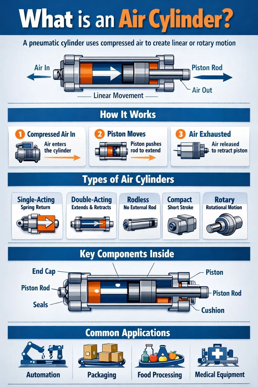
An air cylinder — also called a pneumatic cylinder — is a mechanical device that uses compressed air to produce linear or rotary motion and force. It converts the potential energy stored in pressurized air into controlled mechanical work. In simpler terms: you push compressed air in, and the cylinder pushes something — a clamp, a press, a valve, a door — with a precise, repeatable amount of force.
Air cylinders are among the most widely used actuators in industrial automation. They appear in assembly lines, packaging machinery, automotive manufacturing, food processing, medical equipment, and countless other systems. Their popularity comes from a combination of simplicity, low cost, high speed, and inherent cleanliness compared to hydraulic alternatives.
A standard pneumatic cylinder consists of a cylindrical barrel, a piston, a piston rod, end caps, seals, and ports for air entry and exit. When compressed air — typically at 60 to 120 PSI (4 to 8 bar) in most industrial settings — enters one side of the piston, it creates a pressure differential that drives the piston and its attached rod in one direction. Releasing or redirecting air reverses or retracts the motion.
This fundamental mechanism has remained largely unchanged for over a century, yet modern manufacturing has refined air cylinders to operate with tolerances measured in micrometers, cycle lifetimes exceeding 20 million strokes, and response times as fast as a few milliseconds.
How an Air Cylinder Works: The Core Mechanics
Understanding how a pneumatic cylinder operates requires looking at pressure, area, and force together. The output force a cylinder produces is determined by a straightforward formula:
Force (F) = Pressure (P) × Area (A)
For example, a cylinder with a bore diameter of 50 mm has a piston area of approximately 19.6 cm². At a supply pressure of 6 bar (87 PSI), it produces a theoretical push force of roughly 1,178 Newtons (about 265 lbf). Real-world force is slightly less due to friction and seal resistance, typically around 80–90% of the theoretical value.
Step-by-Step Operation
- A compressor generates and stores compressed air in a reservoir tank.
- A directional control valve (commonly a 4/2 or 5/2 valve) directs air to the appropriate port on the cylinder.
- Compressed air enters the cylinder chamber and pushes against the piston face.
- The piston moves, driving the rod outward (extension stroke).
- The valve switches, sending air to the opposite side and exhausting the first chamber.
- The piston retracts back to its starting position.
Speed is controlled by flow control valves (also called needle valves or throttle valves), which restrict how quickly air can enter or exhaust from the cylinder chamber. Cushioning features built into the end caps slow the piston near the end of the stroke to prevent impact damage — an important consideration when loads are heavy or strokes are long.
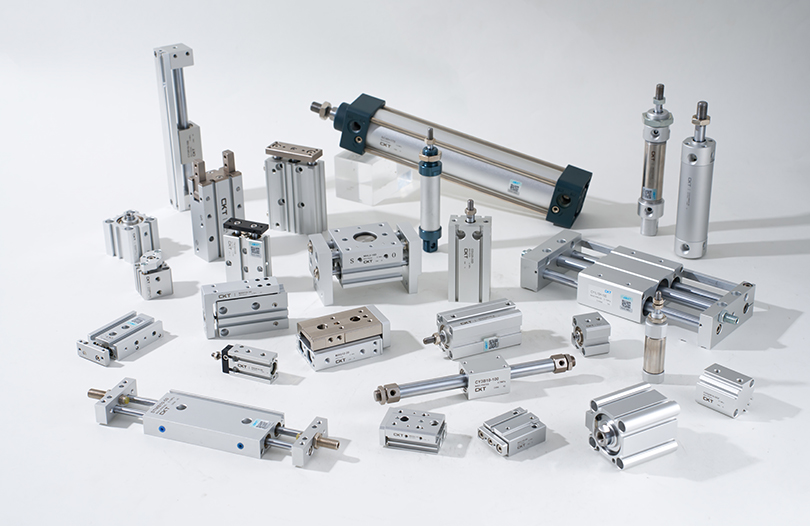
Types of Air Cylinders and Their Differences
Not all pneumatic cylinders are the same. The type selected for any application depends on the required motion, available space, load characteristics, and environmental conditions. Here are the most commonly used categories:
Single-Acting Cylinders
A single-acting cylinder uses compressed air to move the piston in only one direction. Return movement is accomplished by an internal spring or an external load (gravity, for example). These cylinders have just one air port. They are simpler, use less air per cycle, and are ideal for clamping, stamping, and holding applications where the working force is only needed in one direction. Common bore sizes range from 8 mm to 100 mm, with stroke lengths typically up to 200 mm due to spring limitations.
Double-Acting Cylinders
The most widely used type in industrial automation. A double-acting cylinder uses compressed air for both the extension and retraction strokes. Two air ports — one on each side of the piston — allow independent control of each direction. This provides powered force in both directions, making it suitable for pushing, pulling, lifting, pressing, and any application requiring active control of the return stroke. Bore sizes can range from 6 mm to over 500 mm, and strokes can extend to several meters in specialized designs.
Rodless Cylinders
Instead of a conventional piston rod extending from one end, a rodless cylinder transmits motion through a mechanical or magnetic coupling along the outside of the cylinder barrel. This design requires roughly half the installation length of a conventional cylinder for the same stroke, making it valuable in tight spaces. Rodless cylinders are common in pick-and-place systems, gantry automation, and slide tables.
Compact and Short-Stroke Cylinders
Also called flat cylinders or pancake cylinders, these are designed for very short strokes — often 1 mm to 50 mm — in constrained spaces. Their low-profile form factor makes them a favorite in electronics manufacturing, PCB handling, and medical device assembly where space is at a premium.
Rotary Actuators
While most people associate air cylinders with linear motion, rotary pneumatic actuators convert compressed air into angular movement. They are used to rotate valves, position parts, or drive index tables. Common rotation angles are 90°, 180°, and 270°, though continuous rotation versions also exist.
Tandem Cylinders
Two cylinders connected in series sharing the same piston rod. This configuration roughly doubles the output force without increasing the bore diameter — useful when high force is needed but the installation diameter is restricted.
Multi-Position Cylinders
Standard cylinders offer two positions: fully extended and fully retracted. Multi-position (or multi-stage) cylinders combine two or more cylinders to achieve three or four discrete positions along the stroke. This is useful for indexing, part positioning, and assembly operations requiring multiple stop points without servo control.
| Type | Motion Direction | Typical Stroke | Primary Use |
|---|---|---|---|
| Single-Acting | One direction (spring return) | Up to 200 mm | Clamping, holding |
| Double-Acting | Both directions | Up to several meters | General automation |
| Rodless | Linear (no external rod) | Up to 10 m+ | Long-travel transport |
| Compact | Linear | 1–50 mm | Space-constrained tasks |
| Rotary Actuator | Rotational | 90°–270° | Valve operation, indexing |
Key Components Inside a Pneumatic Cylinder
Every air cylinder — regardless of type or size — is built from several critical components. Understanding these parts helps when specifying, maintaining, or troubleshooting a cylinder in the field.
- Barrel (Cylinder Tube): The main body that contains the piston and guides its travel. Usually made from aluminum alloy, stainless steel, or carbon steel tubing with a precision-honed inner surface. Surface roughness is typically held to Ra 0.4–0.8 µm to minimize seal wear.
- Piston: The disc-shaped component that separates the two air chambers inside the barrel. It transfers pneumatic pressure into mechanical force on the rod. Pistons carry O-ring or lip seals to prevent air leakage between chambers.
- Piston Rod: A precision-ground steel shaft (often chrome-plated or hard-anodized) attached to the piston and extending through one or both end caps. Rod diameter is sized to resist buckling under compressive load — typically using Euler's column buckling formula for longer strokes.
- End Caps (Head and Cap): Close the two ends of the barrel. The rod-side end cap (head) contains the rod seal and wiper seal. The blind-side end cap (cap) may include cushion valves and air ports.
- Seals: Perhaps the most maintenance-critical components. Piston seals prevent cross-chamber leakage; rod seals prevent external leakage; wiper seals (also called scraper seals) exclude dust and contaminants from entering. Common seal materials include NBR (nitrile), Polyurethane, PTFE, and Viton — each suited to different temperature ranges and media.
- Cushion Valves: Adjustable needle valves built into the end caps that trap a small air pocket ahead of the piston near stroke end, decelerating it gradually. Without cushioning, cylinders operating at high speed with heavy loads can generate impact forces exceeding 10 kN, causing premature wear or structural damage.
- Rod Bearing (Bushing): A low-friction bearing surface in the head end cap that guides the rod and absorbs side loads. Often made from sintered bronze or IGUS-type self-lubricating polymer.
- Position Sensors / Magnetic Switches: Many cylinders include an external groove for mounting reed switches or Hall-effect sensors that detect a magnet embedded in the piston. These provide position feedback — fully extended or fully retracted signals — without any penetration of the cylinder body.
Key Specifications to Understand When Selecting an Air Cylinder
Choosing the right pneumatic cylinder for an application is more nuanced than it first appears. Getting the specification wrong can result in insufficient force, premature seal failure, rod buckling, or poor cycle times. Here are the parameters that matter most:
Bore Diameter
The internal diameter of the barrel. This is the primary determinant of output force. Standard bore sizes follow ISO 6432 (for bore diameters 8–25 mm) and ISO 15552 (for 32–320 mm). Common sizes include 12, 16, 20, 25, 32, 40, 50, 63, 80, 100, 125, 160, and 200 mm. A larger bore means more force at the same pressure but also more air consumption per cycle.
Stroke Length
The total travel distance of the piston rod from fully retracted to fully extended. Standard strokes are often available in 25 mm increments, though custom lengths are common. Longer strokes increase the risk of rod buckling and require checking the cylinder's buckling load rating against the applied compressive force.
Operating Pressure
Most industrial pneumatic cylinders are rated for 1 to 10 bar (14.5 to 145 PSI) working pressure. The most common plant air supply is 6–7 bar. Always confirm the maximum operating pressure rating of a cylinder before installation — exceeding it can rupture seals or deform end caps.
Rod Diameter and Buckling Resistance
For compression (push) loads, the rod must be checked for buckling, especially on long strokes. The safe compressive load depends on the rod diameter, free buckling length, and mounting configuration. A cylinder with a 20 mm rod at 800 mm free length may only safely handle 3–4 kN in compression — significantly less than its theoretical piston force.
Operating Temperature
Standard cylinders with NBR seals operate between -20°C and +80°C. For higher temperatures (up to 200°C), Viton or PTFE seals are required. Food-grade and cleanroom variants use special materials and surface treatments to meet sanitary and contamination standards.
Mounting Style
How a cylinder is mounted to a machine frame has significant implications for load distribution and alignment. Common mounting styles include:
- Foot/flange mount: Rigid, fixed mounting. Best for pure linear loads with no angular variation.
- Clevis mount (rear pivot): Allows the cylinder to pivot, accommodating loads that change angle during the stroke.
- Trunnion mount: Pivots from the side, suitable for heavy-duty applications with significant angular movement.
- Rod end attachments: Spherical rod eyes or clevis rod ends at the tip allow angular alignment at the load connection point.
Where Air Cylinders Are Used: Real-World Applications
Pneumatic cylinders appear in virtually every industry that involves automated movement. Their speed, simplicity, and cleanliness (exhaust air is just air, not oil) make them the actuator of choice in countless environments.
Manufacturing and Assembly Automation
In automotive plants, pneumatic cylinders drive robotic welding fixtures, part clamps, press-fit tools, and conveyor diverters. A single assembly line may contain hundreds to thousands of air cylinders operating at cycle rates of 30 to 120 cycles per minute. The repeatability of pneumatic positioning — with hardstop end positions — makes them reliable for high-volume production.
Packaging Machinery
Filling machines, capping heads, label applicators, carton erectors, and case sealers all depend on pneumatic cylinders for rapid, repeatable motion. A bottling line running at 600 bottles per minute will cycle its filling cylinder 10 times per second — placing extreme demands on seal life and valve response time.
Food and Beverage Processing
Stainless steel cylinders with FDA-compliant seals are used in meat portioning, bakery machinery, dairy processing, and vegetable sorting. The ability to wash down equipment with water and cleaning agents without damaging the actuator is a critical advantage over hydraulic alternatives in this environment.
Medical and Pharmaceutical Equipment
Clean-room compatible cylinders made from anodized aluminum or stainless steel with low-outgassing seals appear in tablet press machines, syringe filling equipment, and diagnostic analyzers. These cylinders must meet stringent contamination standards and often operate with instrument-quality air filtered to 0.01 µm.
Construction and Heavy Equipment
While large construction machinery primarily uses hydraulic cylinders for their superior force-to-size ratio, pneumatic cylinders appear in air brakes for trucks and trains, pneumatic hammers, riveting tools, and door operating mechanisms. Compressed air at 8–10 bar can generate braking forces sufficient to stop a 40-tonne articulated truck reliably in wet and dusty conditions.
Printing and Paper Handling
Web offset presses, sheet-fed presses, and paper converting machines use pneumatic cylinders for nip roll adjustment, impression throw-on/off, ink fountain control, and gripper mechanisms. The speed of pneumatic actuation matches the high running speeds of modern presses — some operating at over 15,000 sheets per hour.
Agricultural Machinery
Planters, sprayers, and harvesting equipment use air cylinders for seed metering shutoffs, spray boom folding, and tailgate control. Robustness in outdoor environments with dust, mud, and temperature swings from -30°C in winter storage to +50°C in summer field operation is a key requirement for agricultural pneumatic components.
Air Cylinders vs. Hydraulic Cylinders vs. Electric Actuators
When engineers select an actuator type, they compare pneumatic cylinders against two main alternatives: hydraulic cylinders and electric actuators (servo or stepper-driven linear stages). Each technology has a distinct sweet spot.
| Factor | Air Cylinder | Hydraulic Cylinder | Electric Actuator |
|---|---|---|---|
| Force Range | Low to medium (up to ~50 kN) | Very high (100 kN to MN range) | Low to high (varies widely) |
| Speed | Very fast (up to 10 m/s) | Moderate (up to ~0.5 m/s) | Moderate to fast |
| Position Control | End positions only (normally) | Good with servo valve | Excellent (full stroke) |
| Energy Efficiency | Low (5–15% overall) | Medium (60–75%) | High (85–95%) |
| Initial Cost | Low | Medium to high | High |
| Cleanliness | Excellent (exhaust is air) | Poor (oil leakage risk) | Excellent |
| Maintenance | Low | High (fluid, filters, seals) | Low to medium |
The energy efficiency of pneumatic systems — often cited at around 10–15% overall when accounting for compressor inefficiency, distribution losses, and exhaust losses — is their most significant weakness in the context of modern energy-conscious manufacturing. However, the low unit cost, reliability, and the widespread availability of plant compressed air infrastructure continue to make pneumatic cylinders the practical default for high-speed, moderate-force applications.
Electric actuators are increasingly competitive for applications requiring precise intermediate positioning, force control, or programmable motion profiles — capabilities that standard pneumatic cylinders cannot match without adding proportional valves and feedback sensors, which significantly increase complexity and cost.
The Pneumatic Circuit: How Air Cylinders Connect to a System
An air cylinder is only one part of a pneumatic circuit. To function correctly, it needs a properly designed system around it. Understanding the supporting components is essential for anyone specifying or maintaining pneumatic systems.
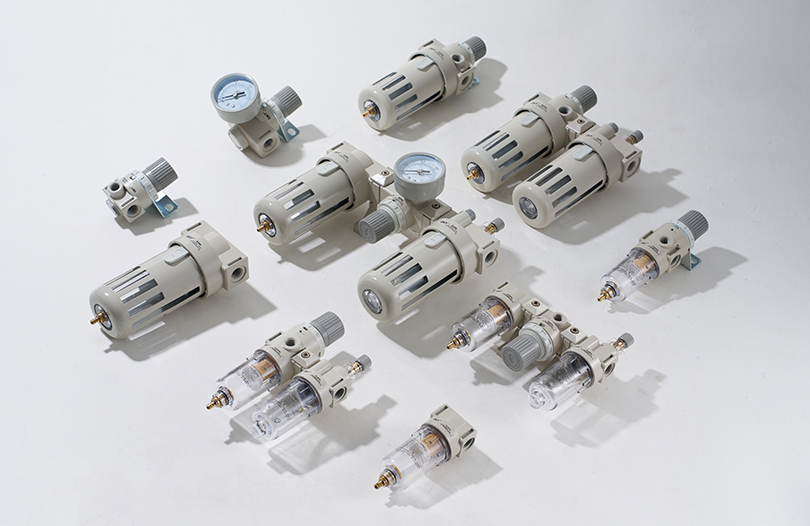
Air Preparation Unit (FRL)
The FRL unit — Filter, Regulator, Lubricator — conditions compressed air before it reaches the cylinder. The filter removes particulates and moisture; the regulator sets the working pressure; the lubricator (used less commonly today with modern self-lubricating seals) adds a fine oil mist to protect internal components. Operating a cylinder with dirty, wet, or incorrectly pressurized air is the primary cause of premature seal failure.
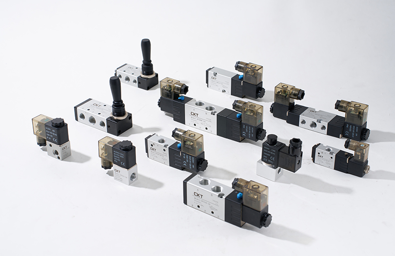
Directional Control Valves
Solenoid-operated directional valves — typically 5/2 or 5/3 way configurations — control which port of a double-acting cylinder receives supply air and which exhausts. Response times of 5–15 milliseconds are typical for standard solenoid valves. High-speed applications may use pilot-operated or poppet-type valves for faster switching.
Flow Control Valves
Meter-out flow controls are the standard approach for speed regulation in pneumatic cylinders. They restrict the exhaust flow leaving the cylinder, which creates a back-pressure that cushions and controls piston velocity. Meter-in (restricting the supply) is used in specific situations but can cause inconsistent speed with varying loads.
Pressure Regulators and Safety Valves
Individual point-of-use regulators allow different cylinders in the same system to operate at different pressures — for example, a gentle clamping force on a fragile part alongside a high-force pressing operation. Safety exhaust valves cut air supply to entire zones or machines in emergency stop situations, releasing stored energy safely.
Common Problems With Air Cylinders and How to Diagnose Them
Even well-specified and correctly installed pneumatic cylinders encounter problems over time. Knowing the most common failure modes saves diagnostic time and prevents unplanned downtime.
Air Leakage
External leakage around the piston rod or port fittings is usually detectable by sound or by applying soapy water and watching for bubbles. Internal leakage past the piston seal causes the cylinder to creep or fail to hold position under load — audible as air escaping through the exhaust port when the cylinder is commanded to hold. Seal replacement is the standard repair; replacement kits are available for most ISO-standard cylinders.
Slow or Inconsistent Movement
Sluggish cylinders are often caused by restricted flow from a blocked filter, undersized tubing, a partially closed flow control, or a worn or contaminated directional valve. Check supply pressure at the cylinder port (not just at the compressor) — significant pressure drops across long tubing runs or undersized fittings are common in plants where the distribution system has grown organically over years.
Rod Scoring and Premature Seal Wear
Side loads — forces applied perpendicular to the cylinder axis — accelerate rod bearing and seal wear. The cylinder is designed for axial loads only. If the application subjects the rod to side loading, a linear guide or external bearing should be added to carry the off-axis load. Contaminated air (particles or water) also causes abrasive wear inside the barrel.
End-of-Stroke Banging and Impact Damage
When a cylinder reaches the end of its stroke and the piston impacts the end cap with high energy, it generates shock waves, noise, and mechanical stress. Adjusting the built-in cushion valves (turning the needle clockwise to increase restriction) is the first step. If the cylinder lacks cushioning, external shock absorbers or adjustable deceleration controls can be added to the circuit.
Cylinder Fails to Move
A cylinder that doesn't move at all usually points to: no air supply (valve not switching, blocked line, closed isolator), seized piston from corrosion (common after long storage without lubrication), or a broken rod due to excessive side load or over-pressure. Systematic checking — verify pressure at the port, confirm valve switching with a solenoid indicator, then inspect the cylinder mechanically — isolates the cause quickly.
Maintenance Best Practices for Pneumatic Cylinders
Modern air cylinders are designed for minimal maintenance, but "minimal" is not the same as "zero." A structured preventive maintenance approach extends service life significantly.
- Keep air clean and dry: Drain water from the compressor tank and filters regularly. Install a refrigerated air dryer on systems in humid environments. A pressure dew point of 3°C or lower at the cylinder is a good target. Water in compressed air causes corrosion inside the barrel and swells elastomer seals.
- Inspect rod condition weekly: Scratches on the chrome rod surface damage the rod seal on every stroke. Remove sources of mechanical contact with the rod (weld spatter, misaligned fixtures) immediately and replace scored rods before they destroy the seal.
- Replace seals proactively: Many plants replace cylinder seal kits on a fixed interval — typically every 2 to 3 years on high-cycle equipment — rather than waiting for failure. Unplanned downtime on a production line typically costs far more than a seal kit and 30 minutes of labor.
- Check mounting hardware: Vibration loosens bolts, clevis pins, and rod end locknuts. A loosened pivot pin can allow a cylinder to cock sideways, generating side loads that accelerate wear. Torque check mounting hardware quarterly on high-cycle or high-vibration equipment.
- Monitor for creep or position drift: A double-acting cylinder holding a static load should not drift. Slow position changes under load indicate piston seal bypass — a warning sign of impending failure before it becomes a safety concern or quality defect.
- Keep spare cylinders or seal kits on hand: For critical production cylinders, having a complete spare unit on the shelf reduces MTTR (Mean Time to Repair) from hours to minutes. Standard ISO cylinders from stocked distributors can be sourced quickly, but custom or specialized units may have lead times of several weeks.
Innovations and Trends in Pneumatic Cylinder Technology
While the basic principle of a pneumatic cylinder has not changed, manufacturers continue to refine and extend the technology in meaningful ways.
Integrated Position Sensing and IO-Link
IO-Link-compatible sensors fitted to standard cylinders now provide continuous position feedback, diagnostics (cycle count, temperature, operating hours), and parameterization over a two-wire digital interface. This moves the pneumatic cylinder from a "dumb" actuator to an intelligent component of an Industry 4.0 architecture, enabling predictive maintenance and remote monitoring without adding dedicated wiring.
Proportional Pneumatics
Proportional pressure and flow valves, combined with position transducers, enable closed-loop force and position control of air cylinders. While not matching the precision of servo electrics, these systems can achieve positioning repeatability of ±0.1 mm and controlled force application — capabilities previously limited to hydraulic or electric actuators. Cost remains higher than simple on/off pneumatics but lower than full servo-electric systems.
Energy Recovery and Efficiency
Compressed air is expensive — generating 1 kW of mechanical work from compressed air typically costs 7–8 times more than the same work from an electric motor. This has driven development of pressure-boost systems, air-saving circuits that cut supply at mid-stroke, and recovery systems that capture exhaust energy. Some manufacturers report air savings of 30–50% in optimized circuits.
Lightweight and Corrosion-Resistant Materials
High-strength anodized aluminum, fiber-reinforced polymers, and stainless steel cylinders reduce weight — important in applications where the cylinder is mounted on a moving part — while withstanding aggressive washdown chemicals, salt spray, and outdoor exposure. Medical-grade cylinders use electropolished stainless steel throughout to eliminate potential contamination sources.
Miniaturization
Advances in precision machining and seal technology have pushed the minimum usable bore diameter of production air cylinders to 2.5 mm, with strokes as short as 1 mm. These micro-cylinders are used in medical diagnostic equipment, semiconductor handling, and micro-assembly applications where every gram and millimeter matters.