

 中文简体
 English


Content
- 1 The Component Map of a Pneumatic Cylinder
- 2 Cylinder Barrel: The Precision Tube That Determines Seal Life
- 3 End Caps: Front and Rear Covers Under Pressure
- 4 Piston: The Moving Barrier That Converts Pressure Into Force
- 5 Piston Rod: Force Transmission and Buckling Risk
- 6 Seals: Where Leakage and Friction Are Decided
- 7 Guide Rings and Rod Bearings: Stabilizers Against Side Loads
- 8 Cushioning: Absorbing Kinetic Energy Before Metal Hits Metal
- 9 Sensors: The Eyes of an Automated Cycle
- 10 Ports and Air Connections: the Gas Station of the Cylinder
- 11 Structural Variants: Tie-Rod, Round-Body, and Compact Designs
- 12 Rodless Cylinders: Same Functions Without the Rod
- 13 Failure Modes, Symptoms, and Root Causes
- 14 Using Component Knowledge When Buying a Pneumatic Cylinder
- 15 Frequently Asked Questions
- 15.1 What are the main parts of a pneumatic cylinder?
- 15.2 Which part of a pneumatic cylinder wears out first?
- 15.3 Do all pneumatic cylinders need a magnetic piston?
- 15.4 What is the difference between single-acting and double-acting cylinder parts?
- 15.5 Why is my cylinder moving slowly and jerkily?
- 15.6 Can a worn pneumatic cylinder be repaired?
A packaging line feeding a case packer starts producing crooked boxes. The maintenance engineer checks supply pressure, opens the speed-control valve, and then pulls the air cylinder off the machine. Inside, the barrel wall has a deep longitudinal scratch, the piston rod seal has a torn lip, and the piston guide ring has worn down to less than half its original thickness. That scene repeats in factories every month, and almost every time it traces back to a specific part inside the pneumatic cylinder.
A pneumatic cylinder converts compressed air into straight-line motion. It is a precision assembly in which every component controls force, speed, repeatability, or service life. Learning the parts of a pneumatic cylinder is not a theoretical exercise. It directly helps you choose a replacement model, compare supplier quotations, and find out why an automation axis suddenly turned sluggish.
Straight answer first: the three areas that matter most on any cylinder are the barrel surface treatment, the piston rod finish, and the seal system. Get those three right and the rest of the assembly will usually deliver a long, predictable working life. Get those three wrong, and no number of fancy accessories will save the unit.
The Component Map of a Pneumatic Cylinder
Regardless of brand, bore size, or design standard, nearly every pneumatic cylinder groups the same eight functional component groups: barrel, end caps, piston, piston rod, seals, guide rings and rod bearing, cushioning, and ports. Sensors and magnetic piston bands are optional but common in automation.
| Component Group | Core Function | Typical Material |
|---|---|---|
| Barrel | Guides the piston and contains pressure | Hard-anodized aluminum, stainless steel |
| End caps | Close the pressure chamber, carry ports and mounts | Die-cast aluminum, zinc alloy |
| Piston | Converts air pressure into axial force | Aluminum alloy with magnetic band option |
| Piston rod | Transfers linear force to the external load | Hard-chrome-plated steel, stainless steel |
| Seals | Block internal and external air leakage | NBR, FKM, polyurethane, PTFE |
| Guide rings and bearing | Absorb side loads and keep the stroke straight | PTFE composite, oil-impregnated bronze |
| Cushioning | Decelerates the piston before end-of-stroke impact | Adjustable needle valves, rubber bumpers, cushion seals |
| Ports | Admit and exhaust compressed air | G, NPT or M threads in the end caps |
The quick purchasing takeaway from this map is simple:
- If the supplier cannot state the anodizing thickness of the barrel bore, ask again.
- If the rod surface feels rough when you rub your fingers along it, that is not a precision part.
- If the seal material is unknown, plan for early replacement and shortened cycles.
Cylinder Barrel: The Precision Tube That Determines Seal Life
Conclusion first: the barrel is the most expensive part to repair and the most difficult to inspect visually. It is the cylindrical sleeve through which the piston travels, and its inner surface geometry and finish control how long the piston seals survive.
Most standard pneumatic cylinders use an extruded aluminum alloy tube with a hard anodized inner bore. Hard anodizing adds a dense oxide layer of roughly 15 to 30 micrometers, with surface hardness in the range of 350 to 500 HV. That layer resists scoring by dirt particles and gives the piston rings a durable runway. Stainless steel barrels are chosen for food processing, pharmaceutical, and washdown areas because they handle moisture and aggressive cleaning agents far better than anodized aluminum.
Engineers should look at three numbers when comparing barrel quality:
- Inner diameter tolerance: normally H8 or H9. A wider tolerance changes seal squeeze and allows piston tilt.
- Surface roughness: typically Ra 0.2 to 0.5 micrometers. Below Ra 0.2 the bore may not hold an oil film; above Ra 0.5 the seal lips wear quickly.
- Ovality and straightness: a few micrometers of ovality create local high seal pressure that shows up later as shiny wear patches and, eventually, internal leakage.
The external shape of the barrel also matters. Economically extruded profiles with integral sensor slots are common on compact cylinders, while tie-rod and round-body cylinders carry simpler tubes. If you buy a bare unbranded cylinder and the specification sheet does not mention anodizing thickness, the bore may only be chemically brightened or lightly oxidized, which will flake under contamination and score the piston.
Maintenance tip: after removing a cylinder from service, run a clean cloth through the bore. If you see gray dust, the anodizing layer is failing. If you see longitudinal scratches, the air supply most likely lacks adequate filtration.
End Caps: Front and Rear Covers Under Pressure
The end caps close the pressure chamber, hold the ports, carry the mounting holes, and support the rod bearing on the front side. A cylinder is only as rigid as its caps: a cap that deforms under pressure changes seal alignment and creates leaks around the static O-rings.
Die-cast aluminum is the standard cap material because it balances weight, strength, and manufacturing cost. Small round cylinders sometimes use zinc alloy, while stainless cylinders use stainless caps. Watch for cheap castings with thin bosses around mounting holes; they crack when the mounting bolts are over-torqued or when the machine applies side load to the cylinder body.
The rear cap normally contains the port used to extend the piston and, on cushioned cylinders, the adjustable cushion needle valve. The front cap contains the rod bearing and rod wiper, plus the port for retraction on double-acting units. The two caps are clamped together by one of three structural methods:
- Tie rods: four long bolts pass through the caps and squeeze the barrel between them. This design is serviceable and very rigid, and dimensions follow the ISO 15552 frame for standard cylinders.
- Threaded barrel ends: the caps screw directly onto the tube, common on miniature round cylinders following ISO 6432.
- Rolled or clamped profiles: the caps are fixed onto an extruded body with retaining rings or screws, typical for compact cylinders following ISO 21287.
Mounting style is decided at the cap level as well. Flange mounts, foot brackets, clevis pins, trunnions, and pivot lugs are all machined into or bolted onto the cap area. When you select a cylinder, state the mounting style in the part number, because the same bore and stroke can have completely different cap dimensions for different mounts.
Piston: The Moving Barrier That Converts Pressure Into Force
The piston is the internal component that divides the barrel into two chambers and transmits the force of compressed air to the rod. Theoretical output force is simply pressure multiplied by the effective piston area: F = P x A.
Worked example: a 40 mm bore piston at 0.6 MPa has an effective area of about 1,257 square millimeters, so theoretical extension force is roughly 754 newtons. Measured force at the rod will be 3 to 10 percent lower because of seal friction and internal pressure losses.
On double-acting cylinders, the rod-side area is smaller by the cross-section of the piston rod. For a 32 mm bore with a 12 mm rod, retraction force is about 14 percent lower than extension force. Designers forget this on vertical applications where the cylinder must both lift and pull down reliably.
The piston body is normally aluminum, and it carries three important elements:
- Piston seals: one or two lips that prevent air passing from one side of the piston to the other.
- Guide rings: wear strips that keep the piston centered and prevent metal-to-metal contact with the barrel.
- Magnet band: a pair of half-shell permanent magnets fitted into a groove around the piston, used for position sensing with external switches.
Piston width is not just a cost factor. A wider piston with two separated guide rings resists tilting when the load is eccentric. On standard ISO cylinders, the piston width is proportional to bore size for exactly that reason. If a replacement cylinder has a visibly shorter piston than the original, expect faster seal wear under side load.
Piston Rod: Force Transmission and Buckling Risk
The piston rod is the only moving part that exits the cylinder and touches the outside world. Its material, plating, and surface finish decide not only how long the rod seal lasts but also whether the cylinder can handle long strokes without bending.
Standard rods are high-carbon steel with a hard chrome plating of 20 to 30 micrometers, finished to a surface roughness around Ra 0.2 to 0.4 micrometers. The chrome layer provides a wear-resistant, low-friction surface for the rod seal and wiper. Stainless steel rods are preferred in corrosive and washdown environments, because chrome can eventually pit if the plating is scratched and moisture reaches the base metal.
Buckling is the hidden limit. A slender rod under compressive load behaves like a column: the longer the unsupported length, the lower the load at which it bows sideways. Using the Euler formula, a 10 mm rod with a 1 meter unsupported length has a theoretical critical load near 1 kilonewton under pinned-end conditions. That is within the output range of a 50 mm bore cylinder at 0.6 MPa. For strokes beyond about ten times the rod diameter, specify a larger rod, a rod support, or an external linear guide.
The rod end is threaded or machined to accept accessories: male thread, female thread, clevis, eye, or spherical joint. ISO 8139 defines the dimensions of spherical rod ends. Two practical rules prevent premature rod damage:
- Never clamp the finished rod surface with pliers to tighten the cylinder. Use the wrench flats or a thread fixture; scratches on the rod will destroy the rod seal within days.
- Use a floating rod coupler if the cylinder and the guided load are not perfectly aligned. Angular misalignment of even one degree multiplies the side force on the front bushing and seal.
Seals: Where Leakage and Friction Are Decided
Seals are small rubber parts with oversized influence. They control internal leakage between the two piston chambers, external leakage along the rod, and the friction force that reduces the cylinder output. A pneumatic cylinder typically has four seal zones: piston seal, rod seal, rod wiper, and static O-rings between the barrel and the caps.
| Seal Position | Function | Typical Material | Failure Symptom |
|---|---|---|---|
| Piston seal | Prevents air passing across the piston | NBR, PU, FKM | Cylinder creeps when supply is off |
| Rod seal | Prevents external air leak along the rod | PU, FKM, NBR | Air bubbles around rod, oil mist in exhaust |
| Rod wiper | Scrapes dust and chips off the instroking rod | PU, NBR | Dirt entering front cap, scoring of rod |
| Static O-ring | Seals cap-to-barrel joints | NBR, FKM | External hiss at cap seam |
Material selection follows operating temperature and media. Nitrile rubber (NBR) covers minus 20 to plus 80 degrees Celsius and is the default for general factory air. Fluororubber (FKM) extends to about 200 degrees Celsius and resists aggressive chemicals. Polyurethane (PU) has excellent abrasion resistance for rod seals and wipers in dirty environments but tolerates less heat.
Standard pneumatic cylinders are rated for a maximum working pressure of 1.0 MPa (10 bar) with a test pressure around 1.5 MPa. If your application needs more, either the seal design or the cap strength must be upgraded; do not assume that a discounted cylinder from an unknown source is equally tested.
One common field mistake is replacing only the rod seal when the rod surface is already scratched. The new seal will quickly suffer the same damage. Always check the rod surface in the same repair session.
Guide Rings and Rod Bearings: Stabilizers Against Side Loads
A pneumatic cylinder is designed to move in a straight line, but real machine loads are never perfectly axial. Guide rings on the piston and a rod bearing inside the front cap absorb the off-center forces and protect the seals from being crushed by metal contact.
The rod bearing, also called the rod bushing, is mounted in the front cap and supports the rod as it slides in and out. Materials include oil-impregnated sintered bronze, PTFE-bronze composites, and engineered thermoplastics. A worn bushing shows up as a bell-mouthed front bore when you remove the rod; replacing only the rod seal on such a cylinder gives a temporary fix at best.
Piston guide rings perform the same centering job inside the barrel. They are sacrificial wear parts: they wear instead of the aluminum piston and the anodized bore. PTFE composites offer low friction and tolerate dry operation; some designs use filled acetal for higher load capacity.
The engineering rule of thumb is that external side loads should be kept to a small percentage of the rated thrust. For example, a cylinder pushing a carriage on wheels will see far fewer side-load failures than a cylinder pushing a free-floating arm directly. When lateral forces are unavoidable, add a stop tube on the piston rod, use an external linear guide, or select a guided cylinder such as a slide or multi-axis unit.
Cushioning: Absorbing Kinetic Energy Before Metal Hits Metal
When a piston reaches the end of its stroke, the moving mass has real kinetic energy. Taking a 20 kilogram load moving at 250 millimeters per second, the kinetic energy is 0.625 joules per cycle. At 60 cycles per minute, that becomes about 37.5 joules per minute of heat and shock hammering the end cap and seals.
Cushioning decelerates the piston in the last portion of the stroke by trapping air between the piston and the end cap and letting it escape through an adjustable needle valve. Standard adjustable cushions work like this: a cushioning sleeve on the piston enters the cap bore, closes off the main exhaust path, and forces the remaining air through the needle. Turning the needle screw in increases damping. Starting with the screw about two turns open from the seated position, then tuning by stroke feel, is a practical procedure.
- Adjustable cushioning gives control over end-of-stroke speed and is standard on most ISO 15552 cylinders above 40 mm bore.
- Self-adjusting or self-compensating cushioning automatically adapts to load and speed, useful on high-cycle machines where operators do not tune screws.
- Compact and miniature cylinders often use plain rubber bumpers instead, which work only at low speeds.
A hard metallic clang at the end of a cushioned stroke usually means one of three things: the cushion needle is closed too far, the cushion seal is worn, or the cylinder is running above its rated cushion capacity. For high-speed heavy loads above roughly 0.5 meters per second, consider an external hydraulic shock absorber in addition to the built-in cushion.
Sensors: The Eyes of an Automated Cycle
Automation controllers need to know whether the piston is fully extended, fully retracted, or somewhere in between. Cylinders answer through magnetic position sensing: a magnet band on the piston triggers an external switch mounted on the barrel. This is why so many cylinders are specified as magnetic or non-magnetic.
Two switch technologies dominate. Reed switches use a mechanical contact that closes when the magnet passes; they are inexpensive but have limited mechanical life under constant cycling. Solid-state switches, typically TMR or GMR magnetoresistive types, have no moving contacts and last far longer, making them the safer choice for high-cycle production lines. Many modern solid-state switches also offer circuit protection against short circuits and reverse polarity.
Mounting options follow the barrel profile:
- T-slot profiles: sensors slide into an extruded groove on the barrel, common on compact cylinders.
- Tie-rod strap: a steel band clamps the sensor onto the tie rod, used on IEC/ISO standard cylinders without slots.
- Clamp bands: adjustable metal rings around round-body cylinders.
When ordering a cylinder with sensors, check the electrical output type (NPN or PNP) against the PLC input module; a mismatch creates a fully wired circuit that never communicates. Also confirm the connector style, normally M8 or M12, and the required ingress protection rating for wet or dusty areas.
Ports and Air Connections: the Gas Station of the Cylinder
The ports are the threaded holes in the end caps that admit and exhaust air. Port size is not a cosmetic detail: it directly limits the flow rate and therefore the achievable cylinder speed. Common port threads are G (BSPP), NPT, and metric M threads. A mismatch between the fitting thread and the port thread is a classic source of immediate installation leaks.
As a general industry mapping, miniature cylinders around 6 to 16 mm bore use M5 ports; cylinders of 16 to 32 mm bore typically use G1/8 ports; 32 to 80 mm bores use G1/4; and larger bores use G3/8 or G1/2. Flow capacity is expressed by the effective cross-sectional area S in square millimeters or by the flow coefficient Cv. If the port or the fitting is undersized for the cycle time, the cylinder will move slowly in one or both directions even though the supply pressure is correct.
When mounting a cylinder, keep these connection principles in mind:
- Use push-in fittings from a recognized manufacturer; the O-ring inside the fitting is what actually holds the pressure.
- Place a speed control valve directly on the port, not on a long hose, to keep control predictable.
- If the application requires quiet exhaust, add a silencer on the port; accept a small back-pressure penalty in return.
Structural Variants: Tie-Rod, Round-Body, and Compact Designs
The same component groups appear in different cylinder families, but their proportions and assembly methods change the reliability picture. The tie-rod cylinder is the workhorse of general automation. Four long bolts preload the front and rear caps against the barrel, making the assembly rigid and easy to disassemble for seal replacement. Dimensional standards such as ISO 15552 define its bore range, stroke, and mounting dimensions so that cylinders from different manufacturers are largely interchangeable.
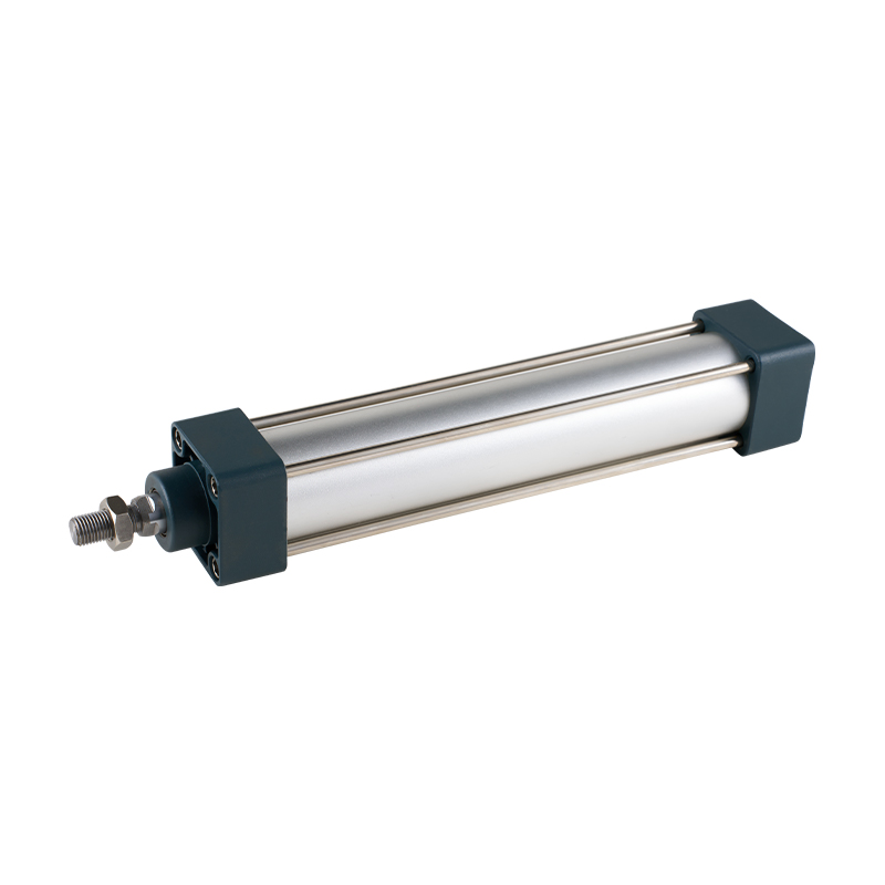 SC Series Tie Rod Standard Cylinder with Compact LengthThis tie-rod cylinder meets ISO 15552 but offers a shorter body for the same bore. Its special sealing and high-temperature option make it a practical choice for reliable automation in limited spaces.View Product →
Round-body miniature cylinders use no tie rods at all. The caps screw directly onto a drawn stainless or aluminum tube, giving a slim, light, hygienic body. They are common in small fixtures, clamps, and medical devices where the reduced external bulk matters more than rebuild serviceability. The international dimensional frame ISO 6432 governs these small units up to about 25 mm bore.
Compact cylinders squeeze the same force into a much shorter overall length. They use an extruded aluminum profile with an integral sensor groove, and the piston rod is often supported by guide rods for greater anti-rotation stability. ISO 21287 defines their mounting interface. They are widely used in clamping, stopping gates, tool changers, and any spot where a standard cylinder simply does not fit.
When comparing structural variants, remember that the barrel, seals, and rod still do the heavy lifting. A compact cylinder will always have a shorter stroke limit than a tie-rod unit of the same bore because the long guide envelope is reduced.
Rodless Cylinders: Same Functions Without the Rod
Rodless cylinders keep the barrel, piston, seals, and cushioning concept, but remove the external piston rod entirely. The piston drives a carriage that travels along the outside of the barrel. This layout saves roughly 50 percent of the installation length compared to a conventional rod-type cylinder for the same stroke, eliminates rod buckling issues on long strokes, and allows strokes up to several meters.
Two physical principles exist. Magnetically coupled rodless cylinders transmit force from the internal piston to the external carriage through strong permanent magnets; the barrel is fully sealed, which makes them clean and leak-free, but the coupling can disengage under shock loads or vertical mounting with heavy payloads. Mechanically coupled rodless cylinders use a longitudinal slot in the barrel, closed by a stainless steel sealing band, with a mechanical bridge connecting piston and carriage. They transmit higher forces and handle shock better, but the sealing band and wiper over the slot are additional wear points that need inspection.
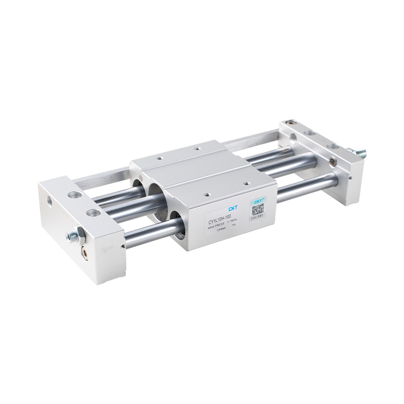 CY1L Series Magnetic Coupled Rodless Cylinder with Ball BearingsThis rodless cylinder uses magnetic coupling for leak-free, space-saving linear motion. The ball bearing carriage handles lateral loads smoothly, making it ideal for compact long-stroke transfer applications.View Product →
The engineering tradeoff is simple: use magnetically coupled rodless cylinders for clean medium-speed transfer applications, and use mechanically coupled units when the load is heavy or the motion includes impact. In both cases, pay attention to the carriage guidance, because the absence of a rod means all lateral and moment loads must be handled by the carriage bearings.
Failure Modes, Symptoms, and Root Causes
Knowing the parts is only half the battle; the other half is recognizing which part fails first when performance drops. The table below links common symptoms to the most likely component and the repair direction.
| Observed Symptom | Component Involved | First Check and Action |
|---|---|---|
| Sluggish or squeaking movement | Rod seal, wiper, piston guide ring | Check lubrication and air filter; disassemble and inspect seal lips |
| Air bubbles around the rod | Rod seal | Run a finger over the rod to feel for scratches; replace seal and consider rod resurfacing |
| Cylinder creeps when air is switched off | Piston seal | Internal leakage across the piston; replace piston seal and check barrel wear |
| Loud metallic clang at stroke end | Cushioning system | Adjust cushion needle; inspect cushion seal and replace if worn |
| Sensor does not detect the piston | Magnetic piston band or switch | Confirm the cylinder is a magnetic type; reposition the switch on the barrel groove |
| Cylinder will not move under pressure | Piston, barrel, mounting | Verify the load is not jammed; disassemble to check swollen seals or scored barrel |
Before replacing any cylinder, always confirm the basics: supply pressure at the inlet, filter-regulator condition, and whether the solenoid valve actually shifts. A dry, dirty air supply wears out seals three to five times faster than filtered and lightly lubricated air, no matter how good the cylinder parts are.
Using Component Knowledge When Buying a Pneumatic Cylinder
A buyer who understands the parts of a pneumatic cylinder stops comparing only price and bore size. The practical way to specify a cylinder is to build the complete component checklist before opening the catalog:
- Bore size and required thrust at the actual operating pressure
- Stroke length and the rod diameter needed to resist buckling
- Mounting style and rod-end accessory type
- Cushioning type: adjustable, self-adjusting, or none
- Magnetic piston and sensor type, plus sensor cable length
- Port thread size and supply air quality at the installation point
- Ambient temperature range, humidity, and dust level
Then evaluate the manufacturing evidence. Surface treatment details, seal material, and machining tolerances are not trade secrets; a reputable supplier publishes them or states them on request. A manufacturer that performs its own machining and finishing, such as Zhejiang CKT Pneumatic with its two decades of pneumatic component production, is usually in a better position to hold tight barrel and rod tolerances than an assembly-only seller. See the company profile for the production history and manufacturing principles.
For space-constrained machine designs, a compact cylinder with a short overall length and a built-in sensor groove is often the right choice. The CQ2-series thin cylinders keep the same bore force output while reducing the installation footprint, which makes them practical for clamping sections and tool changers.
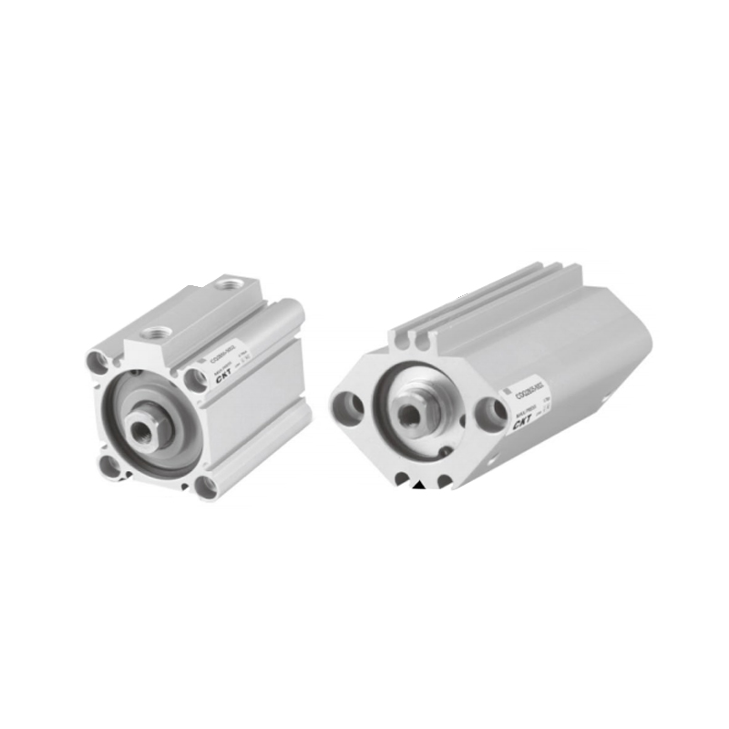 CQ2 Series Thin Cylinder with Flush Magnetic SwitchDesigned for tight spaces, this thin cylinder provides consistent force while minimizing footprint. Its recessed magnetic switch prevents snagging and works in wet or strong-magnetic-field conditions.View Product →
Finally, set realistic life expectations. A well-built standard cylinder running on clean, filtered, lightly lubricated air at moderate speed will often serve five million cycles or more. In a hot, humid, unfiltered environment, even an expensive cylinder can fail before one million cycles. The cheapest way to extend cylinder life is not a cheaper cylinder; it is better air preparation and a proper alignment between the rod and the guided load.
Frequently Asked Questions
What are the main parts of a pneumatic cylinder?
The main parts are the barrel, front and rear end caps, piston, piston rod, seals, guide rings and rod bearing, cushioning system, and air ports. A magnetic piston band and external sensors are additional components used when position feedback is required.
Which part of a pneumatic cylinder wears out first?
In most field failures, the rod seal and wiper fail first, especially when the air supply is dirty or the installation creates side loads. The piston seal is the second most common wear item, failing when the barrel bore becomes scored or when incompatible lubricants cause the rubber to swell.
Do all pneumatic cylinders need a magnetic piston?
No. A magnet is only needed when an external sensor must detect the piston position. If you order a non-magnetic cylinder and later decide to add position feedback, the switch will not respond because there is no magnetic field to trigger it.
What is the difference between single-acting and double-acting cylinder parts?
A single-acting cylinder has one working port and a spring that returns the piston to its home position; the spring adds a counterforce that reduces net output and grows over fatigue. A double-acting cylinder has two ports in the end caps, with compressed air alternately driving extension and retraction, giving higher and more balanced force in both directions.
Why is my cylinder moving slowly and jerkily?
The usual reasons are stick-slip from dry seals, a scored barrel or rod caused by contaminated air, or a speed control valve that is throttled too far. Check the air preparation units first, then inspect the rod surface and the seal condition before suspecting the machine load.
Can a worn pneumatic cylinder be repaired?
Yes, if the barrel and rod are still within tolerance. Replacing the seals, guide rings, and wiper with a proper seal kit restores most cylinders. If the barrel bore is deeply scored or the rod is bent, however, replacing the entire cylinder is usually more economic than grinding and re-plating the rod.
Every part of a pneumatic cylinder exists for a reason: the barrel defines the precision envelope, the piston converts pressure into force, the rod delivers it to the load, and the seals, guide rings, cushioning, and sensors protect and supervise that motion. The final conclusion is the same one a maintenance engineer reaches after a hundred cylinder rebuilds: focus on barrel treatment, rod finish, and seal system, and the rest of the cylinder will behave itself.
Use the component maps and failure tables above when you evaluate a quote, troubleshoot a slow axis, or compare a cheap alternative against the original specification. For a deeper explanation of how internal forces and motion evolve at speed, the engineering column on what happens behind the power muscles of pneumatic air cylinders is a practical follow-up reading.
As a final purchasing rule: never let a cylinder be chosen purely by bore and stroke. Ask the supplier about the anodizing, the rod plating, the seal compound, and the cushioning capacity. A cylinder is a small assembly of precisely coordinated parts, and the buyer who understands those parts will almost never regret the decision.