

 中文简体
 English


Content
- 1 How a Rodless Pneumatic Cylinder Transmits Linear Motion Without a Rod
- 2 Magnetic Coupled vs Mechanical Coupled: Key Differences
- 3 Why Rodless Cylinders Reduce Machine Footprint and Eliminate Rod Buckling
- 4 Selection Checklist: Seven Checks Before You Confirm a Rodless Cylinder
- 5 Sizing and Force Calculation with a Worked Example
- 6 Speed, Cushioning, and Stopping Precision
- 7 Reliability, Service Life, and the Failure Modes That Appear in Real Plants
- 8 Maintenance and Practical Best Practices
- 9 Cost and Total Cost of Ownership
- 10 Frequently Asked Questions
- 10.1 What is the main difference between a rodless cylinder and a standard cylinder?
- 10.2 How much space does a rodless cylinder save?
- 10.3 Can a magnetic-coupled rodless cylinder slip, and what happens if it does?
- 10.4 What is the maximum stroke length of a rodless cylinder?
- 10.5 Do I need an external guide rail with a rodless cylinder?
- 10.6 What operating speed can a rodless cylinder achieve?
A rodless pneumatic cylinder delivers the same pushing and pulling force as a conventional rodded cylinder but fits in roughly half the space along the axis of travel. For a 600 mm stroke in a 32 mm bore size, a standard tie-rod cylinder needs about 1,300 mm of machine length when the rod is fully extended; a magnetic-coupled rodless cylinder of the same stroke occupies roughly 780 mm installed length. The envelope saving is the main reason automation engineers use rodless cylinders for gantry axes, welding fixtures, packaging pushers, and door-opening mechanisms.
Before selecting a series, you need the working principle, the real force capacity under load, the reliability limits of magnetic coupling versus mechanical coupling, and the maintenance conditions that keep the unit alive for thousands of operating hours. The guidance below covers all of that with representative dimension data, sizing examples, and a comparison of the two major rodless architectures. If you want to start from the catalogue, the complete rodless cylinder product range groups the magnetic and mechanical series side by side. The selection logic below works for every series, regardless of the brand.
How a Rodless Pneumatic Cylinder Transmits Linear Motion Without a Rod
A rodless pneumatic cylinder is a single structural unit: the barrel, the piston, and a moving carriage. The piston travels inside the barrel under differential pressure. The load attaches to the carriage, which travels outside the barrel. Because the carriage is always directly above the piston, the total unit length never grows beyond the stroke plus the two end caps. The barrel of a magnetic-coupled unit is closed; the barrel of a mechanical-coupled unit has a long slot and a fork that transfers the piston force to the carriage.
Magnetic-Coupled Design
The piston and the carriage each carry rows of permanent neodymium magnets arranged with opposite poles facing each other across the barrel wall. When the piston moves, the magnetic field pulls the carriage with it. Because the barrel is closed, no sealing band is needed, there is no static leak path, and the cylinder handles moderate axial and lateral loads without additional guides. The practical limit is the strength of the magnetic link: if the axial force or acceleration exceeds the magnetic holding force, the carriage stops following the piston and the cylinder slips. The slip is not destructive in itself, but it disrupts motion and can damage a tool if it happens under a heavy vertical load.
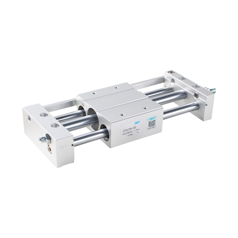 CY1L Series Magnetic Coupled Rodless Cylinder with Ball Bearing GuideThis cylinder transmits motion through magnetic coupling, eliminating piston rod leakage and saving space. Its ball bearing guide supports smoother travel and better load adaptation, making it a strong option where compactness and sealing matter.View Product →
Mechanical-Coupled Design
Mechanical coupling uses a longitudinal slot machined into the barrel or extrusion profile. A hardened steel yoke connects the piston head to the carriage through the slot. Two stainless steel bands cover the slot: an inner pressure seal that contains the compressed air and an outer dust band that keeps debris out. As the carriage passes, the yoke peels the bands open and re-seats them behind it. This construction transmits the full piston force without a magnetic limit and can run faster, but the bands and the wipers are wear items, and the slot area always requires clean, dry compressed air.
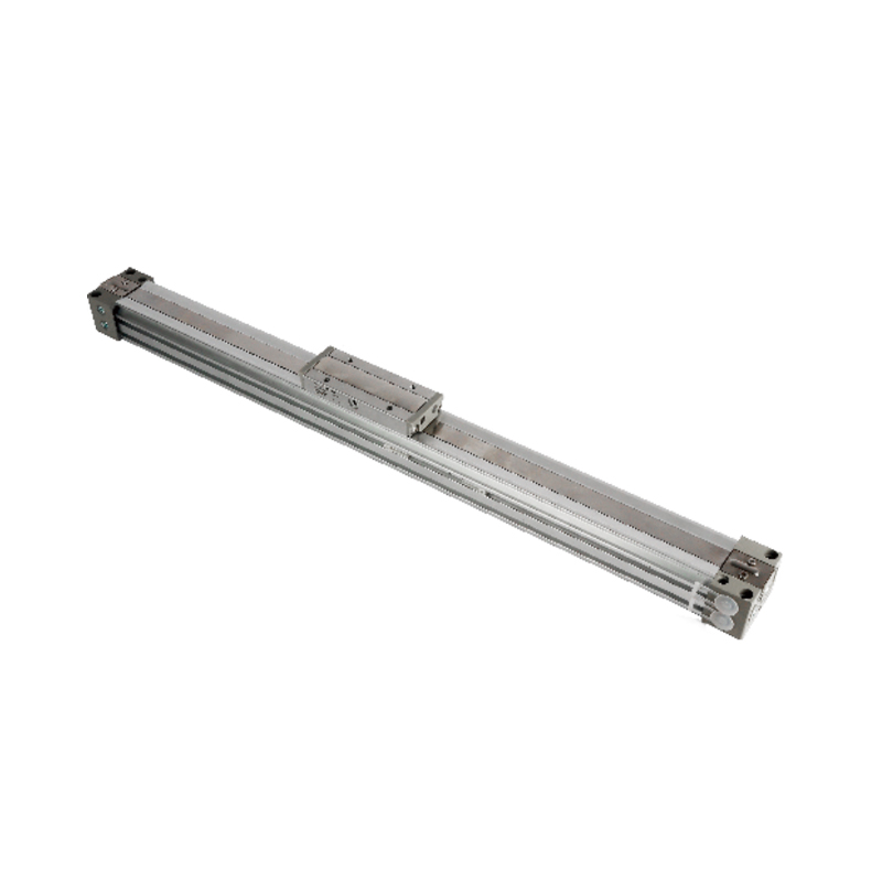 MY1B Series Mechanically Coupled Rodless Cylinder with Flexible Rail OptionsThis basic mechanical joint cylinder offers bore sizes from 10 to 100 mm and works with third-party rail guides. It delivers full piston force without magnetic slip, suited for automation layouts where space is tight and load demands are high.View Product →
Magnetic Coupled vs Mechanical Coupled: Key Differences
The table below compares the two architectures on the factors that actually change the machine design. Read it before choosing a family, because the coupling type determines your load limit, speed limit, and maintenance schedule.
| Parameter | Magnetic Coupled (CY1L / CY1S type) | Mechanical Coupled (MY1B / MY1H type) |
|---|---|---|
| Coupling element | Rows of permanent neodymium magnets | Steel yoke entering the barrel slot |
| Barrel structure | Closed bore, no slot, no external band | Slotted bore with inner pressure band and outer dust band |
| Maximum typical speed | About 1 m/s under normal filtered supply | Up to 3 m/s with cushions and a guide type |
| Axial load limit | Set by magnet holding force; use a 2:1 safety margin | Follows the normal piston force calculation; no coupling limit |
| Overturning moment capacity | Low; an external linear rail is usually required | High with the linear-guide series (MY1H / MY2H) |
| Contamination sensitivity | Low; the barrel is fully closed | Band wipers need regular cleaning in dusty shops |
| Maintenance wear points | Piston seal and carriage bearing strips | Same two, plus the inner and outer sealing bands |
| Typical stroke range | 100 to 3,000 mm in the CY1L / CY1S series | 150 to 3,000 mm in MY1B; longer versions in MY3A / MY3B |
For a pick-and-place gantry where the tool runs on an external linear rail, either architecture works. For a vertical lifting axis that carries a brake or a safety valve, the mechanical-coupled type removes the magnetic slip risk. For clean and high-speed sorting equipment, a mechanical-coupled guide type produces the stiffest response. The next section explains the dimension advantage in measurable terms.
Why Rodless Cylinders Reduce Machine Footprint and Eliminate Rod Buckling
The envelope difference is not linear. A rodded cylinder always extends: the barrel contains the piston, and the rod slides out. The fully extended length is roughly two times the stroke plus the end closures. A rodless cylinder is fixed: the total length equals the stroke plus two end caps, which is why it fits inside a frame or a guard without extra clearance for a protruding rod.
| Stroke | Rodded Cylinder Installed Length (Fully Extended) | Rodless Cylinder Installed Length | Space Saved |
|---|---|---|---|
| 300 mm | 760 mm | 460 mm | 39 percent |
| 600 mm | 1,320 mm | 780 mm | 41 percent |
| 1,000 mm | 2,120 mm | 1,180 mm | 44 percent |
| 2,000 mm | 4,120 mm | 2,240 mm | 46 percent |
The other mechanical argument is column buckling. A long piston rod acts like a column under compression; a 32 mm bore cylinder with a 1,000 mm stroke and a 12 mm rod deflects sideways if the load exceeds the Euler buckling limit. Designers historically solved this with oversized rods, rod clevises, and extra supports. The rodless cylinder removes the rod entirely, so buckling disappears as a constraint, and strokes up to 3,000 or 5,000 mm become practical in a single axis without a complex support frame.
Selection Checklist: Seven Checks Before You Confirm a Rodless Cylinder
Use this checklist before you send the order. The first four points decide whether the cylinder will move the load; the last three decide how long it will last in production.
- Force reserve. Calculate the theoretical piston force at the actual supply pressure, then use no more than 50 percent of it for the driving load. The rest covers friction, acceleration peaks, and pressure drop in the hoses.
- Coupling safety margin. For magnetic-coupled types, compare the worst-case axial load, including acceleration and any vertical component, with the catalogue holding force. A 2:1 margin is the customary minimum; below that, choose mechanical coupling.
- Moments and side loads. If the tool hangs 150 mm in front of the carriage, the moment load equals 150 mm multiplied by the tool weight, and this value must stay below the catalogue pitch-moment curve. When the moment is significant, pick a mechanical-coupled guide type.
- Stroke reserve. Add 5 to 10 percent stroke beyond the theoretical travel to cover cushions, sensor switching points, and mechanical stop positions.
- Speed and stopping energy. When 5 kg moving at 1 m/s hits the end cap, it releases 2.5 J of kinetic energy; at 2 m/s the same mass needs four times that energy. Match the cushioning system to this value.
- Sensor compatibility. Confirm that the cylinder has contactless sensor grooves compatible with your PLC input type, PNP or NPN, and that the magnetic switch can be placed near both end positions.
- Air quality and lubrication. Feed the cylinder from a filtered and dried line with at least a 5 micrometre filter. If the manufacturer allows oil lubrication, use ISO VG32 mineral oil and keep lubrication continuous; intermittent lubrication causes seal swelling and inconsistent speed.
When the application includes a bulky gripper or a two-axis head, the mechanically coupled linear-guide series such as MY1H absorbs pitch and yaw moments with no external rail. That series is the right answer when the tool overhang changes during a cycle, because the integrated guide keeps the carriage parallel to the barrel under varying load.
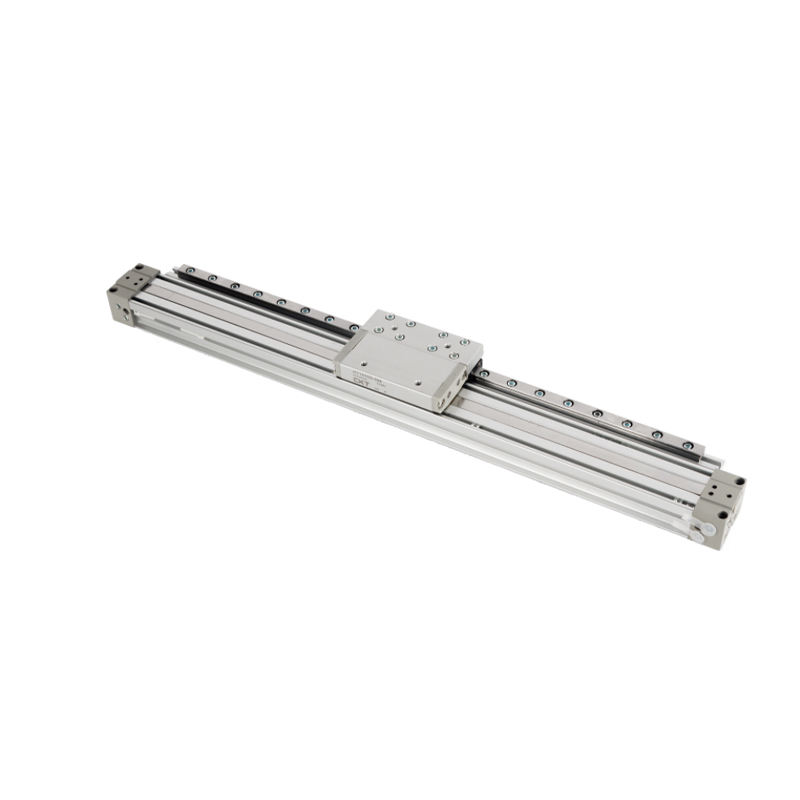 MY1H Series Mechanical Joint Rodless Cylinder with Integrated Linear GuideDesigned for pick-and-place tasks, this cylinder combines mechanical coupling with a built-in linear guide for higher rigidity and repeatability. It handles moderate loads and moments without external rails, ideal for compact precision positioning.View Product →
Sizing and Force Calculation with a Worked Example
The calculation starts from the same equation used for any pneumatic cylinder: F theoretical in newtons equals the supply pressure in MPa multiplied by the piston area in square millimetres, with the area calculated as 3.1416 x (bore / 2)2. The working pressure at the cylinder is usually lower than the regulator value because of hose resistance and flow capacity of the valve.
Worked example: a 40 mm bore rodless cylinder at 0.6 MPa has a piston area of 3.1416 x 20 x 20 = 1,257 mm2. The theoretical force is 0.6 x 1,257 = 754 N. Using the 50 percent rule, usable horizontal force is 377 N. The carriage weighs 4 kg, the fixture 6 kg, and the workpiece 3 kg, for a total of 13 kg or 127 N. The remaining 250 N allows a start acceleration of roughly 3 m/s2 after subtracting 50 N of seal friction. The drive is safely sized.
| Bore | Piston Area (mm2) | Force at 0.4 MPa | Force at 0.6 MPa | Usable Horizontal Load at 0.6 MPa |
|---|---|---|---|---|
| 25 mm | 491 | 196 N | 295 N | 147 N |
| 32 mm | 804 | 322 N | 483 N | 241 N |
| 40 mm | 1,257 | 503 N | 754 N | 377 N |
| 50 mm | 1,964 | 785 N | 1,178 N | 589 N |
| 63 mm | 3,117 | 1,247 N | 1,870 N | 935 N |
For vertical lifting, subtract the dead weight of the moving assembly from the usable force, then re-check the magnetic coupling holding force, because the full mass participates in both acceleration and deceleration. A vertical axis on a magnetic-coupled cylinder should include a fall-arrest valve or a mechanical lock if the tooling is valuable.
Speed, Cushioning, and Stopping Precision
Standard rodless cylinders run comfortably at 0.1 to 0.8 m/s. Magnetic-coupled types accept short periods up to 1 m/s; mechanical-coupled guide types reach 3 m/s in lightweight sorting applications. Above 0.5 m/s, the stroke-end cushioning becomes the component that decides the service life of the whole unit.
- Adjustable air cushions are integrated into both end caps. They work well for moderate masses and speeds up to about 1 m/s, and they can be tuned with a needle valve at commissioning.
- External hydraulic shock absorbers are the right choice when kinetic energy exceeds what the air cushion absorbs. They add length to the axis but provide repeatable stopping positions and protect the barrel over millions of cycles.
The crucial number is kinetic energy, E = 0.5 x m x v2. A 20 kg carriage moving at 0.8 m/s carries 6.4 J. A 50 kg carriage at 1.2 m/s carries 36 J. Air cushions of small bores absorb only a few joules; above 10 J, plan for an external shock absorber or reduce the speed with a flow control valve.
Under a steady side load, the magnetic coupling behaves like a stiff spring, so the carriage can sit slightly ahead of the piston when the load is high; this lost motion is typically in the range of 0.2 to 1 mm. For positioning at discrete stops, fit a mechanical stop and a magnetic switch on the barrel; do not rely on the cylinder alone for sub-millimetre repeatability.
Reliability, Service Life, and the Failure Modes That Appear in Real Plants
Reliability of a rodless cylinder is defined by three components: the piston seal, the carriage bearing strips, and, for mechanical types, the slot bands. A closed-bore magnetic type has no band wear; its piston seal operates in a smooth extruded aluminium barrel, which is the same technology used in a standard cylinder. With clean, dry air, magnetic-coupled rodless cylinders in pick-and-place service run through millions of cycles before a seal change is needed. The decisive factor is not the coupling; it is the condition of the compressed air.
The longevity of the unit also depends on the straightness of the barrel and the dimensional accuracy of the slot. CKT, a manufacturer producing pneumatic components since 2002, machines its rodless cylinder barrels and guide rails in-house, which keeps the piston seal aligned with the carriage over the full stroke. A supplier with in-house production can answer tolerance questions during a machine debug phase, which matters more than the drawing alone.
| Failure Mode | Most Common Cause | Cost-Effective Fix |
|---|---|---|
| Carriage sticking | Moment overload bends the bearing strips | Add an external guide rail, reduce tool overhang |
| Magnetic slip | Axial load above the coupling holding force | Choose a larger bore or a mechanical-coupled type |
| Pressure loss at the slot | Inner sealing band scored by contamination | Clean the band wipers, add an air dryer |
| Slow or jerky movement | Water condensate or interrupted lubrication | Service the FRL unit, switch to continuous lubrication |
| Loud stroke-end impact | Cushion needle closed or impact energy too high | Open the cushion valve or mount a shock absorber |
Maintenance and Practical Best Practices
A rodless cylinder is not maintenance-free, but the routine is short and predictable. The three routines below cover most production environments.
- Every shift: check the FRL unit, drain the filter bowl when the water level approaches the mark, and confirm the supply pressure on the gauge.
- Every week: wipe the barrel and the exposed guide surfaces, inspect sensor cables for chafing, and listen for stroke-end impacts that indicate a drifting cushion setting.
- Every month: on mechanical-coupled types, remove the dust band wipers, clean them, and inspect the stainless steel band for scoring; verify cushioning screws have not moved.
- Every six months: measure the travel speed and stroke-end impact and compare them with the commissioning record; replace seals if the speed drops below 80 percent of the original value.
A cylinder running at 0.5 m/s for 16 hours a day covers more than 28 km of piston travel per day. That is why regular air-quality maintenance matters more than the initial quality of the cylinder: a few grams of water entering the barrel over a weekend can undo months of trouble-free operation.
Cost and Total Cost of Ownership
The purchase price of a rodless cylinder is usually higher than that of a rodded cylinder of the same bore and stroke, but the installed cost often favours the rodless design because the machine frame is shorter, the alignment work is simpler, and the rod-support hardware disappears. The table below lists the cost items in a typical machine build.
| Cost Item | Rodless Cylinder | Rodded Cylinder |
|---|---|---|
| Base price | Higher, typically 1.3 to 2 times | Lower |
| Frame and mounting | Shorter and lighter machine frame | Longer frame plus rod support brackets |
| Installation time | One unit, minimal alignment | More parts, rod eyes and supports need alignment |
| Spare parts | One complete unit plus seal kit | Cylinder, rod attachments, supports, seals |
| Energy per cycle | Lower moving mass reduces acceleration energy | Higher moving mass on long strokes |
For a machine that cycles 12 times per minute, the cost per cycle matters. A rodless carriage carries only the tool weight; a long rodded cylinder accelerates a heavy rod on every stroke. Over 20,000 operating hours, the difference in moving mass can offset a large share of the initial price gap.
Frequently Asked Questions
What is the main difference between a rodless cylinder and a standard cylinder?
A rodless cylinder has no protruding piston rod. The piston moves inside the barrel while the carriage moves outside, and the two are coupled magnetically or mechanically. The total installed length is approximately the stroke plus two end caps, whereas a rodded cylinder extends by the full stroke during operation.
How much space does a rodless cylinder save?
For strokes from 300 to 2,000 mm, the installed envelope saving is typically 39 to 46 percent compared with a rodded cylinder of the same bore and stroke, as shown in Table 2 above. The saving grows with stroke because the rodless design does not double the occupied length.
Can a magnetic-coupled rodless cylinder slip, and what happens if it does?
Yes, slipping occurs when the axial load or acceleration exceeds the magnetic holding force. The carriage stops following the piston, and the cylinder fails to move the load. There is no permanent damage, but a vertical axis can drop the tooling if no safety valve is installed. Keep the worst-case load below 50 percent of the catalogue holding force.
What is the maximum stroke length of a rodless cylinder?
Standard magnetic and mechanical series commonly cover strokes up to 3,000 mm, and some heavy guide series go beyond 5,000 mm. A rodded cylinder beyond 2,000 mm requires rod supports and larger rod diameters to avoid sagging and buckling, which adds cost and complexity.
Do I need an external guide rail with a rodless cylinder?
Only when the moment loads exceed the catalogue ratings. Magnetic-coupled types are suited to moderate side loads; mechanical-coupled guide series such as MY1H and MY2H integrate a linear guide and can absorb larger pitch, yaw, and rolling moments. For a heavy gripper hanging far from the carriage, an external rail is the safer option.
What operating speed can a rodless cylinder achieve?
Magnetic-coupled types are usually limited to about 1 m/s, while mechanical-coupled guide types reach up to 3 m/s in light-load sorting applications. For reliable, maintenance-friendly operation, design for 0.3 to 0.8 m/s and use flow-control valves to stabilise the speed.
A rodless pneumatic cylinder is the right answer when the stroke is long relative to the machine envelope, when a piston rod would buckle, or when the carriage must carry a guided load without extra supports. The two architectures cover almost every industrial case: magnetic coupling for clean, medium-duty axes; mechanical coupling with a guide series for heavy loads, high speeds, and severe moments.
Size the force at 50 percent usable load, respect the coupling margin, feed the unit from a filtered and dried air supply, and the rodless cylinder will outlast most of the machine around it.