

 中文简体
中文简体
 English


Content
- 1 The Seven Functional Groups in a Pneumatic System
- 2 Directional Control Valves: The Switching Brain of the Circuit
- 3 Air Cylinders: Sizing Force, Stroke, and Mounting Correctly
- 4 F.R.L. Units: Protecting the Entire Circuit
- 5 Vacuum Components: Lifting and Holding Without Mechanical Clamping
- 6 Fittings, Tubing, Silencers, and Buffers: The Supporting Cast
- 7 What to Check When Sourcing Pneumatics Components From a Manufacturer
- 8 Frequently Asked Questions About Pneumatics Components
- 8.1 What is the difference between a 5/2 and a 5/3 solenoid valve?
- 8.2 How do I calculate the cylinder force I actually need?
- 8.3 What size F.R.L. unit do I need for a small automation machine?
- 8.4 Can one vacuum generator run multiple suction cups?
- 8.5 How often should the F.R.L. filter be drained?
- 8.6 When are stainless steel one-touch fittings necessary?
Pneumatics components are the individual building blocks that produce, condition, distribute, and consume compressed air in automated machinery. A complete actuation cycle, whether clamping, lifting, rotating, gripping, pushing, or ejecting, is the result of several groups of components working together: air preparation units, directional control valves, actuators, vacuum elements, flow control and check valves, sensors and switches, and connection hardware such as fittings, tubing, and silencers.
The direct answer for any machine builder or maintenance engineer is simple: you cannot select a single pneumatics component in isolation. Every reliable circuit starts with the actuator, works backward to the directional valve, then to the F.R.L. unit, and finally to tubing and fittings that must carry the required flow without excessive pressure loss. This guide gives you the selection criteria for each group, with the numbers, tolerances, and practical checks you need at the drawing board and on the shop floor.
The Seven Functional Groups in a Pneumatic System
Before choosing any part, map your circuit against the seven functional groups. Every group has a defined job, and skipping or undersizing one group will degrade the performance of the others.
| Group | Primary role | Typical components |
|---|---|---|
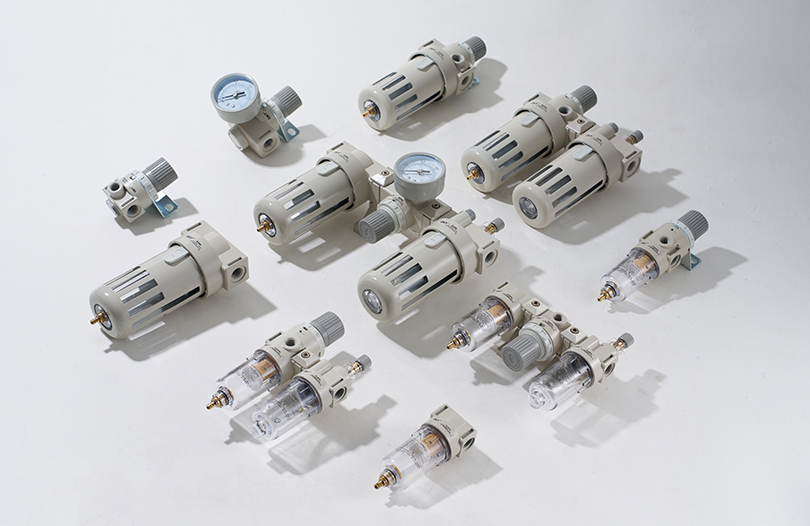
| Air preparation (F.R.L.) | Filters particles and condensate, regulates pressure, adds lubrication | Air filters, pressure regulators, lubricators, F.R.L. combos |
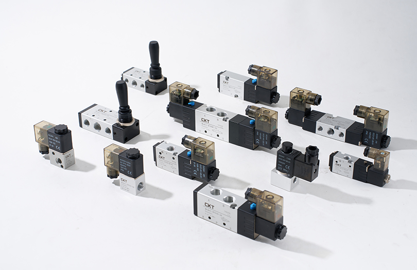
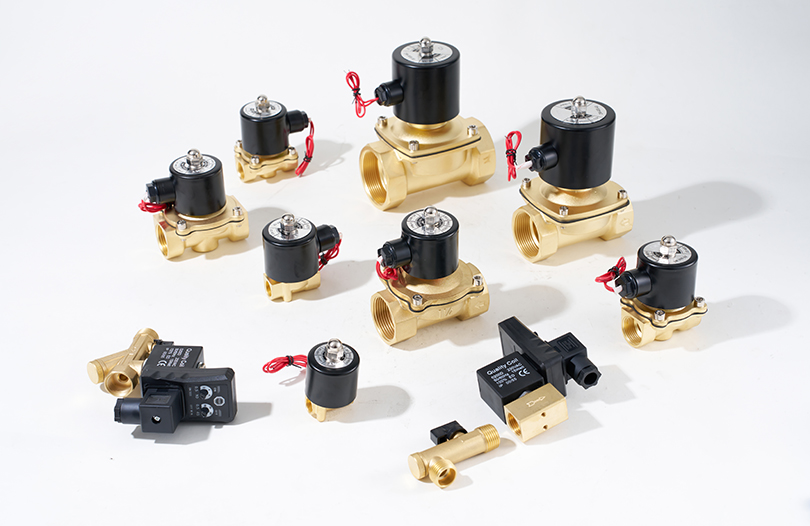
| Directional control valves | Start, stop, and switch the airflow path | 2/2, 3/2, 5/2 solenoid valves; air pilot, manual, mechanical valves |
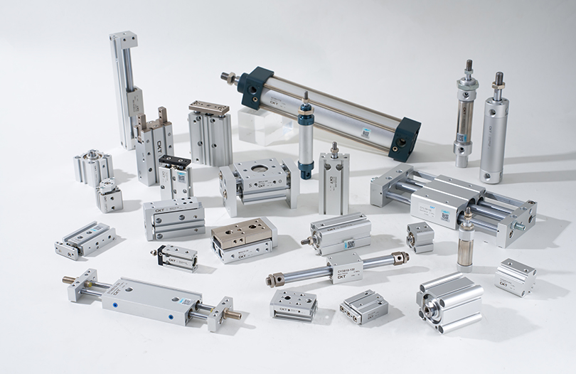
| Actuators | Convert air pressure into linear or rotary motion | Standard cylinders, thin cylinders, rodless cylinders, grippers, rotary cylinders |
| Vacuum components | Generate negative pressure and grip workpieces | Vacuum generators, suction cups, vacuum filters, vacuum regulators, vacuum pressure gauges |
| Flow control and check valves | Adjust actuator speed and prevent reverse flow | Speed control valves, check valves, quick exhaust valves, pilot-operated check valves |
| Sensors and switches | Detect piston position, pressure, and status | Magnetic switches, digital pressure switches |
| Connection and auxiliary hardware | Deliver air, reduce noise, absorb impact | One-touch fittings, PU tubes, silencers, hydraulic buffers |
When the full chain works together, a machine can repeat a motion thousands of times with only a few percent of variation. When one group is mis-sized, the failure usually shows up somewhere else: a small fitting starves a fast cylinder, a dirty filter starves a valve, and a lightly cushioned cylinder hammers its end cap.
Directional Control Valves: The Switching Brain of the Circuit
Directional control valves decide when and where compressed air flows. Most pneumatic circuits in industrial automation operate at 0.4 to 0.7 MPa (4 to 7 bar), and the valve must handle that pressure while shifting quickly and reliably.
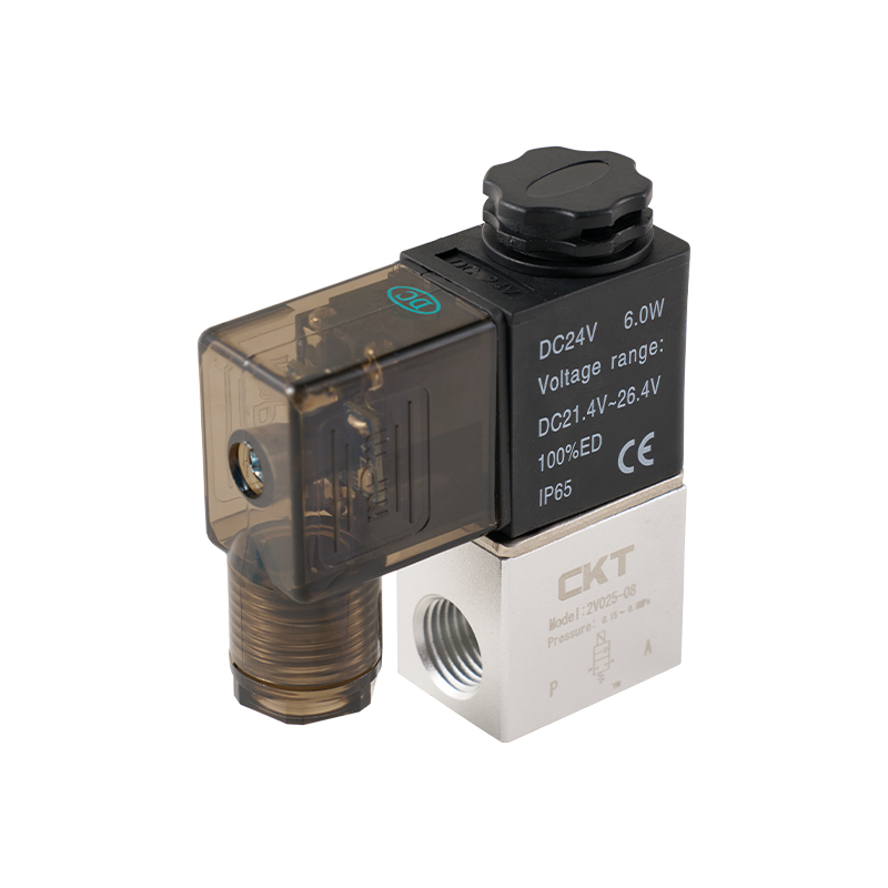
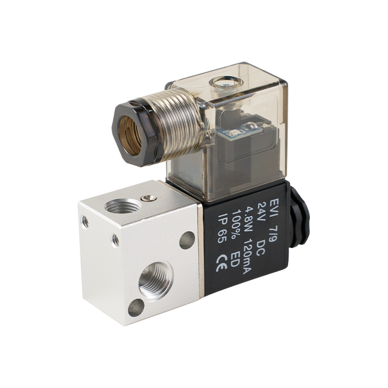
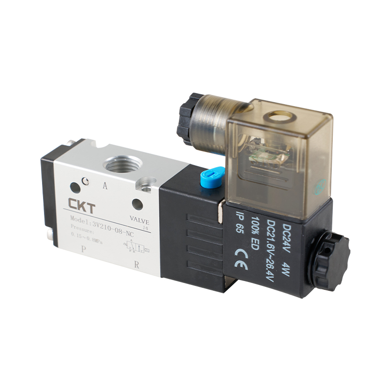
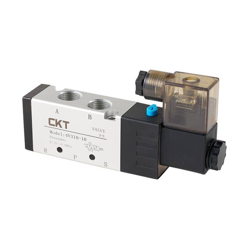
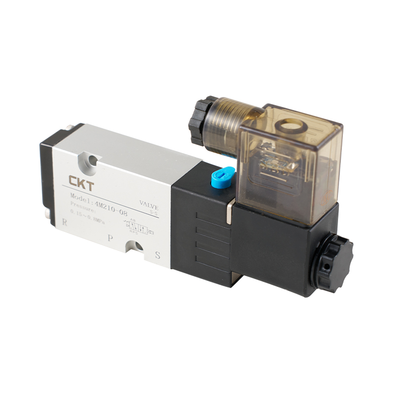
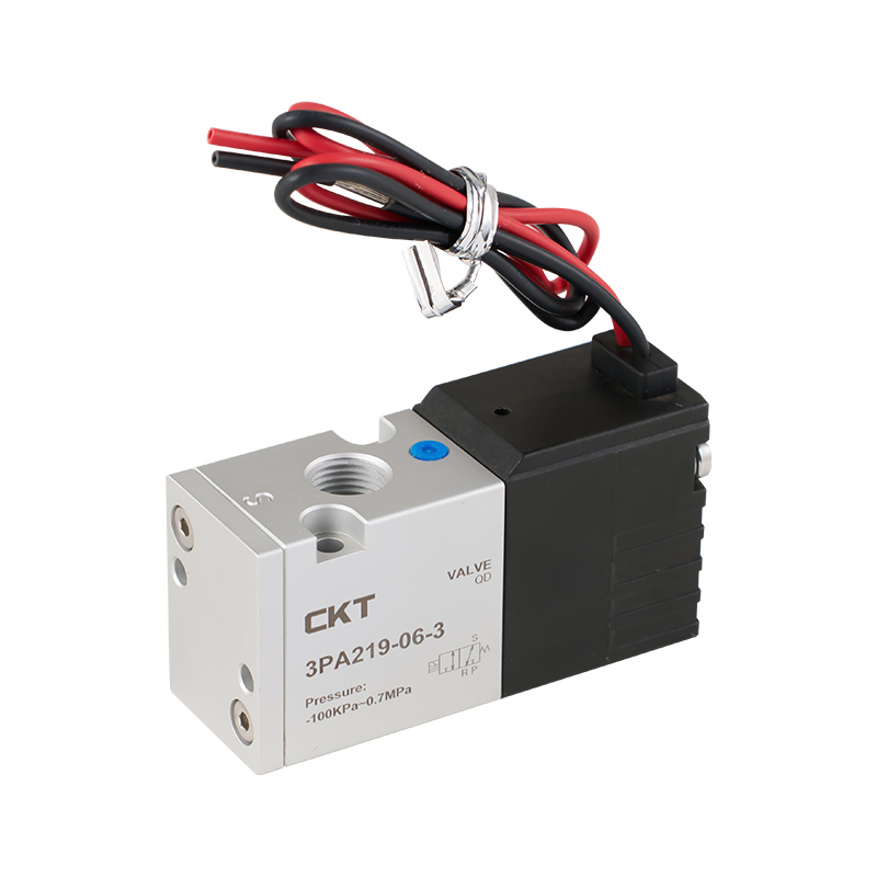
A 5/2 valve has five ports and two positions, making it the standard choice for double-acting cylinders. A 5/3 valve adds a center position, which can be closed-center for holding, exhausted-center for free movement, or pressurized-center for specific mid-stroke applications. A 3/2 valve is common for single-acting cylinders or for piloting a larger main valve.
Direct-Acting versus Pilot-Operated
Direct-acting valves switch by energizing the solenoid coil directly against the spool. They suit small flow rates, low power consumption, and fast response. Pilot-operated valves use the supply air itself to move the main spool after a small pilot solenoid opens, which handles larger flows with a smaller coil and lower electrical draw. For a typical machine cabinet, pilot-operated 5/2 valves in the 4V series class are the workhorse because they cover port sizes from G1/8 to G1/2 with nominal flow ratings from about 700 to 4500 L/min.
Work through this checklist when sizing a solenoid valve:
- Confirm the number of ways and positions against your actuator.
- Choose the actuation type: single solenoid with spring return for simple extend-and-retract, double solenoid for fail-in-place or latching behavior.
- Select the operating voltage. 24 V DC is the dominant standard for PLC-controlled machines, while 110 V AC and 220 V AC remain common in retrofit lines.
- Verify flow capacity: compare the valve nominal flow with the cylinder air consumption at the required cycle rate.
- Match the port size to your tubing diameter and check whether you need individual wiring or a manifold assembly.
| Valve class | Port size | Nominal flow at 0.6 MPa |
|---|---|---|
| 4V110 series | G1/8 | About 700 L/min |
| 4V210 series | G1/4 | About 1200 L/min |
| 4V310 series | G3/8 | About 2500 L/min |
| 4V410 series | G1/2 | About 4500 L/min |
Nominal flow is measured at a defined pressure drop, so always compare valves using the same reference condition. If your application is already defined, the 4V series pilot-operated 5-way solenoid valve family covers most single-cylinder and multi-cylinder machines found in packaging, assembly, and material handling equipment.
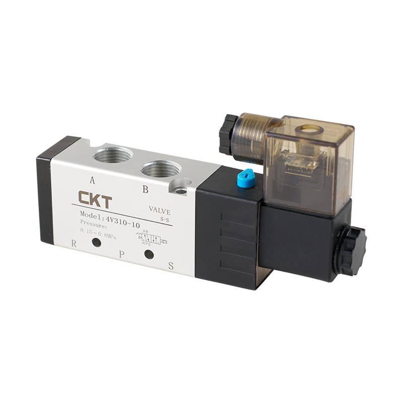 4V Series Pilot Operated 5-Way Solenoid Valve for Industrial PneumaticsThis pilot-operated 5-way solenoid valve family suits packaging, assembly, and material handling machines, offering reliable cylinder reciprocation and optional three-position central functions for load holding or safety release.View Product →
Air Cylinders: Sizing Force, Stroke, and Mounting Correctly
Air cylinders turn compressed air into linear force. The two numbers that define a cylinder are bore and stroke: bore determines force, stroke determines travel. The theoretical thrust is calculated as:
F = P x A, where F is the theoretical force in newtons, P is the working pressure in MPa, and A is the piston area in square millimeters.
Real cylinders lose some force to seal friction and internal resistance, so use a load ratio rather than the theoretical maximum. A common rule is 50 to 70% of theoretical force for horizontal motion and 30 to 50% for vertical lifting or high-speed motion. For example, at 0.6 MPa a 63 mm bore cylinder produces about 1870 N of theoretical thrust, so the practical working load should stay between 935 and 1310 N in a horizontal push application.
| Bore (mm) | Piston area (cm2) | Theoretical thrust at 0.6 MPa (N) |
|---|---|---|
| 32 | 8.04 | 482 |
| 40 | 12.57 | 754 |
| 50 | 19.63 | 1178 |
| 63 | 31.17 | 1870 |
| 80 | 50.27 | 3016 |
| 100 | 78.54 | 4712 |
The pull stroke produces less force than the push stroke because the piston rod reduces the effective area. If you are using the retract stroke for the main working force, calculate with the annular area, roughly 10 to 15% lower than the full bore area depending on rod diameter.
Beyond bore size, check four selection details:
- Mounting style: foot, flange, trunnion, clevis, or self-aligning. The mounting must absorb reaction force along the cylinder axis.
- Cushioning: adjustable air cushions at both ends protect the cylinder from impact at speeds above 0.3 m/s.
- Magnetic piston: a built-in magnet allows a magnetic switch to detect the piston position for PLC feedback.
- Rod size and buckling: long strokes with high side loads may require a larger rod or a guided version.
If your machine needs interchangeable standard actuators, tie-rod type cylinders such as the SC series are the most common choice because they offer robust construction, easy service, and broad bore and stroke coverage for both new builds and replacement work.
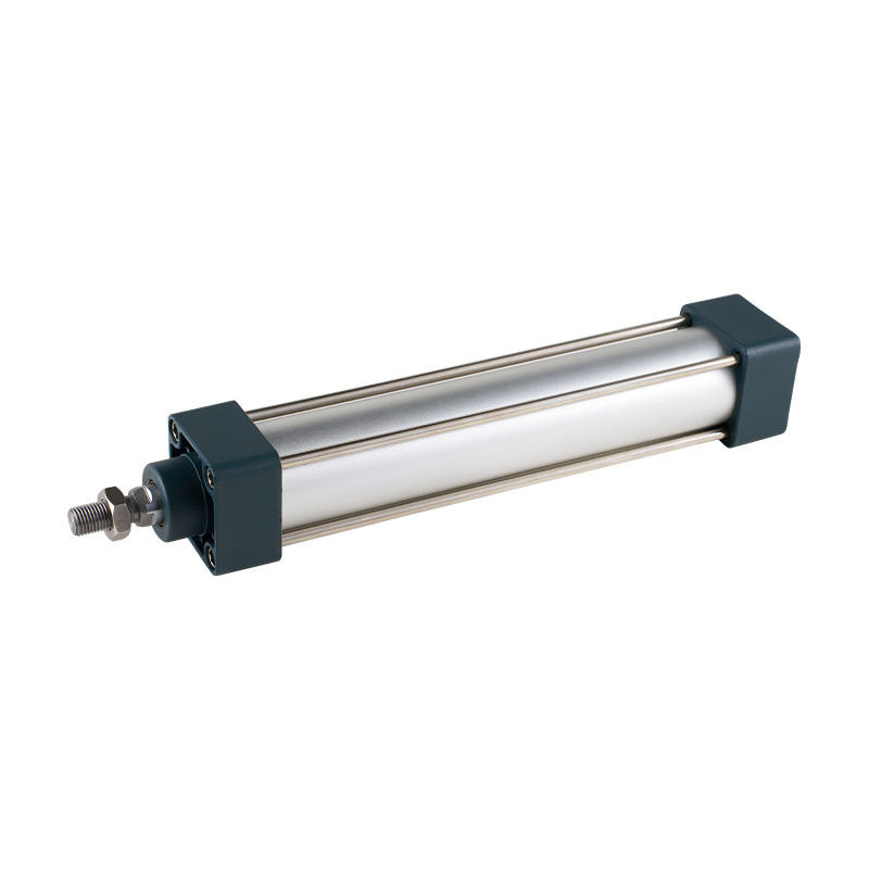 SC Series Tie-Rod Type Standard Pneumatic CylinderA robust tie-rod cylinder with broad bore and stroke options, providing dependable linear actuation for interchangeable standard actuators and replacement builds, with adjustable cushioning and high-temperature sealing.View Product →
F.R.L. Units: Protecting the Entire Circuit
F.R.L. stands for filter, regulator, and lubricator. The filter removes solid particles and condensed water from the compressed air, the regulator holds downstream pressure stable regardless of supply fluctuations, and the lubricator adds a fine oil mist to extend seal life in valves and cylinders. For many clean and dry applications, a two-piece filter-regulator unit is enough, while a three-piece F.R.L. is standard for general factory air.
A common filtration element grade is 5 microns, which catches most pipe scale, rust, and compressor wear particles before they reach the valve spool. If the machine uses sensitive components such as precision regulators or vacuum ejectors, add a secondary filter with a finer grade. The regulator pressure range is typically 0.05 to 0.85 MPa, which covers the working pressure of almost every standard cylinder and valve.
Sizing an F.R.L. unit is about flow, not port size alone. Add up the air consumption of all cylinders and valves that run simultaneously, then select an F.R.L. whose rated flow is 1.5 to 2 times that peak demand. For a single machine cabinet with several small cylinders, a G1/4 unit handling roughly 1500 to 2500 L/min is usually sufficient; a large multi-station machine with big-bore cylinders needs a G3/8 or G1/2 unit to avoid a pressure drop that slows every actuator on the line.
Installation and Maintenance Rules
- Mount the F.R.L. close to the air inlet and before any valves or cylinders.
- Install the filter bowl vertically so condensate collects at the bottom.
- Drain the filter bowl daily in humid conditions, or fit an automatic drain.
- Check the regulator pressure gauge against actual actuator force requirements.
- Fill the lubricator with the correct grade of turbine oil and adjust the drip rate so the circuit receives a small, consistent amount of oil.
Pressure matching between the F.R.L. unit, the valve, and the cylinder matters more than many maintenance teams realize. An oversized regulator with a small-bore cylinder can cause instability, while an undersized filter creates a starvation condition that looks like a valve or cylinder fault. The technical details behind these failures are examined in our article on pressure matching and installation sealing for pneumatic components.
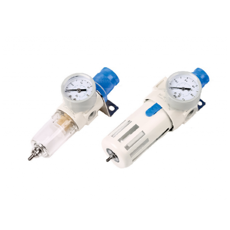 AFR/BFR Series Pressure Regulating Filter with Self-Locking MechanismA lightweight filter-regulator unit that stabilizes downstream pressure while filtering particles, featuring a press-in self-locking mechanism to preserve set pressure, ideal for maintaining proper pressure matching in pneumatic systems.View Product →
Vacuum Components: Lifting and Holding Without Mechanical Clamping
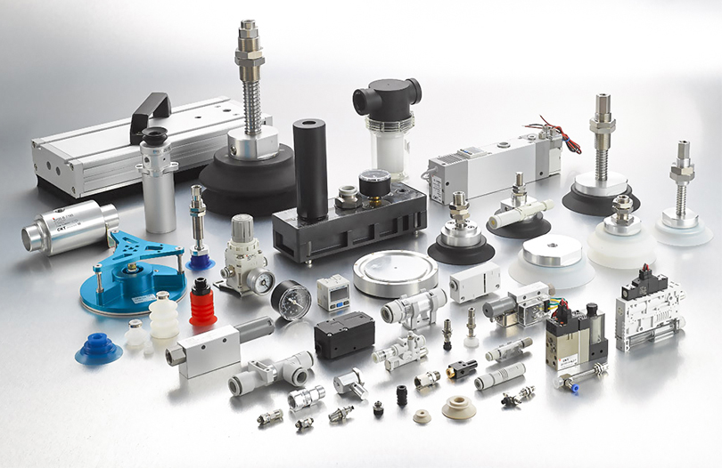
Vacuum systems grip workpieces using negative pressure instead of physical clamps, which makes them ideal for porous, fragile, flexible, or non-magnetic materials. A vacuum circuit has two main parts: a vacuum generator that creates the negative pressure, and a suction cup that contacts the workpiece.
Vacuum generators are classified as single-stage or multi-stage ejectors. A single-stage ejector produces a higher maximum vacuum level, often around -85 to -90 kPa, with high suction speed. A multi-stage ejector produces slightly lower vacuum, around -60 to -80 kPa, but consumes less air and creates a softer pickup action, making it better for thin films, porous cardboard, and lightweight parts. Some multi-stage units are also available as vacuum conveyors for moving granules or powders in bulk.
Suction cup force follows the same pressure-times-area relationship as cylinders: at -60 kPa, a 32 mm diameter flat cup has a theoretical holding force of about 48 N. With a safety factor of 2 for horizontal lifting and 4 to 8 for vertical lifting, that cup can safely carry roughly 24 N horizontally and 12 N or less vertically. Always calculate with the lowest vacuum level the system can produce, not the rated maximum, because leaking workpieces and worn cups reduce effective vacuum.
| Workpiece condition | Recommended cup type | Example series |
|---|---|---|
| Rigid flat surfaces | Flat cup with buffer | ZP series |
| Flexible packaging bags | Multi-fold bellows cup | CBLP series |
| Porous or uneven surfaces | Multistage ejector with larger bellows | CT series generator |
| Scratch-sensitive surfaces | Non-contact or no-mark cup | CTB, PEEK series |
| Confined or short-pick spaces | Short flat cup with adapter | ZP small-short series |
Do not forget the supporting vacuum hardware: a vacuum filter protects the generator and the suction line from dust and debris; a vacuum regulator keeps the suction gentle for fragile parts; a vacuum safety valve prevents a workpiece from dropping instantly when the generator is switched off; and a vacuum pressure gauge gives the operator a visible check of system health.
Fittings, Tubing, Silencers, and Buffers: The Supporting Cast
The smallest parts in a pneumatic system often cause the largest share of field failures. A leaking one-touch fitting, a crushed PU tube, or a failed silencer can stop a production line faster than a worn cylinder.
One-Touch Fittings and PU Tubing
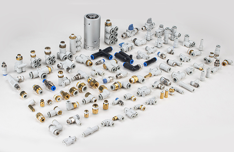
One-touch fittings let you push a tube in and pull it out without tools, which cuts assembly time on a multi-valve manifold dramatically. The standard brass or nickel-plated fitting suits dry shop air, while SUS316 stainless steel fittings are the right choice for wash-down areas, food processing lines, and corrosive atmospheres. PU tubing should be sized so the inner diameter does not restrict the flow required by the cylinder; a 6 mm outer diameter tube is common for small valves, while 8 mm, 10 mm, and 12 mm tubes serve larger cylinders.
Silencers and Hydraulic Buffers
Every solenoid valve exhaust port should have a silencer. A compact sintered silencer reduces exhaust noise to a safe level and also prevents dust and foreign material from entering the valve body. When a cylinder moves a heavy load at speed, the impact energy at the end caps must be absorbed: adjustable cushions handle moderate energy, and a hydraulic buffer is the better choice for high-speed or high-load applications because it provides a controlled deceleration curve.
- Keep tube runs short and straight.
- Use the minimum number of fittings and adapters between the F.R.L. and the actuator.
- Route tubing away from heat sources and sharp edges.
- Install silencers on every exhaust port and check them for clogging during routine service.
What to Check When Sourcing Pneumatics Components From a Manufacturer
For OEMs and maintenance teams, buying pneumatic parts from a supplier who actually manufactures them changes the risk profile. A manufacturer controls tolerances, lead times, and modification requests in a way that a pure trading company cannot. When evaluating a candidate manufacturer, check four things: product range, manufacturing depth, inventory strategy, and customization capability.
Zhejiang CKT Pneumatic is an example of a vertically integrated manufacturer. The company started in 2002 with the 4V solenoid valve series, expanded into quick connectors and throttle valves in 2005, added vacuum generators in 2007, suction cups and accessories in 2009, and reached mass production of multi-series cylinders in 2013. CKT reports a semi-finished parts warehouse with more than 20,000 part numbers, and states that over 90% of those parts are produced and machined internally. High internal production rates give the factory direct control over spool fit, seal grooves, cylinder bore finish, and surface treatment; these are the details that decide whether a valve seats cleanly and whether a cylinder glides without sticking. The company profile and history are documented on the CKT Pneumatic about page.
Use this sourcing checklist before you commit to a pneumatics component supplier:
- Product range: Can the supplier cover valves, cylinders, F.R.L., vacuum, and fittings from one catalog, or will you need multiple vendors?
- Manufacturing depth: Does the supplier machine critical parts in-house, or only assemble bought-in components?
- Inventory and lead time: Ask for actual stock coverage on the series you plan to order, especially for cylinders with non-standard stroke lengths.
- Technical support: The supplier should be able to give you flow data, force data, and installation instructions rather than a catalog page.
- Customization: For OEM projects, confirm whether the factory can make special rods, special seals, custom port positions, and private-label marking.
Frequently Asked Questions About Pneumatics Components
What is the difference between a 5/2 and a 5/3 solenoid valve?
A 5/2 valve has five ports and two positions, so it switches the actuator between one state and another. The center position of a 5/3 valve gives a third state, typically closed-center to hold the cylinder position, exhausted-center to let it float freely, or pressurized-center to push the cylinder out while the machine is in a stop state.
How do I calculate the cylinder force I actually need?
Calculate the theoretical force using F = P x A, then apply a load ratio of 50 to 70% for horizontal motion and 30 to 50% for vertical motion. Include the weight of the workpiece, the moving parts, and any external load, then add at least 20% margin for pressure fluctuation and seal friction.
What size F.R.L. unit do I need for a small automation machine?
Add the air consumption of all components that operate at the same time, then select an F.R.L. whose rated flow is 1.5 to 2 times the peak demand. A machine with four to six small cylinders typically works well with a G1/4 unit rated around 1500 to 2500 L/min.
Can one vacuum generator run multiple suction cups?
Yes, one generator can feed several suction cups, but the total leakage of all cups must stay low enough for the generator to reach the required vacuum level. Porous workpieces or damaged cups increase leakage and reduce the holding force on every cup, so size the generator for the worst case and use a larger-diameter generator or multiple generators when handling porous materials.
How often should the F.R.L. filter be drained?
In humid environments, drain the bowl daily or install an automatic drain. Watch the bowl level during the first week after installation to learn the actual condensation rate on your air system; if the bowl fills quickly, check the air dryer rather than assuming the filter is defective.
When are stainless steel one-touch fittings necessary?
Use SUS316 stainless fittings when the machine is washed down with chemicals, installed in a corrosive atmosphere, or used in food and pharmaceutical lines where surface contamination is a concern. For dry shop air in a normal factory environment, standard nickel-plated brass fittings give long life at a lower cost.