

 中文简体
中文简体
 English


Content
- 1 Pneumatic Automation Equipment: The Systems View
- 2 Air Preparation: F.R.L. Units as the First Line of Defense
- 3 Directional Control: Solenoid Valves and Selection Criteria
- 4 Actuation: Air Cylinders for Reliable Motion
- 5 Vacuum Automation: Generating and Applying Vacuum for Part Handling
- 6 Matching Pneumatic Components to Common Automation Tasks
- 7 Key Technical Parameters That Drive Procurement Decisions
- 8 Installation and Maintenance Practices That Prevent Downtime
- 9 FAQ
- 9.1 How do I choose the right pneumatic automation equipment for my machine?
- 9.2 Why does my pneumatic automation equipment run slow and unreliable?
- 9.3 How often should pneumatic components be replaced in industrial settings?
- 9.4 What is the difference between single-stage and multistage vacuum generators?
- 9.5 How can I reduce compressed air consumption in a pneumatic system without cutting performance?
A high-speed assembly cell that runs fine one week and starts losing cycle time the next is rarely experiencing a cylinder failure. More often, the problem is hidden in an undersized filter regulator, a leaking fitting, or a solenoid valve that was never rated for the duty cycle. The performance of pneumatic automation equipment depends on every component in the air path working together, from the compressor outlet to the end effector. If the specification of any single element is wrong, the cost is not immediate; it shows up over months as slower cycles, higher air consumption, and unpredictable downtime. Selecting pneumatic components with a systematic approach, instead of replacing parts one by one, is the fastest way to make a line more reliable.
This guide is based on insights from 23 years of pneumatic component manufacturing at CKT Pneumatic, where more than 20,000 semi-finished parts and 90 percent in-house processing provide direct exposure to the real-world behavior of valves, cylinders, vacuum generators, and air preparation units. We answer three questions: what makes a pneumatic system reliable, which components matter most for each application, and how procurement teams can avoid the mistakes that lead to premature maintenance.
Pneumatic Automation Equipment: The Systems View
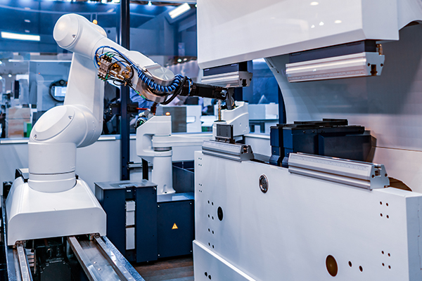
Compressed air travels a long way before it does work. It leaves the compressor, cools in an aftercooler, gets filtered, passes through a pressure regulator, receives lubrication, reaches a directional control valve, travels through tubing, and only then enters an actuator. The performance envelope of the whole line is determined by the weakest link in that chain. A 50 mm bore cylinder can push with enough force, but if the pressure regulator is not sized correctly, the pressure drop under load will make the stroke sluggish. An efficient solenoid valve is irrelevant if the filter is clogged, because the valve will not get enough air volume.
| Module | Typical Components | Performance Impact |
|---|---|---|
| Air preparation | Filter, regulator, lubricator | Prevents contamination, maintains stable pressure, controls lubrication |
| Directional control | Solenoid valves, air valves, manual valves | Determines response speed and cycle reliability |
| Actuation | Cylinders, grippers, rotary actuators | Converts pressure into mechanical motion and force |
| Vacuum handling | Vacuum generators, suction cups, vacuum filters | Enables non-destructive part picking and placement |
| Accessories | Fittings, silencers, tubing, buffers | Influences leak rate, noise, and component wear |
The systems view helps in one practical way: when a fault appears, the cause is often one module away from the symptom. If the gripping force on a vacuum line weakens, the problem could be in the vacuum generator, in a clogged vacuum filter, or in a worn suction cup. Replacing only the cup without checking the upstream pressure is the most common source of repeat failures on automated lines.
Air Preparation: F.R.L. Units as the First Line of Defense
According to ISO 8573-1, the international standard for compressed air quality, compressed air is classified by solid particulate concentration, water content, and oil content. Most arbitrary industrial compressed air systems deliver air with particle sizes that can damage seals over time. Undried air entering a cylinder or solenoid valve creates condensation inside metal cavities, leading to rust and sticking spools in frozen environments or standard factory settings. Lubricators add oil mist to reduce friction, but the correct lubricant and flow rate matter.
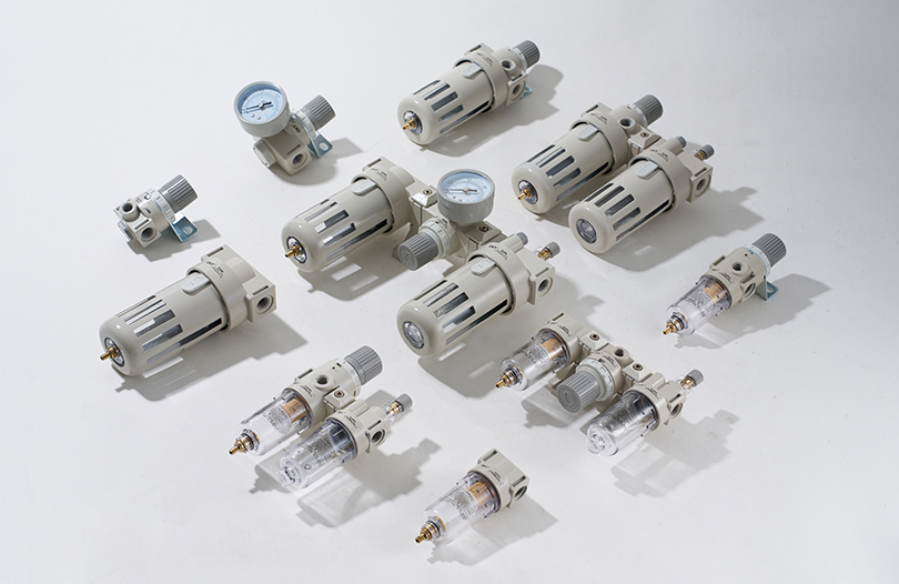
A well-selected F.R.L. unit acts as the first line of defense. The filter protects downstream components from dust, rust, and condensation. The regulator maintains the pressure level at which the actuator was designed to perform. The lubricator ensures that moving parts inside valves and cylinders receive a controlled oil mist. Each of these functions contributes to a simple outcome: consistent performance over millions of cycles.
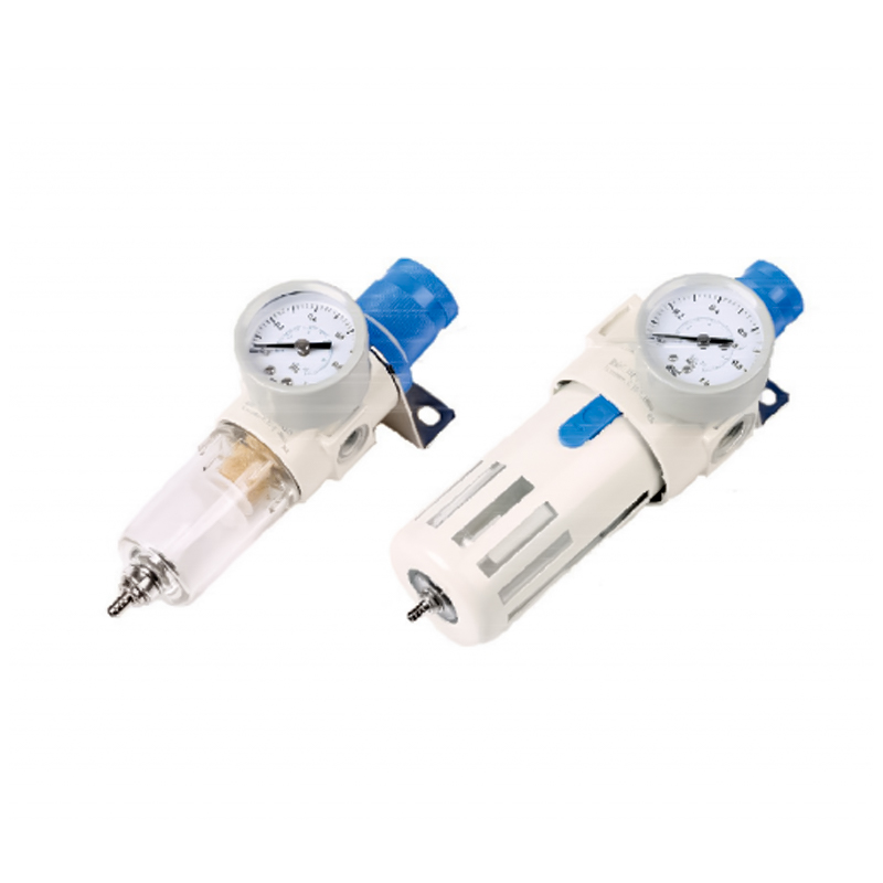 AFR/BFR Series Pressure Regulating Filter for Reliable F.R.L. SelectionThis compact filter regulator features small pressure loss and high water separation, with a self-locking mechanism to maintain set pressure. Its wide adjustment range supports matching downstream flow and pressure requirements.View Product →
Selection points for F.R.L. units are often misunderstood. Flow rate is the first parameter to check. A filter regulator that is too small causes excessive pressure drop when the system is at full demand. A standard guide is to size the F.R.L. at least 20 percent above the sum of flow requirements of all downstream actuators running simultaneously. The pressure regulation range should also match the machine's working pressure. For a line running at 0.5 MPa, the regulator should have an adjustment range broader than the required value so the set point does not sit at the extreme end of its span.
- Filter pore size: 40 μm is common for general purpose; 5 μm is used for precision or high-cycle machines.
- Regulator sensitivity: better models maintain stable pressure under dynamic flow changes.
- Lubricator: the drip rate must be adjustable per cylinder size and cycle frequency.
A common mistake is placing the F.R.L. too far from the distribution manifold. Long distances between the regulator and directional valve increase pressure lag and cause inconsistent cylinder speeds. The closer the F.R.L. is to the work area, the more precisely the pressure is controlled.
Directional Control: Solenoid Valves and Selection Criteria
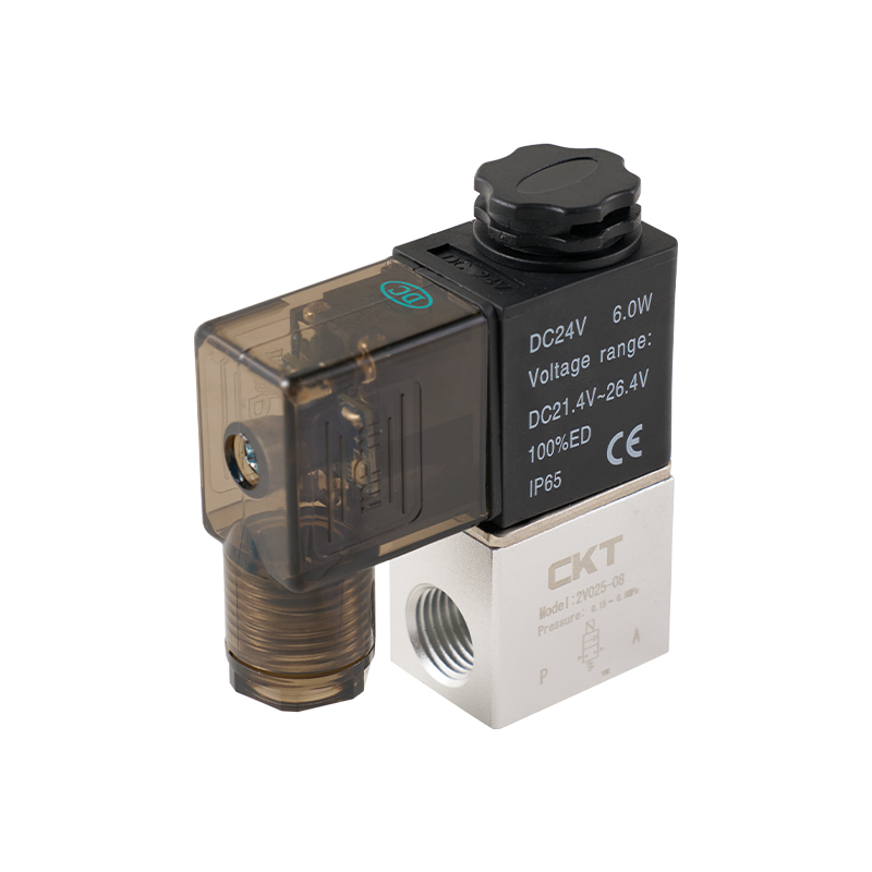
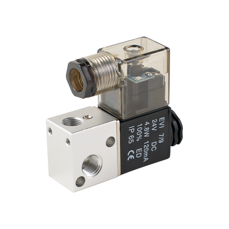
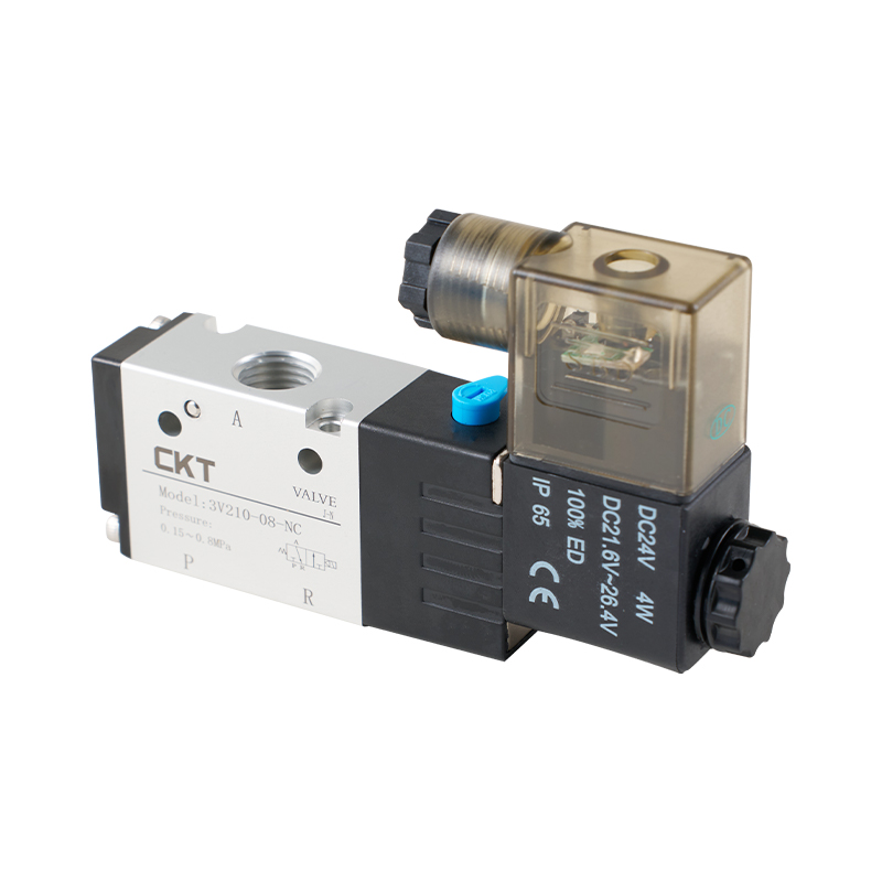
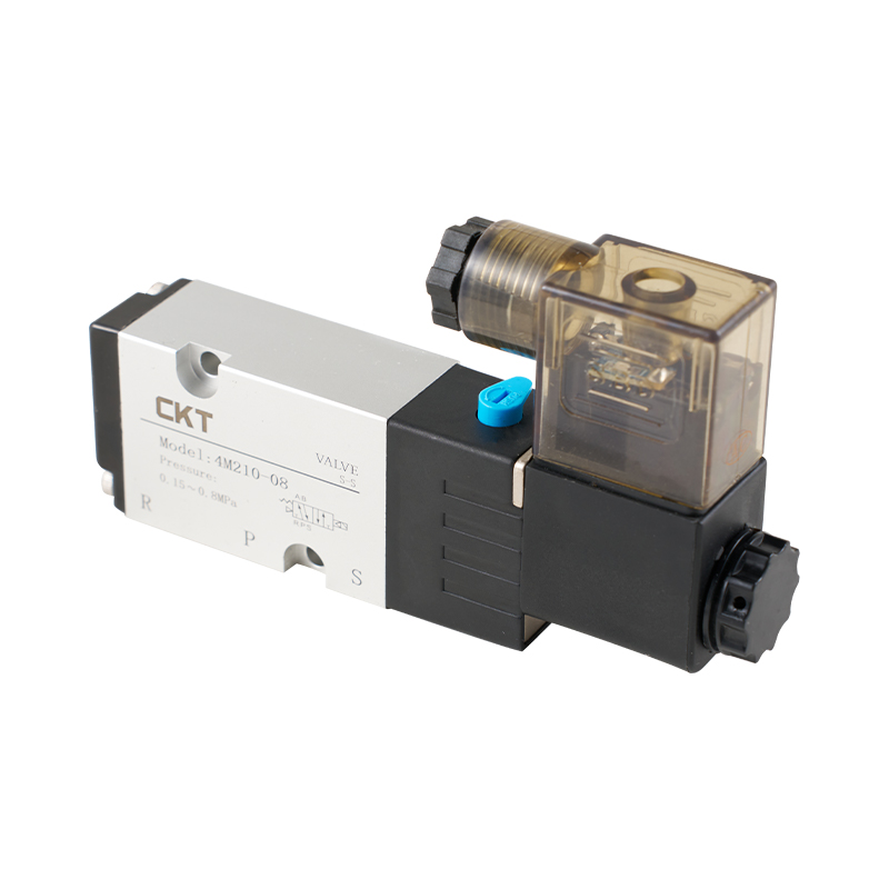
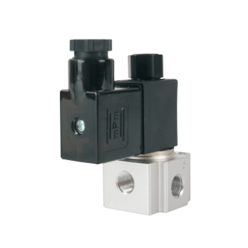
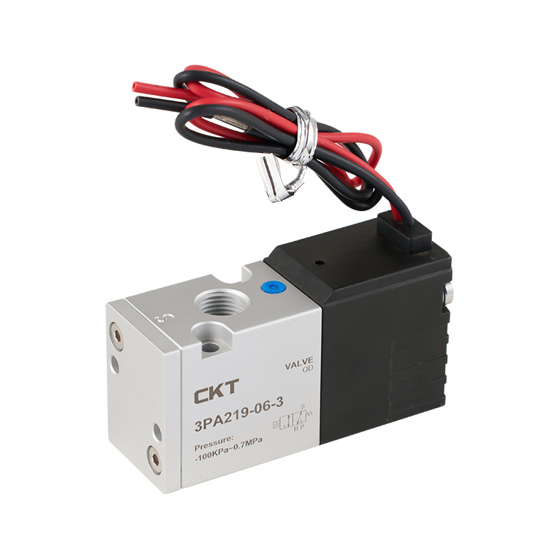
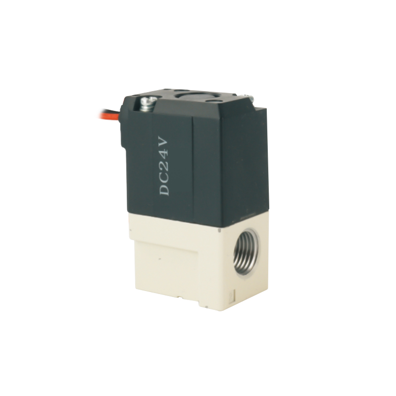
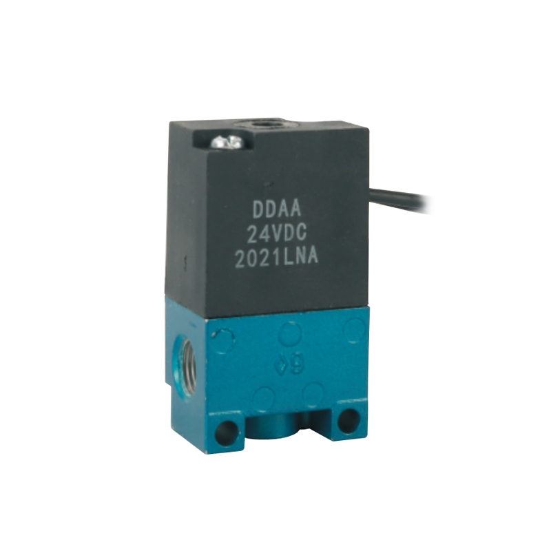
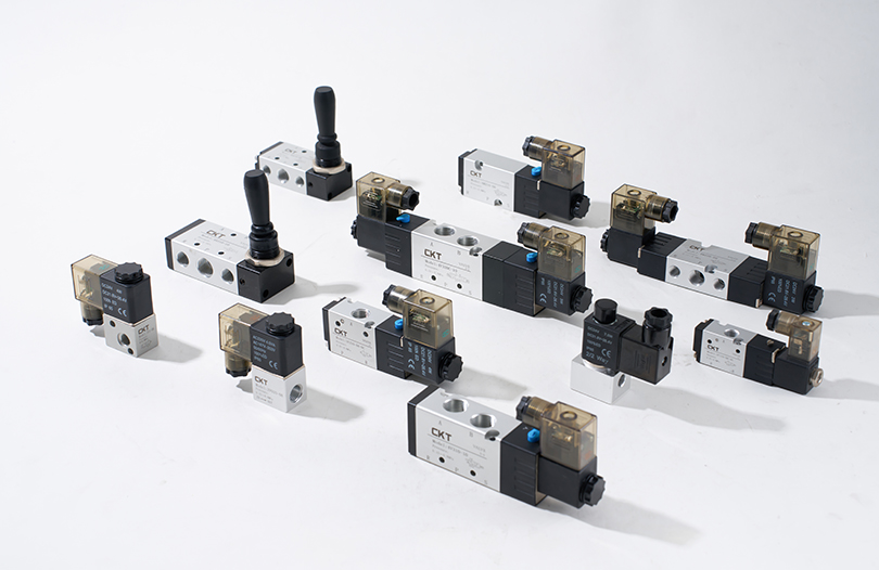
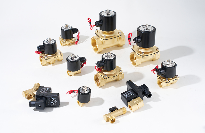
Directional control valves dictate how fast a cylinder responds and how long it holds its position. The two basic constructions are direct-acting and pilot-operated. Direct-acting valves move the spool or plunger with a solenoid and usually have lower response time for small-flow applications. Pilot-operated valves use a pilot signal to move the main spool, which allows higher flow rates without excessive coil power consumption.
The most important specification is the Cv factor (flow coefficient). A higher Cv means the valve can pass more air at a given pressure drop. If a cylinder requires a certain flow to reach the target speed, choosing a valve with too low a Cv caps the maximum stroke speed. For example, a 32 mm bore cylinder with a 100 mm stroke at 0.6 MPa can complete a cycle quickly with a valve rated at Cv 0.35, but if the Cv drops to 0.2, the stroke time may increase by 30 to 40 percent under the same operating conditions.
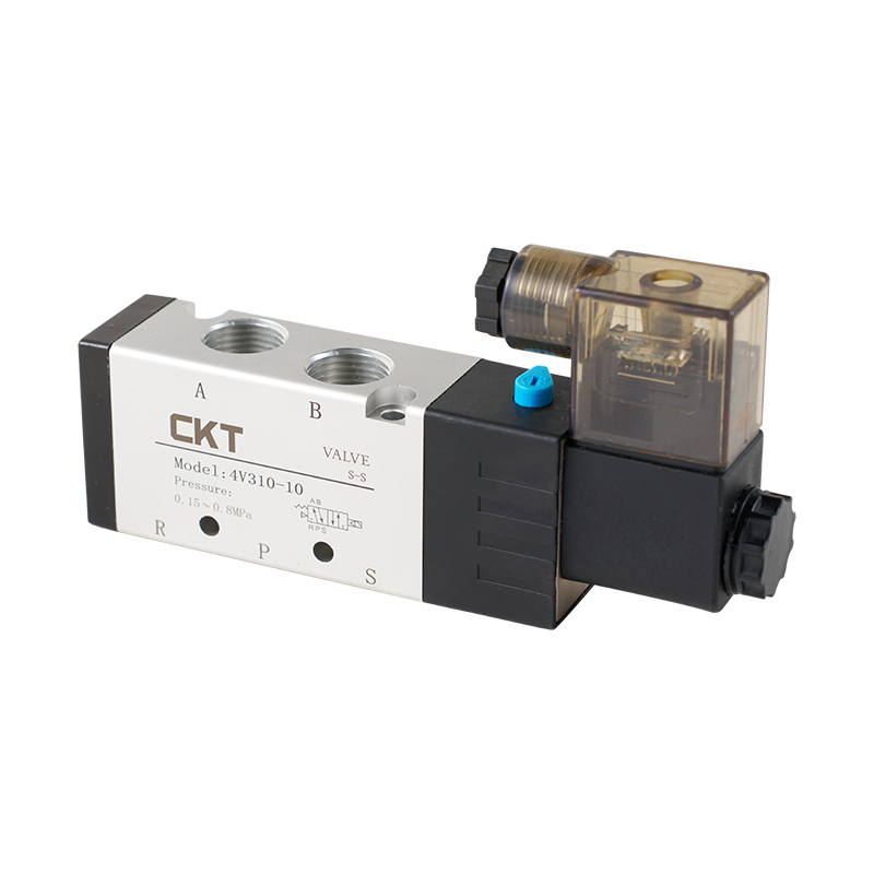
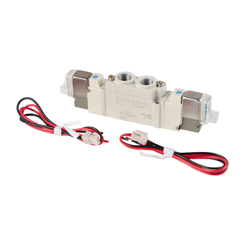
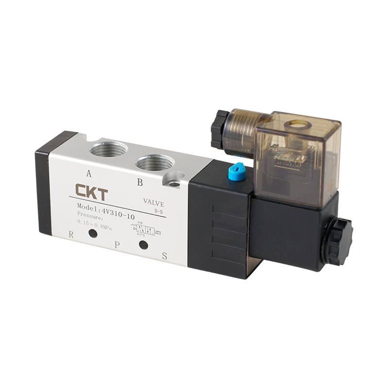 4V Series Pilot Operated 5-Way Solenoid Valve with High Flow and Fast ResponseThe 4V series offers a sliding column seal for low leakage and dynamic response, with optional three-position central functions. Its Cv ratings and quick actuation make it suitable for precise cylinder control.View Product →
Response time is another decisive factor in high-cycle machines. Solenoid valves in pneumatic applications typically respond within 5 to 20 milliseconds, depending on voltage, coil wattage, and internal flow path. In devices that run continuously at three cycles per second, the difference between a 10 ms and a 25 ms response time changes the available duty cycle margin. If the mechanism design was calculated for a shorter response time but the valve is slower, the machine may not reach the expected throughput. That is why CKT recommends validating valve response and flow together with cylinder sizing before purchasing.
| Parameter | Recommended Range | Why It Matters |
|---|---|---|
| Cv factor | 0.1 to 1.5 depending on actuator size | Defines maximum flow and, therefore, maximum speed |
| Response time | 5 to 20 ms | Directly influences cycle time for handling equipment |
| Voltage and wattage | DC24V common; AC110/220V available | Affects energy consumption and coil heat buildup |
| Protection class | IP40 or higher for clean rooms, IP65 for wet areas | Prevents unpredictable failures in harsh environments |
Installation quality also affects valve performance. A loose electrical connection or a strain-relief failure causes intermittent coil operation that is notoriously difficult to diagnose. Similarly, a missing muffler on the exhaust port increases noise and can draw dust back into the valve's internal spring chamber, accelerating spool wear.
Actuation: Air Cylinders for Reliable Motion
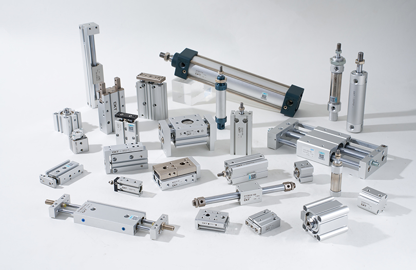
Air cylinders are the working arm of pneumatic automation. The selection starts with the bore size, which defines the force produced. Force is calculated as the working pressure multiplied by the piston area. At 0.5 MPa, a 32 mm bore cylinder generates a force of about 402 N in the pushing direction. A 50 mm bore cylinder produces about 981 N at the same pressure. If the load is 600 N, a 32 mm bore cannot do the job, even though the theoretical force seems close; friction, de-rating for high speed, and valve flow losses all reduce the effective force by 10 to 30 percent.
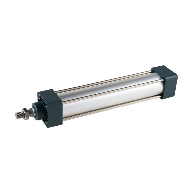 SC Series Tie Rod Standard Cylinder with Compact Design and Adjustable CushioningThis tie-rod cylinder provides reliable force output across bore sizes, with stable cushioning and high-temperature seals. Its speed range and compact length accommodate varied stroke requirements efficiently.View Product →
Stroke length must match the movement distance, but the stroke should never exceed the requirement unnecessarily. The longer the stroke, the more compressed air is consumed per cycle and the more the rod is exposed to side-load and buckling risk, especially in tie-rod designs. Air cylinder manufacturers generally provide a maximum allowable piston speed for each bore size. For example, standard cylinders may operate reliably at speeds up to 500 mm/s, while thin-body cylinders or special guide-rod cylinders may have different limits. Exceeding the rated speed causes premature wear on seals and can create excessive cushioning impact at the end of stroke.
Cylinder Types and Application Fit
The basic distinction is between standard tie-rod cylinders, which are robust and easy to mount with multiple position options; thin cylinders, which fit into compact spaces; and rodless cylinders, which save space in long-stroke moving applications. Multiaxis cylinders such as CXS serve as combined double-cylinder actuators for shorter stroke pick-and-place units. Pneumatic grippers, including parallel and cam-type units, are specialized cylinders with two opposing jaws for part clamping.
- Standard cylinders like the SC series provide the widest choice of mounting options and are the workhorse of machine building.
- Thin cylinders are recommended when vertical space is limited but side-loading is minimal.
- Rodless cylinders are selected when stroke length exceeds two times the space available for a conventional cylinder.
- Grippers are used in automotive and electronics assembly for reliable part holding.
Cushioning is an important selection point. A cylinder that slams at the end of shock absorbs mostly in the mechanical structure, causing component fatigue. Standard cylinders with adjustable cushion valves allow the engineer to softening the end-of-stroke impact. In a machine running at 60 cycles per minute, the cushioning force can mean the difference between a maintenance interval measured in years versus months.
Vacuum Automation: Generating and Applying Vacuum for Part Handling
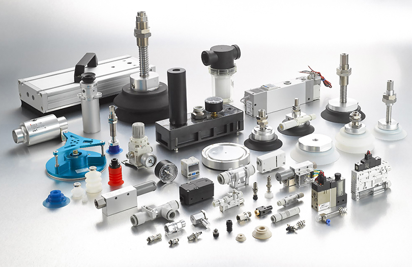
Vacuum components serve a unique role in the list of pneumatic automation equipment. Instead of pushing parts, they lift, hold, and release parts using differential pressure. Standard vacuum generators are self-contained units that use an air supply to create vacuum by the Venturi effect. They are compact, inexpensive, and reliable for small parts. Multistage vacuum generators produce higher vacuum and use less air than single-stage units, making them valuable for closed-loop conveying or handling porous materials.
Selecting a vacuum generator starts with the required vacuum level and suction flow. A vacuum level of -20 to -40 kPa is sufficient for holding flat, rigid parts like metal sheets or glass panels. Porous materials such as cardboard can hold only a partial vacuum, requiring a higher suction flow on the generator to compensate for leakage. A smooth rigid surface may reach -80 kPa or more, but the suction flow only needs to be moderate. The wrong combination of vacuum level and suction flow leads to constant relay stop failures during operation.
Suction cups also play a critical role. Bellows-type cups conform to curved surfaces, such as flexible packaging bags. Flat cups are best for rigid smooth surfaces. Special sponge cups are designed for textured or uneven surfaces where a regular cup would leak. Non-contact cups are specified for sensitive materials to prevent contact marks. For packaging machine operators, choosing a cup that does not match the surface profile results in weak holding force and frequent dropped parts. CKT's CBLP series, for instance, is specifically designed with multi-fold corrugated cups for flexible packaging bags.
Vacuum filters and check valves are important supporting components. The filter keeps dust out of the vacuum generator, extending its service life. A vacuum regulator adjusts the vacuum level to protect thin or fragile parts from over-suction. A vacuum safety valve can instantly release the vacuum when the system is shut down or when a part is transferred, improving cycle speed and preventing damage.
Matching Pneumatic Components to Common Automation Tasks
Engineering teams often ask whether a standard cylinder is enough, or whether they need a rodless cylinder or a servo-controlled actuator. The answer depends on the machine cycle and the physical constraints of the frame. In a packaging line, a compact F.R.L. and a solenoid valve with a simple mini-cylinder might work better than a large bore cylinder because the required stroke is short and the space is tight. In a sorting or inspection system, a mechanical valve triggered by an actuator can be used to start a sequence, but a solenoid valve connected to a PLC is usually preferred for flexibility.
| Application | Core Components | Selection Focus |
|---|---|---|
| Part picking and placement | Grippers, vacuum generator, suction cups | Payload, surface contact, response speed |
| Material conveying | Vacuum conveyor, multistage ejectors | Air consumption, vacuum flow, material porosity |
| Box closing and pressing | Standard cylinders, F.R.L., 4-way valves | Force, stroke, side-load resistance |
| High-speed sorting | Compact valves, high-frequency cylinders | Response time, cycle rate, cushioning |
| Clamping and holding | Mechanical valves, gripping cylinders, air filter | Clamping force, repeatability, safety |
Key Technical Parameters That Drive Procurement Decisions
Procurement decisions in pneumatic automation equipment should never be made on price alone. Several technical parameters have a direct impact on lifecycle cost, and understanding them helps avoid poor choices that show up as maintenance burden after the warranty expires.
Pressure Range and Operating Point
Standard pneumatic components are designed to operate within a pressure range of 0.1 to 0.8 MPa, with most machines set at 0.5 to 0.7 MPa. If a regulator is set at 0.5 MPa, components must show consistent behavior at that point. A valve rated for 0.05 to 1.0 MPa for pilot pressure is often a practical choice for industrial lines, since it tolerates pressure fluctuations across shift changes. In vacuum systems, the pressure range in kPa is more relevant. Vacuum generators should be matched to the system's worst-case vacuum demand.
Response Time and Cycle Rate
High-cycle equipment requires a response time that supports the target cycle rate. For a machine running 40 cycles per minute, total cycle time is 1.5 seconds. The valve response may only be 10 milliseconds, but if the cylinder takes 600 milliseconds to move 150 mm and the machine needs a 300 ms dwell, the math leaves only 590 milliseconds for the remaining motions. If the component response is slower than design, the machine has no buffer and will fail under peak demand.
Air Consumption and Energy Efficiency
Energy efficiency for pneumatic systems is often defined by the amount of compressed air consumed per cycle. A cylinder with a longer stroke consumes more air. A leakage rate of just 1 mm in a fitting can raise air consumption by thousands of liters per year. Measuring air consumption per machine cycle is an overlooked but effective tool for reducing operating costs. In factories with thousands of cycles daily, choosing well-sealed components and correctly sized cylinders saves far more than the savings from using a lower-priced supplier.
Service Life and Wear Rate
Pneumatic valves are often rated in millions of cycles. A high-quality solenoid valve may provide 10 million cycles, while a heavily loaded cylinder seal may need replacement after 2 to 5 million strokes. The environment is a key variable: dusty, humid, or chemically aggressive air drastically shortens component life. A simple change to a filtration unit or an upgraded seal material can add thousands of hours of runtime.
Installation and Maintenance Practices That Prevent Downtime
Correct installation has as much influence on service life as component quality. The first step is verifying that the compressed air is adequately dried and filtered before it enters the machine. The pipeline should be flush-cleaned before any pneumatic accessory is attached. Residual debris from the pipe is the primary cause of blocked silencers and sticking spools. In accordance with typical industrial maintenance practice, the air filter elements should be inspected every 4000 operating hours or sooner if the pressure drop across the filter becomes noticeable.
Seal compatibility is another point that is overlooked. The temperature of the compressed air and the presence of oil mist can make rubber seals swell, shrink, or crack. Checking that the seal material is compatible with the operating temperature range is essential. At CKT, the internal production practice is to test seals under a 100 percent in-house assembly process, giving high visibility into how seals behave in controlled manufacturing conditions.
Routine maintenance should include checking the cylinder cushioning adjustment, cleaning exhaust mufflers, and verifying that magnetic switches haven't shifted their mounting position. In many factories, a simple repositioning of the switch delays are the root cause of the machine losing one or two strokes per minute. An acoustic leak check using a soap solution or a modern ultrasonic detector can identify leaks in couplings, which are the single largest source of wasted energy in pneumatic plants.
When cylinder reliability becomes critical, the topic of cylinder installation and alignment comes up. Misalignment between the cylinder axis and moving load can reduce the actual service life to just a fraction of the designed life. Understanding the hidden costs of improper cylinder installation is more important than choosing the highest-priced cylinder.
FAQ
How do I choose the right pneumatic automation equipment for my machine?
Start by defining the task: moving, gripping, pressing, lifting, or sorting. Define the load weight, stroke length, required speed, available operating pressure, cycle rate, and environmental conditions. From those criteria, calculate the required bore, choose a solenoid valve with adequate Cv, and select an F.R.L. sized for the total flow. For vacuum handling, choose a generator that provides the needed vacuum level and suction flow, then match the cup type to the part surface. With this sequence, components are selected based on measurable machine requirements rather than preference.
Why does my pneumatic automation equipment run slow and unreliable?
In most cases, the cause is a combination of pressure drop and inadequate flow. An undersized F.R.L. or a partially clogged filter is the top culprit. A solenoid valve that is too small limits the air flow to the cylinder, slowing stroke speed. Leaking fittings and worn seals also cause a gradual pressure loss. Check the pressure at the cylinder inlet and compare it to the pressure at the regulator station; a drop of more than 0.02 to 0.05 MPa is worth investigating.
How often should pneumatic components be replaced in industrial settings?
Replacement intervals depend on cycle count, operating pressure, air quality, and load conditions. In high-cycle machines, solenoid valves are often inspected after 5 million cycles. Cylinder seals may need attention after 3 to 5 million cycles in continuous operation. Filters generally require element replacement every 4000 to 8000 hours, depending on contamination. The most reliable approach is to track the cycle count and replace key components at the end of their useful life, rather than waiting for a complete failure.
What is the difference between single-stage and multistage vacuum generators?
Single-stage generators are compact and deliver moderate vacuum with simply designed internal nozzles. They are commonly used for small parts in pick-and-place applications. Multistage generators have multiple nozzles in series or parallel, producing higher vacuum and more suction flow at a lower compressed air consumption per unit of vacuum. These are specified for porous materials, longer suction lines, or applications where multiple cups are supplied as a group.
How can I reduce compressed air consumption in a pneumatic system without cutting performance?
Reduce operating pressure to the lowest acceptable level, since air consumption is proportional to absolute pressure. Choose cylinders with the minimum necessary stroke length. Use vacuum generators with multistage design where high vacuum is needed. Eliminate leaks by maintaining couplings and fittings. Check the F.R.L. for pressure drop and the lubricator for excess oil flow. In many cases, simply fixing leaks can cut air consumption by 20 to 30 percent, without changing any process parameters.