

 中文简体
中文简体
 English


Content
- 1 What Is a Pneumatic Cylinder Actuator?
- 2 Main Types of Pneumatic Cylinder Actuators
- 3 Critical Selection Criteria for Cylinder Actuators
- 4 Force Calculation and Sizing with Real Numbers
- 5 Mounting Options and Installation Considerations
- 6 Pneumatic Cylinder Applications Across Industries
- 7 Maintenance Practices That Extend Actuator Life
- 8 Why Choose the Right Cylinder Manufacturer
- 9 Frequently Asked Questions
- 9.1 What is the most common failure mode of a pneumatic cylinder actuator?
- 9.2 How do I choose between a standard, thin, or rodless cylinder?
- 9.3 How much safety factor should I add when sizing a cylinder?
- 9.4 Can a pneumatic cylinder actuator be used for precise positioning?
- 9.5 What is the difference between single-acting and double-acting actuators?
- 9.6 How do I calculate the air consumption of a cylinder?
- 9.7 When should I use a rodless cylinder instead of a standard cylinder?
- 9.8 What determines how fast a cylinder can move?
- 9.9 What repairs are typically needed for a pneumatic actuator?
Pneumatic cylinder actuators are the most widely used linear motion devices in industrial automation, and the correct choice matters more than most engineers expect. Selecting the wrong bore size or mounting style leads to cycle time losses, premature seal wear, and higher energy consumption. This guide provides a decision framework that covers force calculations, stroke selection, cylinder types, mounting configurations, and practical maintenance considerations. Use the included charts and formulas to size your next actuator with confidence.
What Is a Pneumatic Cylinder Actuator?
A pneumatic cylinder actuator is a mechanical device that uses the energy of compressed air to produce linear pushing or pulling force. It consists of a cylindrical barrel, a piston that slides inside, a piston rod that extends from one or both ends, and sealing elements that maintain pressure. The actuator is the final motion element in a pneumatic system: the one that actually moves a load.
When air enters one chamber and the other opens to exhaust, the pressure differential pushes the piston. The rod that sticks out transmits this force to a machine part connected to it. In a double-acting cylinder, air drives the piston in both directions. In a single-acting cylinder, a spring returns the piston to the home position. This simple principle gives designers precise control over movement speed, force, and positioning in almost any manufacturing environment.
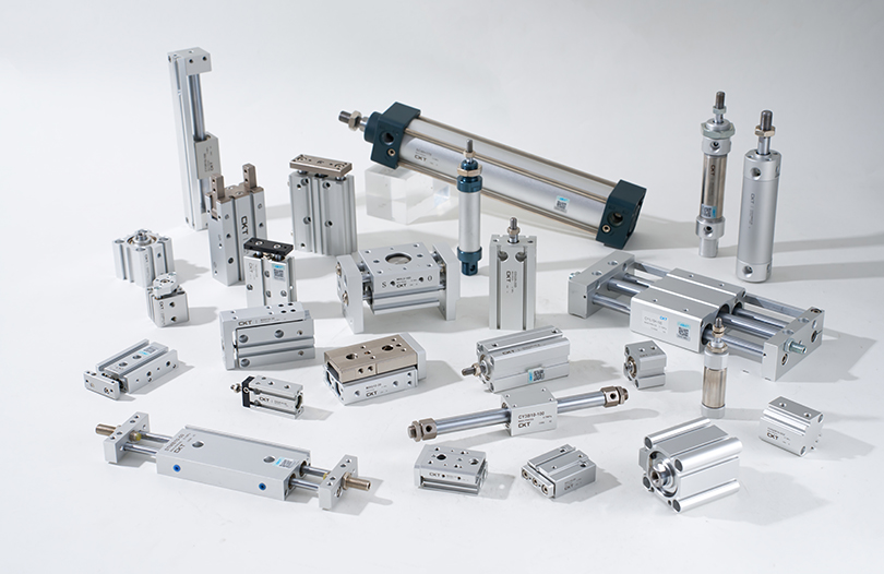
Manufacturers build cylinders in dozens of configurations to match specific load conditions. Standard tie-rod cylinders follow ISO 15552 dimensional standards. Thin cylinders fit into tight vertical spaces. Rodless cylinders offer long strokes with compact overall length. The right starting point is not the cylinder itself, but the load you need to move and the work envelope you have available.
Main Types of Pneumatic Cylinder Actuators
Choosing between cylinder categories comes down to stroke length, space constraints, and the type of motion the application demands. Here is a practical breakdown of the primary families.
Standard Tie-Rod Cylinders (SC Series Style)
Standard cylinders with tie rods are the workhorse of the industry. The pull-together design holds the end caps against the barrel with four threaded rods, making them simple to seal and maintain. These cylinders operate at pressures from 0.1 to 1.0 MPa and are available in bore sizes from 32mm to 200mm. A typical SC series cylinder with a 100mm bore and 200mm stroke produces roughly 7,850 N of theoretical force at 0.6 MPa. This capacity handles most conveyor pushers, clamping mechanisms, and machine tool applications.
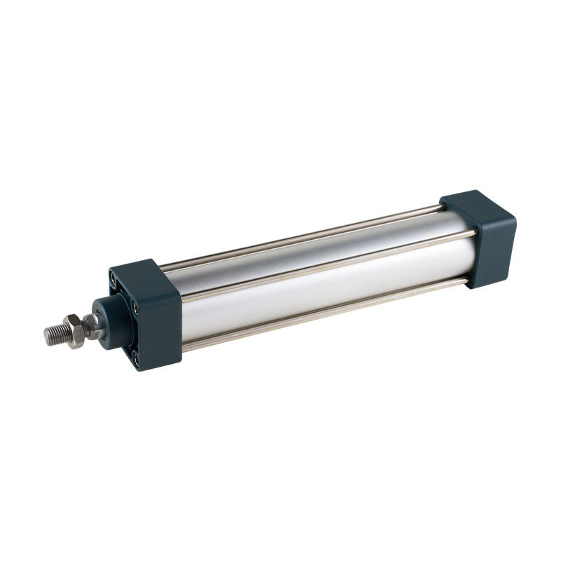 SC Series Tie Rod Type Standard Pneumatic CylinderThe SC series offers a reliable pull-together design with a compact length compared to ISO15552, making it a solid choice for conveyor pushers and clamping mechanisms needing standard bore sizes and adjustable cushioning.View Product →
Thin and Compact Cylinders (CQ2 Series Style)
Thin cylinders are engineered for fixture where mounting space is severely restricted. The body length is reduced substantially compared to standard cylinders. CQ2 series thin cylinders come in bore sizes from 12mm to 100mm and offer strokes up to 200mm, with a total body length as short as 34mm for a 20mm bore model. They are commonly used for clamping small parts, pressing components into housings, and activating gates in packaging lines. The mounting surface is typically the end cap itself, which simplifies integration into the assembly.
Rodless Cylinders (CY1L and MY Series)
Rodless cylinders use an internal or external carriage that travels along the barrel, eliminating the piston rod entirely. This design delivers stroke lengths equal to the barrel length, or even longer in some variants, with the overall footprint barely larger than the stroke itself. Magnetic-coupled rodless cylinders like the CY1L series offer smooth, leak-free operation without mechanical linkage penetration. A 50mm bore rodless cylinder with 500mm stroke fits in an envelope just slightly longer than 500mm, making it ideal for CNC machine tool covers, long-rail pick-and-place systems, and gantry-style transfer devices.
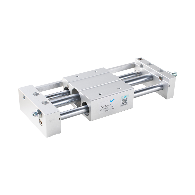 CY1L Series Magnetic Coupled Rodless Cylinder with Ball Bearing GuideThis space-saving rodless cylinder uses magnetic coupling to eliminate piston rod leakage, and its ball bearing slider provides smooth, torque-resistant motion for compact long-stroke applications.View Product →
Additional Specialized Types
- Mini cylinders (MA/MAL series) in bore sizes from 6mm to 32mm for light loads in compact machinery.
- Slide cylinders (MXH/MXQ series) with integrated linear guides for high-precision movement that resists side loads.
- Pneumatic grippers (MHZ2/MHL2) for robotic end-of-arm tooling to grasp and release parts.
- Rotary cylinders (MK series) that clamp and rotate in a single motion, used in welding jigs and indexing fixtures.
| Cylinder Type | Bore Range | Stroke Range | Best For |
|---|---|---|---|
| Standard (SC series) | 32–200 mm | 25–1000 mm | General automation, pushing, clamping |
| Thin (CQ2 series) | 12–100 mm | 5–200 mm | Tight spaces, short strokes |
| Rodless (CY1L) | 10–63 mm | 100–1000 mm | Long strokes, compact footprint |
| Mini (MA series) | 6–32 mm | 10–300 mm | Small assemblies, medical devices |
| Slide (MXQ series) | 6–63 mm | 10–200 mm | Precision parts feeding |
Critical Selection Criteria for Cylinder Actuators
The selection process is not a simple lookup table. Several variables interact and affect each other. The following criteria are arranged in the order you should evaluate them.
- Required force determines the minimum bore size at the available system pressure. Calculate the load force including acceleration and then add a 20–30% safety factor.
- Stroke length defines the distance the mechanism must travel. Extend the stroke beyond the exact requirement to allow capping and end-of-stroke cushioning.
- Available space decides whether a standard, thin, slide, or rodless cylinder fits. Measure the envelope in three dimensions.
- Operating pressure in your facility directly influences force output and, in turn, bore size. Typical factory air supplies are 0.4–0.7 MPa.
- Speed requirements dictate the necessary air flow rate and may require speed control valves or larger valve flow coefficients.
- Side load and alignment determine whether you need a guide, a slide cylinder, or additional external guides to prevent rod bending.
- Environment such as high temperature, dust, or moisture may require special seal materials or protective covers.
In a typical packaging machine at a food factory, the operating pressure is 0.5 MPa and the clamp force requirement is 500 N. Using a 50% safety factor, the target force becomes 750 N. The formula shows that a 50mm bore cylinder at 0.5 MPa produces 981 N of theoretical force, which leaves enough headroom. A 40mm bore would produce only 628 N, too low under these assumptions.
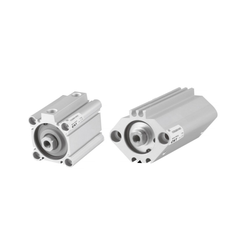 CQ2 Series Thin Cylinder for Compact Mounting SpacesWith significantly reduced body length and non-protruding magnetic switches, this thin cylinder fits where space is restricted, offering reliable operation in small clamping and pressing tasks.View Product →
Force Calculation and Sizing with Real Numbers
The theoretical force produced by a pneumatic cylinder is calculated using the piston area multiplied by the applied pressure. The formula is:
F (N) = P (MPa) × A (mm²)
Because 1 MPa equals 1 N per square millimeter, the calculation works directly in SI units. Here is a worked example:
Take a 63mm bore cylinder at 0.6 MPa operating pressure.
- Piston area: A = π × (63/2)² = π × 992.25 = 3,117 mm²
- Theoretical force: F = 0.6 × 3,117 = 1,870 N
- With 75% efficiency: usable force ≈ 1,402 N
The rod side of the cylinder produces a smaller force because the rod takes up part of the piston area. For a 63mm bore cylinder with a 20mm rod:
- Rod-side area: A = π × (63/2)² - π × (20/2)² = 3,117 - 314 = 2,803 mm²
- Rod-side force: F = 0.6 × 2,803 = 1,682 N
This difference of about 10% matters when force must be identical in both directions. In such cases, select the bore size based on the rod-side force requirement or use a multi-position cylinder to meet both needs.
Air consumption is the other key calculation. The volumetric flow rate is determined by multiplying the cylinder's swept volume by the number of cycles per minute. A 32mm bore cylinder with a 100mm stroke operates roughly 820 cm³ per single stroke, or 1,640 cm³ for a complete push-pull cycle. At 30 cycles per minute, the required flow is about 49 liters per minute at atmospheric conditions. Compressed air systems need to account for this demand when sizing compressors and flow regulators.
| Bore Size (mm) | Piston Area (mm²) | Theoretical Force (N) | Usable Force (N) |
|---|---|---|---|
| 16 | 201 | 100 | 80 |
| 32 | 804 | 402 | 322 |
| 50 | 1,963 | 982 | 785 |
| 63 | 3,117 | 1,559 | 1,247 |
| 80 | 5,027 | 2,513 | 2,011 |
| 100 | 7,854 | 3,927 | 3,142 |
These values are based on an industry-standard assumption of 0.5 MPa pressure and an 80% force efficiency factor. Always consult the manufacturer's data sheet for exact force output because seal friction varies between different models and piston materials.
Mounting Options and Installation Considerations
The way you mount a cylinder determines how it handles side loads, how it connects to the moving mechanism, and how easy it is to service. The main mounting styles are:
- Permanent flange mounting secures the cylinder body directly to the frame, ideal for fixed, stationary applications with clear axial alignment.
- Pivot mounting (clevis) allows the cylinder to angle during the motion, which is useful when the load path changes direction or when the actuator is connected to a lever.
- Rear eye mounting provides a hinge point at the back cap, allowing the cylinder to adjust its angle slightly during operation, reducing side loads on the rod.
- End cap mounting uses threaded holes on the front or rear cap, commonly found on thin and compact cylinders where space is limited.
- Side mounting with brackets clamps around the body, suitable for long cylinders where the mounting surface is continuous.
When a cylinder carries a significant side load, the recommended practice is to add external linear guides. A slide cylinder with integrated guide rods handles side loads better and maintains alignment. For example, MXQ series slide cylinders incorporate circulating bearings in a compact body, making them suitable for precision indexing applications where misalignment would otherwise cause the piston rod to bend and wear out seals prematurely.
Cushioning at both ends of the stroke reduces impact forces and extends actuator life. Standard cylinders in the SC and SE/SI series often include adjustable air cushioning. The cushioning valve restricts exhaust air at the end of the stroke, decelerating the piston. Without cushioning, a piston traveling at 300 mm/s hitting an end cap generates substantial mechanical shock. Adding a hydraulic buffer to the actuator or installing an external shock absorber further softens the impact on heavy loads.
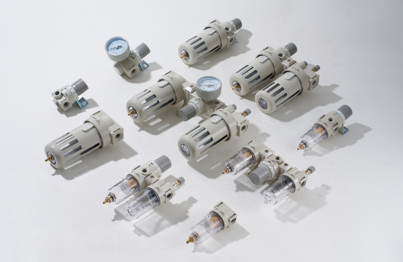
Air quality is equally important. Compressed air containing moisture or particulates damages seals and accelerates wear. A modular F.R.L air preparation unit placed upstream of the actuator removes water, filters solid particles, and lubricates moving seals. The modular F.R.L. unit line available from pneumatic component manufacturers is sized based on the total cylinder flow consumption, and selecting a filter with 5 μm or 25 μm rating is standard practice for most applications.
Pneumatic Cylinder Applications Across Industries
The versatility of pneumatic actuators comes from the wide variety of industries that rely on them for repetitive, high-speed, and reliable motion.
Packaging and Food Processing
In packaging lines, pneumatic cylinders push cartons onto conveyors, actuate sealing bars, and position fillers. Food processing environments often require stainless steel or coated cylinders to resist cleaning chemicals. CKT's stainless steel mini cylinders in the CJ2 and CM2 series are built for such washdown conditions. The cycle times in packaging typically range from 0.2 to 2 seconds, requiring quick exhaust valves and high-flow directional control valves to maintain speed.
Material Handling and Robotics
Automated storage and retrieval systems use rodless cylinders and slide actuators for horizontal movement of load-carrying platforms. In robotic applications, pneumatic grippers handle parts at high speeds, where the MHZ2-style parallel grippers offer precision and repeatability. The total stroke in end-of-arm tooling grippers is usually short, often only 10–30mm, but the cycle rates reach 60 to 120 operations per minute.
Machine Tools and Metal Cutting
CNC lathes and milling machines use pneumatic cylinders for clamping fixtures, engaging tool changers, and actuating drill heads. The forces required here are moderate to high, and the cylinders must withstand constant operation. A typical lathe chuck clamping system uses a 63mm bore cylinder at 0.6 MPa, providing roughly 1,700 N of clamp force, which is adequate for workpieces up to 100mm in diameter in most low-speed turning operations.
Vacuum Handling and Suction Systems
Pneumatic cylinders are often paired with vacuum generators for pick-and-place operations. The cylinder moves the vacuum suction cup into position, the vacuum generator activates to grip the workpiece, and the cylinder lifts and places it. This combined pneumatic-vacuum approach is visible across industries handling products from glass sheets to flexible packaging bags. In such systems, the cylinder's speed and stroke precision directly affect the vacuum cup's ability to maintain a reliable grip.
Maintenance Practices That Extend Actuator Life
Pneumatic actuators are robust, but they still require scheduled maintenance to perform at their best. The most common failure modes are seal wear, piston rod corrosion, and internal leakage caused by contaminated compressed air.
- Check for rod surface scratches every 2,000 operating hours. A scratched rod wears out seals quickly. Replace the rod or install a rod boot if the environment is abrasive.
- Inspect seals for cracking during routine maintenance. Nitrile seals typically last 3 to 5 years in normal conditions, but temperatures above 70°C reduce their life significantly. Use fluoroelastomer seals for hot environments.
- Monitor leak rates by listening for hissing noise near the rod or by applying soapy water solution. An internal leak past the piston seal reduces force output and wastes compressed air, increasing energy costs.
- Drain the moisture separator in the F.R.L unit daily to keep the air supply clean. Accumulated water inside the cylinder body causes the inner bore to rust, which destroys the piston seals in short order.
- Cushioning adjustments: tighten or loosen the cushion needle valves so that the piston decelerates smoothly in the last 10–20mm of stroke. Incorrect cushion settings cause a hard stop that can bend the rod or fracture the end cap.
A preventive maintenance schedule of 6 to 12 months is standard for pneumatic actuators operating in a typical factory environment. In higher-speed packaging lines running 24 hours a day, inspection intervals should be shortened to 3 to 6 months because the higher cycle count accelerates wear. Replacing seals during scheduled downtime is far more cost-effective than an unplanned machine stop in peak production.
Why Choose the Right Cylinder Manufacturer
Actuator quality varies significantly between suppliers, and the cost of a good cylinder versus a poor one goes far beyond the purchase price. A 60mm bore cylinder that fails in six months costs more in downtime and replacement labor than a quality cylinder that runs for years. Manufacturers with over two decades of manufacturing experience in pneumatic components have accumulated production knowledge that directly improves seal retention, rod plating thickness, and concentricity tolerances, all of which affect service life.
Zhejiang CKT Pneumatic Co., Ltd has been manufacturing pneumatic components since 2002. Their product portfolio includes more than 200 actuator models, covering pneumatic cylinders from standard ISO dimensions to compact thin and rodless types. A higher proportion of internally machined components, including the cylinder barrel and pistons, gives suppliers tighter control over fit and finish. This internal manufacturing capability creates consistency between batches, which is critical for machine builders who must replace actuators months or years later with matching dimensions and tolerances.
When selecting an actuator supplier, ask about:
- Bore and stroke standard availability without custom lead times
- Seal material options for your operating temperature range
- Cushioning adjustment details and cushion length specifications
- Rod surface treatment options for corrosion resistance
- Mounting hardware compatibility and availability from stock
- Multiple cylinder families from a single supplier to consolidate maintenance inventory
Frequently Asked Questions
What is the most common failure mode of a pneumatic cylinder actuator?
Piston seal wear is the most frequent failure mode. The seal degrades due to friction, high temperatures, and contamination in the compressed air. Symptoms include reduced force output, slower cylinder movement, and audible air leakage. Regular inspection and installing quality filtration upstream are the first lines of defense.
How do I choose between a standard, thin, or rodless cylinder?
Start by measuring the available mounting envelope. If space is unrestricted and you need high force, use a standard cylinder. If vertical space is limited and strokes are short, use a thin cylinder. If stroke length is long but overall machine footprint must stay small, use a rodless cylinder. The force requirement always comes first, and then the space constraint narrows down the option.
How much safety factor should I add when sizing a cylinder?
Industry practice is to add 20–30% to the calculated load force when selecting a bore size. This accounts for seal friction, air pressure fluctuations, and dynamic load increases from acceleration. For applications with intense side loading on the rod, or where the cylinder will be exposed to external forces, increase the safety factor to 40%.
Can a pneumatic cylinder actuator be used for precise positioning?
A standard pneumatic cylinder alone does not provide precise positioning because air is compressible and the piston position changes under load. For positioning tasks, use a cylinder with a magnetic piston in combination with a magnetic switch (reed sensor) to detect end positions, or use a slide cylinder with built-in guide rails and a servo mechanism via a proportional valve for intermediate positions.
What is the difference between single-acting and double-acting actuators?
A single-acting cylinder uses air to push in one direction and a spring to return. A double-acting cylinder uses air in both directions, providing more force control and less energy loss from spring back-pressure. For most industrial automation tasks, double-acting cylinders are preferred because they offer more balanced speed and force in both directions.
How do I calculate the air consumption of a cylinder?
Multiply the piston area by the stroke length to get the swept volume per stroke. For a complete cycle, the volume applies twice (extend and retract). Then multiply by the number of cycles per minute and by the ratio of operating pressure to atmospheric pressure. For example, a 32mm bore, 100mm stroke cylinder at 0.6 MPa requires about 35 liters per minute for 30 cycles per minute, plus a 20–30% allowance for leakage and line losses.
When should I use a rodless cylinder instead of a standard cylinder?
Choose a rodless cylinder when the stroke length is long relative to the available space and when the load requires support over the full travel distance. Rodless cylinders are common for long-stroke movement on gantry cranes, machine tool protective covers, and conveyors. Because there is no piston rod extending outside the body, the overall length remains compact, and the risk of rod buckling is eliminated.
What determines how fast a cylinder can move?
The speed of a pneumatic cylinder is limited by the air-flow capacity of the directional control valve and the speed control valve, plus the bore size and the pressure differential across the piston. Larger bore cylinders move slower than smaller ones with the same valve because they displace more air per unit of stroke. Installing a larger valve with a higher Cv coefficient, or using a quick-exhaust valve at the cylinder port, can increase the speed.
What repairs are typically needed for a pneumatic actuator?
The most common repair is replacing the piston seals and rod seals. This involves disassembling the cylinder, removing worn seals, cleaning the barrel, installing fresh seals, and reassembling. The tie-rod design makes this straightforward. Seals kits are available for most standard cylinder models, and replacing seals every 1 million cycles is a common preventive maintenance rule in high-cycle packaging and assembly operations.