

 中文简体
中文简体
 English


Content
- 1 What Actually Separates a Reliable Pneumatic Gripper Manufacturer From the Rest
- 2 How a Pneumatic Gripper Actually Converts Air Pressure Into Grip Force
- 3 Comparing the Four Gripper Types Manufacturers Commonly Produce
- 4 Material and Build Quality Factors That Determine Service Life
- 5 Where Pneumatic Grippers Are Doing the Heaviest Lifting Across Industries
- 6 Maintenance Practices That Extend Gripper Lifespan Beyond the Warranty Period
- 7 What to Verify Before Placing an Order With a Pneumatic Gripper Manufacturer
- 8 A Quick Reference Glossary for Gripper Specification Sheets
- 9 Frequently Asked Questions
- 9.1 What air pressure do most pneumatic grippers require to operate correctly?
- 9.2 How long do pneumatic grippers typically last before needing replacement?
- 9.3 Can pneumatic grippers hold a part if air supply is lost mid-cycle?
- 9.4 What is the difference between single-acting and double-acting pneumatic grippers?
- 9.5 How do I choose the correct bore size for a specific part weight?
- 9.6 Do pneumatic gripper manufacturers typically offer custom jaw finger machining?
- 9.7 How much air does a typical pneumatic gripper consume per cycle?
- 9.8 Can a pneumatic gripper be used in a washdown or food-adjacent environment?
- 9.9 What is the difference between jaw repeatability and jaw accuracy?
- 9.10 How do I know if I need a self-centering gripper instead of a standard parallel gripper?
- 9.11 What causes a pneumatic gripper to develop excessive jaw wobble over time?
What Actually Separates a Reliable Pneumatic Gripper Manufacturer From the Rest
The short answer: a dependable pneumatic gripper manufacturer is defined by three measurable things, not marketing copy — repeatable gripping force across thousands of cycles, sealed construction that resists dust and moisture ingress, and jaw stroke accuracy within 0.02mm to 0.05mm. Everything else — coating color, catalog thickness, or showroom size — is secondary. Buyers who search for pneumatic gripper manufacturers are usually trying to solve one of two problems: a gripper that wears out too fast on a high-speed line, or a gripper that cannot hold consistent force on parts with varying surface finish. Both problems trace back to design choices made at the manufacturing stage, which is why this guide focuses on what to check before placing an order rather than generic product descriptions.
Pneumatic grippers remain the most cost-effective end-of-arm tooling option for repetitive pick-and-place work, and demand has stayed strong into 2026 as electronics assembly, automotive sub-component lines, and packaging automation continue to expand. Zhejiang CKT Pneumatic Co., Ltd has built its catalog around this exact demand curve, producing parallel, angular, and three-jaw gripper lines aimed at OEM integrators who need consistent lead times as much as consistent performance.
How a Pneumatic Gripper Actually Converts Air Pressure Into Grip Force
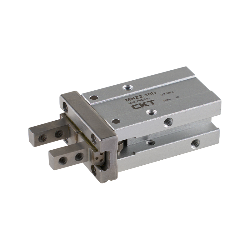
A pneumatic gripper is a mechanical actuator that converts compressed air pressure into linear or angular jaw movement through a piston-and-cam or piston-and-rack mechanism. Air enters one port, pushes a piston along a bore, and that piston motion is translated into jaw closing force through a mechanical linkage. The relationship is straightforward but often misunderstood by buyers comparing specification sheets:
The Core Components in Sequence
- Cylinder body — houses the piston and defines the bore diameter, which directly sets maximum theoretical force
- Piston and rod — the moving element that receives air pressure on one or both sides
- Cam or rack-and-pinion linkage — converts linear piston travel into jaw motion, either parallel or angular
- Jaw guides — linear bearings or dovetail slides that keep jaw travel free of lateral play
- Seals — the component most responsible for long-term reliability, since seal wear is the leading cause of force drop-off in the field
The formula integrators use to estimate theoretical gripping force is F = P × A × n, where P is supply air pressure, A is effective piston area, and n is the number of jaws in contact with the part. This number is always a ceiling, not a guarantee — real-world grip force drops by roughly 15% to 30% depending on friction losses in the linkage, which is exactly why two grippers with identical bore diameters can perform very differently depending on machining tolerance and linkage design.
Single-Acting Versus Double-Acting Circuits
Single-acting grippers rely on a compression spring to return the jaws to their default position, meaning air pressure only does work in one direction. This design is common on smaller bore sizes where a normally-closed jaw position is desirable for safety, since the part stays gripped if air pressure is lost mid-cycle. Double-acting grippers instead route air to both sides of the piston through two separate ports, producing more consistent force in both the open and close direction, at the cost of needing a 5/2 or 5/3 way solenoid valve rather than the simpler 3/2 way valve used for single-acting circuits.
The Role of Flow Control and Cushioning
Flow control valves fitted at each air port regulate how quickly the piston travels, which matters more than most buyers assume. A jaw that snaps closed too quickly on a delicate part risks marking or cracking it, while a jaw that closes too slowly becomes the bottleneck in a high-speed pick-and-place cycle. Manufacturers that build in adjustable flow control ports, rather than fixed orifices, give integrators more room to tune cycle time without adding external valve hardware. End-of-stroke cushioning, typically achieved through a small elastomer bumper or an internal air cushion chamber, reduces mechanical shock on the linkage at full open and full closed positions — a detail that shows up in cycle life ratings far more than most spec sheets acknowledge.
Comparing the Four Gripper Types Manufacturers Commonly Produce
Not every pneumatic gripper is built the same way, and picking the wrong type for the application is the single most common sourcing mistake. The table below reflects typical specifications published by mid-size Chinese manufacturers producing standard catalog gripper lines in 2026.
| Gripper Type | Jaw Motion | Typical Bore Range | Best Suited For |
|---|---|---|---|
| Parallel (two-jaw) | Both jaws move symmetrically inward | 10mm to 63mm | Flat or cylindrical parts needing centered pickup |
| Angular | Jaws swing open on a pivot | 16mm to 50mm | Confined spaces where linear jaw travel is restricted |
| Three-jaw centric | Three jaws close simultaneously toward center | 20mm to 80mm | Round or symmetrical workpieces requiring self-centering |
| Toggle-lever | Jaws locked via mechanical toggle at end of stroke | 25mm to 100mm | Heavy parts requiring holding force even after air loss |
Parallel grippers account for the largest share of orders because most pick-and-place tasks in electronics and light assembly involve flat or boxy parts. Three-jaw grippers see steady demand from manufacturers supplying automotive and machining sectors, where round stock and cylindrical components dominate.
Calculating the Gripping Force You Actually Need
A rule integrators follow: required grip force should be at minimum 4 to 6 times the weight of the part being handled, and higher for parts moved at speed or subject to shock loads such as sudden stops on a conveyor-fed line. A 2kg component moving at standard pick-and-place speed typically needs 80N to 120N of grip force as a safety margin, not the bare 20N that gravity alone would require.
Manufacturers who understand this distinction — rather than simply quoting the highest theoretical force on a spec sheet — tend to provide more accurate sizing guidance during the quotation stage. This is one area where working directly with a manufacturer's engineering team, rather than a pure trading company, tends to produce better outcomes, since sizing questions require someone familiar with the internal linkage geometry, not just the published bore diameter.
A Worked Sizing Example
Consider a 1.5kg cast metal bracket moved at moderate pick-and-place speed with two jaws in contact. Using the 4 to 6 times safety factor, the target grip force lands between 59N and 88N. If the supply pressure is fixed at 0.5MPa, the required effective piston area works backward from F = P × A × n: at n = 2 jaws, solving for A gives roughly 59 to 88 square millimeters of effective piston area per jaw once linkage friction losses of around 25% are factored back in. In practice this points an integrator toward a 20mm to 25mm bore gripper rather than a smaller 16mm unit that would only meet the force target at the very top of its rated pressure range, leaving no safety margin if shop air pressure fluctuates during peak compressor demand.
Why Surface Friction Changes the Math
The calculations above assume a moderate coefficient of friction between the jaw finger and the part surface, typically in the 0.15 to 0.3 range for machined metal on machined metal contact. Parts with oily, polished, or powder-coated surfaces can drop that coefficient significantly, meaning the same theoretical grip force translates into less actual holding capability. This is why custom jaw finger inserts with textured or polymer-faced contact surfaces are so commonly requested — they raise the effective friction coefficient without requiring a larger, more expensive gripper body.
Material and Build Quality Factors That Determine Service Life
Two grippers can look identical on a spec sheet and still perform very differently over a 24-month service window. The differentiators are almost always hidden in the material choices and internal tolerances rather than anything visible from the outside.
Body and Piston Materials
Aluminum alloy bodies, typically anodized after machining, remain the standard for weight-sensitive applications, while hardened steel guide rails inside the jaw slides resist wear far better than untreated aluminum guides under high-cycle conditions. Manufacturers producing grippers rated above 2 million cycles almost always use hardened and ground steel for the jaw guide rails, since aluminum-on-aluminum contact at the jaw slide is the single most common source of premature backlash.
Seal Compound Selection
Nitrile rubber (NBR) seals handle standard shop-air environments adequately, but fluorocarbon (FKM) seals are preferred where ambient temperatures exceed 60°C or where the gripper is exposed to coolant mist, common in machining cell applications. Buyers sourcing from pneumatic gripper manufacturers for food-adjacent packaging lines should specifically confirm seal compound compatibility, since standard NBR seals can degrade faster under repeated washdown cycles.
| Component | Standard Material | Upgraded Option |
|---|---|---|
| Body | Anodized aluminum alloy | Hard-anodized aluminum for abrasive environments |
| Jaw guide rail | Case-hardened steel | Ground and chrome-plated steel |
| Seals | NBR (nitrile rubber) | FKM (fluorocarbon) for high heat or coolant exposure |
| Jaw finger inserts | Steel, unhardened | Custom machined per part geometry, often polymer-faced |
Air Consumption Is a Real Operating Cost, Not an Afterthought
Every gripper cycle consumes a fixed volume of compressed air proportional to bore size and stroke length, and compressed air is one of the more expensive utilities in a typical factory once generation and distribution losses are accounted for. A 20mm bore gripper cycling once per second across three shifts can consume a meaningfully larger share of a compressor's output than integrators budget for during the planning stage. Buyers evaluating multiple pneumatic gripper manufacturers should ask for typical air consumption per cycle at rated stroke, not just bore diameter, since two grippers with the same bore can differ in stroke length and therefore in air draw per cycle.
Pneumatic Versus Electric Grippers
Electric grippers have gained ground in applications needing programmable force or position feedback, but pneumatic grippers remain dominant for straightforward pick-and-place work due to lower unit cost and simpler control requirements. The comparison below reflects typical trade-offs buyers weigh when deciding between the two.
| Factor | Pneumatic Gripper | Electric Gripper |
|---|---|---|
| Unit cost | Lower, typically a fraction of an equivalent electric unit | Higher, driven by motor and controller cost |
| Force control | Fixed by supply pressure, adjustable only via regulator | Programmable and repeatable at multiple force levels |
| Infrastructure needed | Compressed air supply and filtration | Electrical wiring and a motion controller |
| Cycle speed | Generally faster for simple open-close motion | Slightly slower but with finer positional control |
Where Pneumatic Grippers Are Doing the Heaviest Lifting Across Industries
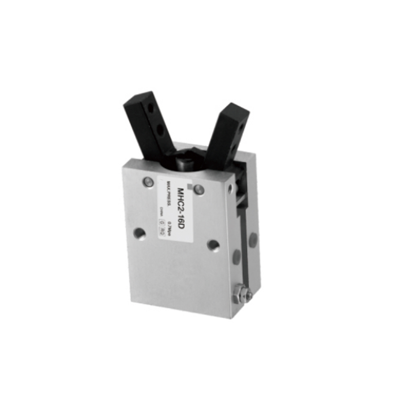
Demand for pneumatic gripper manufacturers spans a wider set of industries than most buyers initially expect, and the sizing and jaw configuration requirements differ meaningfully between them.
- Electronics assembly — small-bore parallel grippers in the 6mm to 20mm range for handling PCB modules, connectors, and small enclosures
- Automotive sub-assembly — mid-to-large bore three-jaw and toggle grippers for engine components, bearing races, and cylindrical metal parts
- Packaging and case handling — angular grippers with extended jaw fingers for cartons, pouches, and irregular soft-pack goods
- Machine tending — heavy duty parallel grippers rated for repeated exposure to coolant and metal chips inside CNC work cells
- Medical device assembly — precision small-bore grippers with tight repeatability tolerances, often under 0.02mm
Machine tending applications in particular tend to push manufacturers toward sealed, IP64-rated gripper housings, since coolant ingress into the piston bore is one of the fastest ways to shorten service life on a CNC-adjacent gripper installation.
Mounting the Gripper on a Robot Arm or Fixed Automation Frame
Most pneumatic grippers ship with a standardized mounting flange pattern that matches common robot wrist interfaces, but buyers integrating a gripper onto a fixed pick-and-place frame rather than a robot arm often need a simpler bracket mount instead. Confirming the mounting interface early avoids a common delay where the gripper arrives correctly built but the integrator has to machine an adapter plate before installation can proceed. Cable and air line routing also deserves early attention — grippers mounted on a moving robot wrist need flexible air hose rated for continuous flex cycling, which is a different specification than the rigid air line used on a fixed-position gripper.
Sensor Feedback Options
Position sensing on a pneumatic gripper is typically handled through magnetic reed switches or solid-state sensors mounted in a slot along the cylinder body, detecting when the piston reaches full open or full closed position. This binary open/closed feedback is sufficient for the majority of pick-and-place tasks, but applications needing to detect a part that is present but undersized, sometimes called a partial-close or part-detect function, require an intermediate sensor position or an analog pressure-based part-sensing circuit. Buyers with this requirement should confirm sensor slot compatibility and sensor type during the quotation stage rather than after the gripper has already been machined.
Maintenance Practices That Extend Gripper Lifespan Beyond the Warranty Period
- Inspect air line filtration monthly — particulate contamination in supply air is the leading cause of seal wear acceleration
- Re-lubricate the piston bore on a fixed interval rather than waiting for performance drop-off, typically every 500,000 to 1,000,000 cycles depending on duty cycle
- Check jaw guide backlash quarterly using a dial indicator; backlash exceeding 0.1mm signals guide rail wear requiring replacement
- Verify mounting bolt torque after the first month of operation, since vibration loosening is common on newly installed tooling
- Track cycle counts per gripper where possible, since most manufacturers rate service life in cycles rather than calendar time
Facilities that implement scheduled bore lubrication rather than reactive maintenance typically report gripper service life extending 30% to 40% beyond the manufacturer's baseline rating, based on maintenance logs shared by mid-size automation integrators handling multi-shift production lines.
Common Field Symptoms and What They Usually Mean
| Symptom | Likely Cause | Typical Fix |
|---|---|---|
| Grip force gradually weakening | Seal wear or bore scoring from contaminated air | Replace seal kit, check upstream filtration |
| Jaw play or wobble at full extension | Guide rail wear from high cycle count | Replace guide rail assembly |
| Slow or sluggish cycle time | Undersized air supply line or clogged flow control | Check line diameter and clean flow control orifice |
| Audible air leak from body | Piston seal failure or loose port fitting | Tighten fittings first, then inspect internal seals |
| Inconsistent part pickup | Worn or contaminated jaw finger surface | Clean or replace jaw finger inserts |
What to Verify Before Placing an Order With a Pneumatic Gripper Manufacturer
Sourcing from overseas manufacturers introduces a layer of due diligence that domestic buyers sometimes skip, and skipping it is where most sourcing regret originates. Before confirming an order, buyers should request the following directly from the manufacturer's sales engineering team:
Documentation to Request
- Actual measured force-versus-pressure curves, not just the theoretical formula-based figure
- Rated cycle life at the specific duty cycle matching your application, since a 5-million-cycle rating at low speed does not transfer directly to a high-speed line
- Sample dimensional inspection report for jaw parallelism and repeatability
- Standard lead time versus lead time for custom jaw finger machining, which is often the actual bottleneck in project timelines
Zhejiang CKT Pneumatic Co., Ltd is one of several established Chinese producers in this space that supply both standard catalog gripper lines and custom jaw finger machining for OEM integrators, and the same due diligence checklist above applies regardless of which pneumatic gripper manufacturer a buyer is evaluating. Requesting sample units for in-house cycle testing before committing to a full production order remains the single most reliable way to validate a new supplier relationship, particularly for buyers integrating grippers into a line where downtime cost is high.
What a Typical Quotation Timeline Looks Like
For standard catalog bore sizes with no custom jaw fingers, quotation turnaround from an established manufacturer is usually fast, often within one to two business days once the required force, stroke, and mounting interface are confirmed. Custom jaw finger machining extends that timeline meaningfully, since it requires a drawing review cycle before tooling can begin. Buyers with a hard project deadline should send part drawings for jaw finger design as early as possible, even before finalizing bore size, since jaw finger geometry and gripper sizing are often decided together rather than in strict sequence.
Building an Honest Total Cost of Ownership Picture
Unit price is only one line item in the real cost of deploying a pneumatic gripper across a production line. A complete total-cost comparison between two competing quotes should include the gripper unit price, expected seal kit replacement cost over a three-year window, air consumption cost at the facility's actual electricity and compressor efficiency rates, and the labor cost of scheduled maintenance versus reactive repair. A gripper priced 10% higher upfront but rated for double the cycle life on hardened guide rails frequently works out cheaper over a three-year deployment once replacement labor and line downtime are factored in, which is why unit price alone is a poor basis for comparing pneumatic gripper manufacturers.
A Quick Reference Glossary for Gripper Specification Sheets
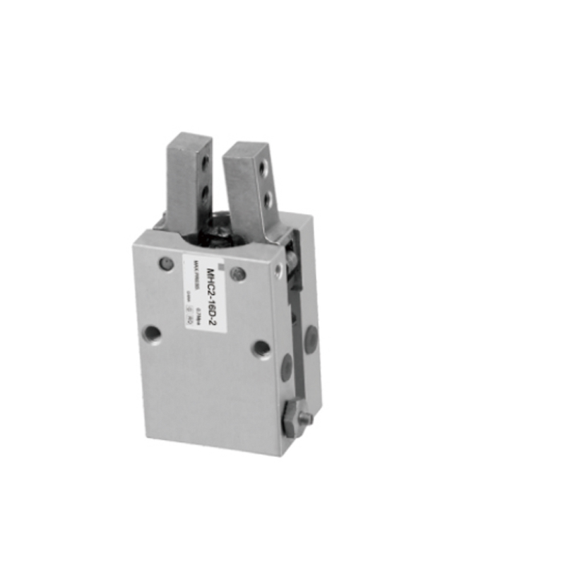
| Term | What It Means |
|---|---|
| Bore diameter | Internal diameter of the cylinder, the primary driver of theoretical force output |
| Stroke per jaw | Distance each jaw travels from fully open to fully closed |
| Repeatability | How consistently the jaws return to the same position cycle after cycle |
| Rated cycle life | Number of open-close cycles the gripper is expected to perform before major service is needed |
| Moment load capacity | Maximum off-center or torque load the jaw guides can tolerate without accelerated wear |
| IP rating | A standardized scale describing resistance to dust and liquid ingress into the gripper housing |
Frequently Asked Questions
What air pressure do most pneumatic grippers require to operate correctly?
Most industrial pneumatic grippers are rated for a working pressure range of 0.3 MPa to 0.7 MPa (roughly 44 to 100 psi), with 0.5 MPa to 0.6 MPa being the most common operating point on standard shop air systems. Running below the rated minimum reduces available grip force proportionally, while exceeding the rated maximum accelerates seal wear.
How long do pneumatic grippers typically last before needing replacement?
Standard catalog grippers are commonly rated between 3 million and 10 million cycles depending on bore size, jaw guide material, and duty cycle. Heavy-duty models with hardened steel guide rails and upgraded seals can extend well beyond that range with scheduled lubrication.
Can pneumatic grippers hold a part if air supply is lost mid-cycle?
Standard spring-assisted or double-acting parallel grippers will typically release or lose holding force if air pressure drops, which is why toggle-lever designs are specified for applications where holding force must be maintained even during a momentary air supply interruption.
What is the difference between single-acting and double-acting pneumatic grippers?
Single-acting grippers use air pressure to open or close in one direction and a spring to return the jaws, while double-acting grippers use air pressure for both opening and closing motions, generally producing higher and more consistent force in both directions at the cost of requiring two air lines instead of one.
How do I choose the correct bore size for a specific part weight?
Start from the required grip force (typically 4 to 6 times the part weight, higher for high-speed handling), then cross-reference that figure against the manufacturer's published force-versus-pressure chart for each bore size at your available supply pressure, rather than sizing by part dimensions alone.
Do pneumatic gripper manufacturers typically offer custom jaw finger machining?
Yes, most established manufacturers offer custom jaw finger machining to match specific part geometry, since standard flat jaw fingers are rarely optimal for irregular or delicate parts. Lead time for custom fingers is usually longer than for standard catalog units, so this should be confirmed early in the quotation process.
How much air does a typical pneumatic gripper consume per cycle?
Air consumption depends on bore size and stroke length, but as a rough reference a mid-size 20mm to 25mm bore parallel gripper typically consumes somewhere in the range of 0.05 to 0.15 liters of free air per full cycle at 0.5MPa supply pressure. Buyers running high-cycle-rate lines should request the manufacturer's measured consumption figures rather than estimating from bore size alone, since linkage design affects the actual swept volume.
Can a pneumatic gripper be used in a washdown or food-adjacent environment?
Yes, but it typically requires a gripper built with corrosion-resistant body materials, upgraded seal compounds rated for washdown chemicals, and sealed sensor slots to prevent moisture ingress. Standard catalog units are usually not rated for repeated washdown exposure without these upgrades, so this should be flagged explicitly when requesting a quotation.
What is the difference between jaw repeatability and jaw accuracy?
Repeatability describes how consistently the jaws return to the same position across repeated cycles, while accuracy describes how close that position is to the intended target position. A gripper can have excellent repeatability but still be slightly out of true position if it was not calibrated correctly during installation, which is why both figures matter for precision assembly work.
How do I know if I need a self-centering gripper instead of a standard parallel gripper?
Self-centering, typically three-jaw, grippers are the right choice whenever the part's center position matters for downstream placement accuracy and the part itself is round or symmetrical, since the jaws close simultaneously toward a common center regardless of where the part first lands within the jaw opening. A standard two-jaw parallel gripper does not guarantee this centering behavior unless the part is already positioned precisely before the jaws close.
What causes a pneumatic gripper to develop excessive jaw wobble over time?
Jaw wobble almost always traces back to wear in the guide rail or linear bearing that keeps the jaw traveling in a straight line. This wear accelerates faster on aluminum guide rails under high side-load conditions, which is why hardened steel guide rails are specified for high-cycle or heavy-part applications.