

 中文简体
中文简体
 English


Content
- 1 The Five Functional Groups of a Pneumatic System
- 2 Air Generation: Compressors and Receivers
- 3 Air Preparation: Filters, Regulators, and Lubricators
- 4 Pneumatic Control Components: How Airflow Is Directed and Timed
- 5 Actuators: Turning Air Pressure Into Motion
- 6 Distribution: Tubing, Piping, and Fittings
- 7 Sizing a Pneumatic System: Practical Guidelines
- 8 Where Pneumatic Components Are Used
- 9 Pneumatic vs. Hydraulic vs. Electric Actuation
- 10 Maintenance and Common Failure Points
- 11 Current Trends in Pneumatic Component Design
- 12 Frequently Asked Questions
- 12.1 What are the main pneumatic system components in a typical circuit?
- 12.2 What is the difference between a directional control valve and a flow control valve?
- 12.3 Why does a pneumatic cylinder move slower than expected?
- 12.4 How much air does a leak actually cost?
- 12.5 What is the role of a lubricator, and is it always required?
- 12.6 How do I choose between a single-acting and double-acting cylinder?
- 12.7 What causes moisture to appear in pneumatic lines?
- 12.8 Can pneumatic and electric actuation be combined in the same machine?
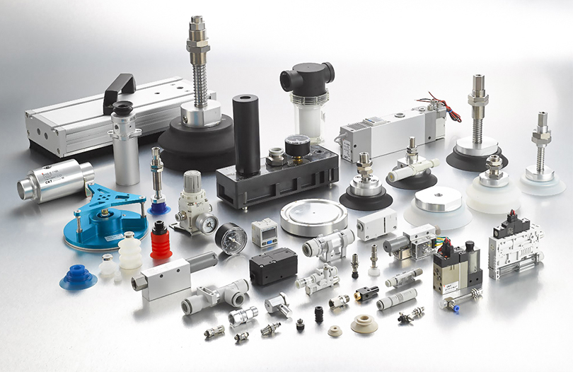
Pneumatic system components are the individual mechanical and control parts, compressors, air preparation units, valves, actuators, tubing, and fittings, that work together to generate, condition, direct, and apply compressed air as a source of mechanical power. Every functioning pneumatic circuit depends on five linked groups of hardware: air generation, air preparation, pneumatic control components, actuation, and connective plumbing. Understanding how these groups interact is the fastest way to diagnose a sluggish cylinder, cut air consumption, or specify a new system correctly the first time.
This guide breaks down each component group in practical terms, explains how pneumatic control components such as directional valves, flow regulators, and pressure controllers govern circuit behavior, and closes with a detailed FAQ for engineers, maintenance technicians, and procurement teams working with compressed air equipment.
The Five Functional Groups of a Pneumatic System
Rather than memorizing a long parts list, it helps to think of a pneumatic system as five stages that air passes through, from generation to useful work. Each stage has a distinct job, and a weak link in any one of them limits the performance of the whole system.
| Stage | Primary function | Typical components |
|---|---|---|
| Air generation | Convert electrical or mechanical energy into compressed air | Reciprocating, rotary screw, or scroll compressors; air receivers |
| Air preparation | Remove contaminants, moisture, and set working pressure | Filters, regulators, lubricators (FRL units), dryers |
| Pneumatic control | Direct, meter, and time the airflow | Directional control valves, flow controls, pressure switches |
| Actuation | Convert air pressure into linear or rotary motion | Cylinders, rotary actuators, air motors, grippers |
| Distribution | Carry air between components with minimal loss | Rigid piping, flexible tubing, push-in and threaded fittings |
A system is only as efficient as its weakest stage. Undersized tubing between the receiver and a fast-cycling cylinder, for example, can throttle flow just as severely as an undersized compressor, even though the compressor itself is never at fault.
Air Generation: Compressors and Receivers
The compressor is the starting point of every pneumatic circuit. Three compressor types dominate industrial use, each suited to a different duty cycle and flow demand.
Reciprocating (Piston) Compressors
Reciprocating compressors use a piston and cylinder arrangement to compress air in discrete strokes. They remain common in workshops and light manufacturing because of their lower upfront cost and simple maintenance, but they generate more heat and pulsation than rotary designs, which is why a receiver tank downstream is essential to smooth out delivery.
Rotary Screw Compressors
Rotary screw compressors use two interlocking helical rotors to compress air continuously rather than in pulses. This continuous-flow design makes rotary screw units the standard choice for production lines that run more than a few hours per shift, since they handle high duty cycles with less vibration and a smoother output pressure than piston compressors of comparable capacity.
Oil-Free Scroll Compressors
Scroll compressors compress air between two spiral-shaped elements, one fixed and one orbiting. Because they can run without lubricating oil in the compression chamber, they are favored in food processing, electronics assembly, and medical device manufacturing, where oil carryover into the air stream is unacceptable.
The Role of the Air Receiver
An air receiver tank stores compressed air downstream of the compressor and serves three practical purposes: it smooths out pressure pulsations, provides a buffer for sudden demand spikes, and allows condensed moisture to settle out before air moves further into the system. As a general sizing rule, many system designers target roughly one gallon of receiver volume per cubic foot per minute (CFM) of compressor output for stable, general-purpose applications, though high-demand or intermittent-load systems often require more.
Air Preparation: Filters, Regulators, and Lubricators
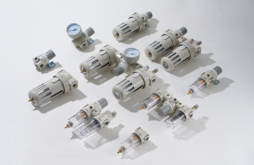
Raw compressed air straight from a compressor carries moisture, oil vapor, and particulate that will damage downstream valves and actuators if left untreated. The FRL unit, filter, regulator, lubricator, addresses this in three stages, usually mounted together as a compact assembly close to the point of use.
- Filters remove particulate matter, water droplets, and coalesced oil from the air stream, typically down to the 5-micron range for general use and finer for precision applications.
- Regulators reduce and stabilize line pressure to the level required by downstream equipment, protecting components rated for lower pressure than the main supply line.
- Lubricators introduce a fine oil mist into the air stream to reduce friction and wear in components such as cylinders and air tools that require ongoing lubrication; note that lubricated air is incompatible with oil-free FRL-rated equipment downstream.
Refrigerated and desiccant dryers are frequently added after the compressor and before the FRL unit in applications where moisture control is critical, such as painting, instrumentation air, or cold-environment operation where condensation could freeze inside valves.
Pneumatic Control Components: How Airflow Is Directed and Timed
Pneumatic control components are the devices that decide where compressed air goes, how fast it flows, and when it is switched on or off. They sit between the air preparation stage and the actuators, and they are typically the most engineering-intensive part of a circuit design.
Directional Control Valves
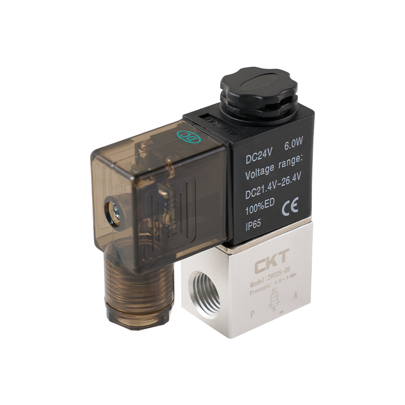
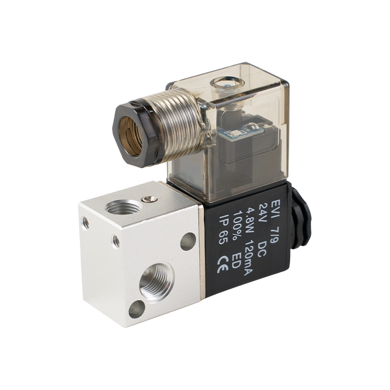
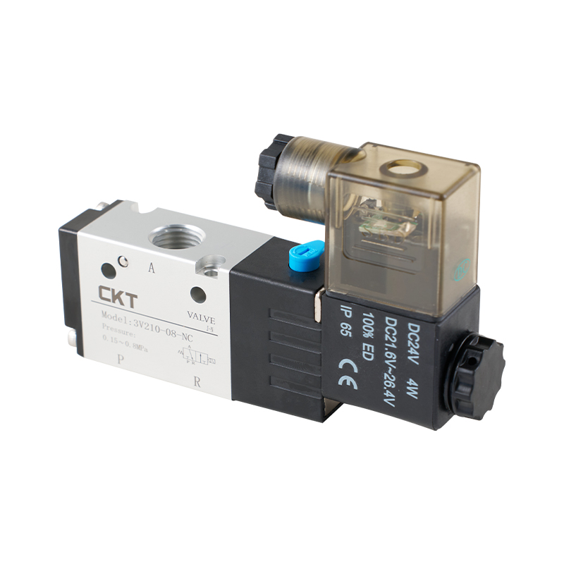
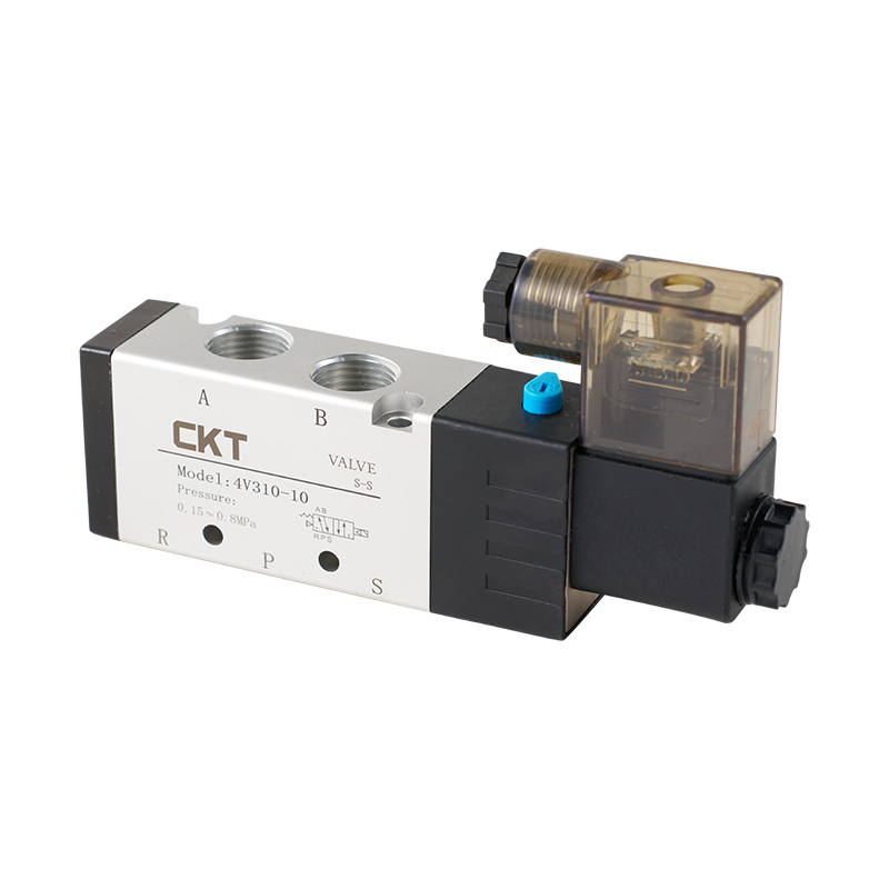
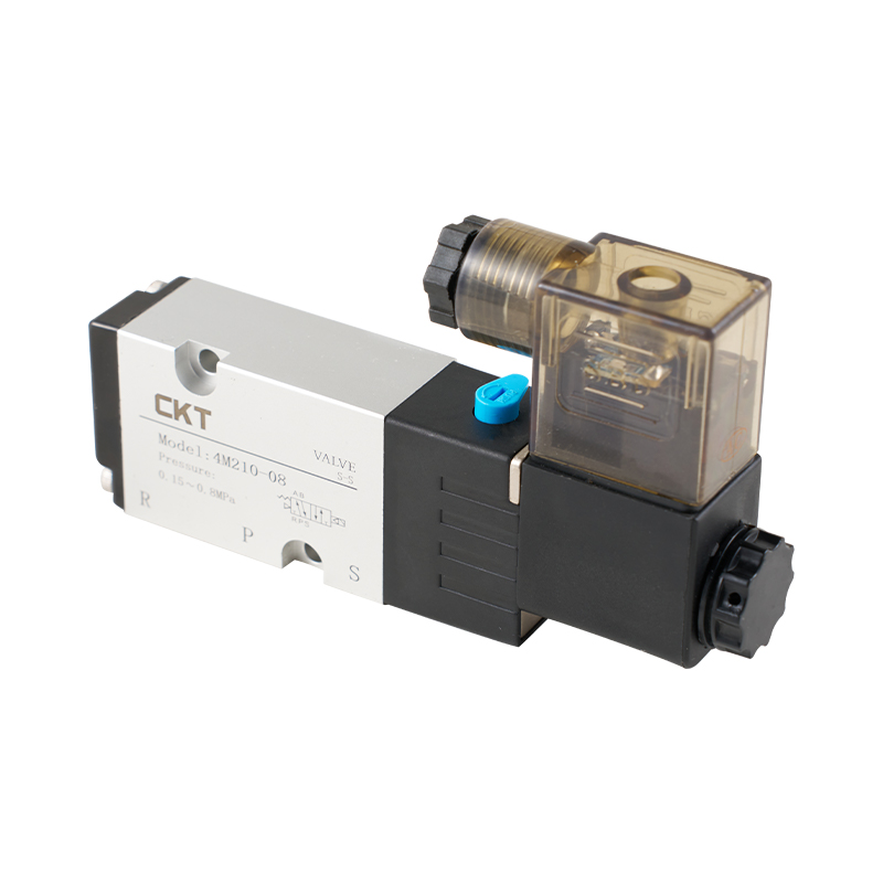
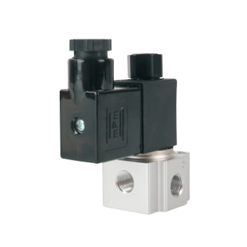
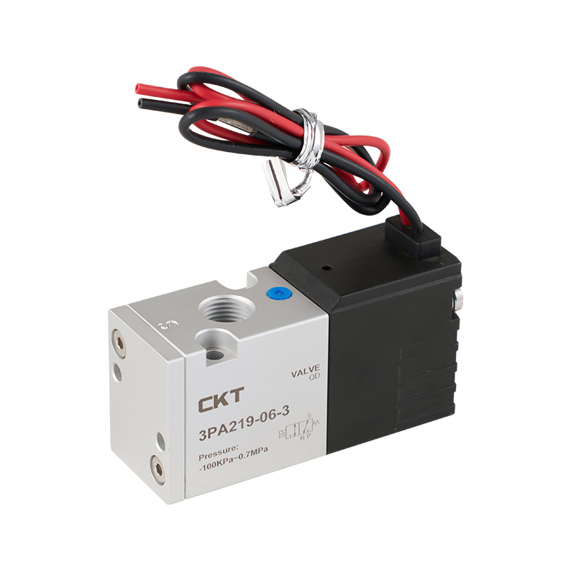
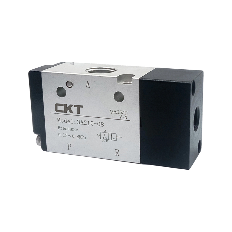
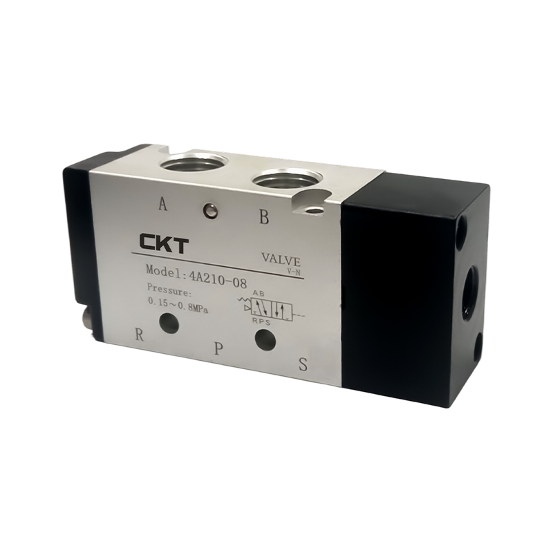
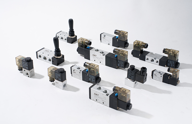
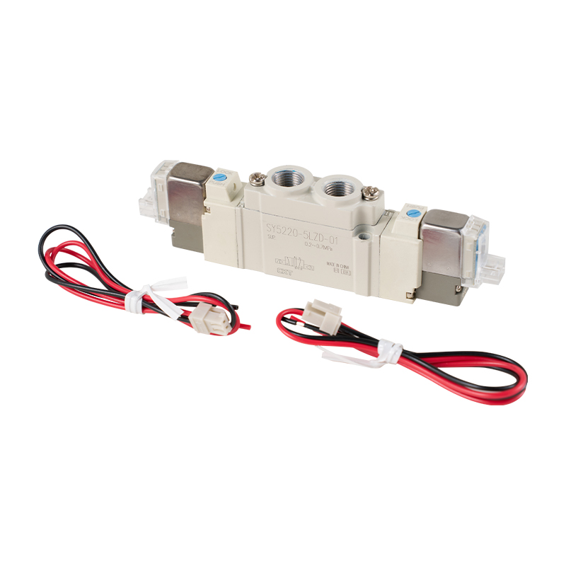
Directional control valves route air to one port or another, determining the direction of motion in a cylinder or actuator. They are classified by the number of ports and switching positions, commonly written as 3/2, 4/2, or 5/3, meaning the number of ports followed by the number of positions. A 5/2 valve, for example, has five ports and two switching positions and is the standard choice for controlling double-acting cylinders.
Flow Control Valves
Flow control valves meter the rate of airflow into or out of an actuator, which in turn controls actuation speed. Most industrial flow controls are one-way restrictors combined with a check valve, allowing free flow in one direction and restricted, adjustable flow in the other, a configuration known as meter-out control, generally preferred for cylinders because it resists load-induced overrun.
Pressure Control Components
Pressure switches, relief valves, and sequence valves protect the system and coordinate multi-actuator sequences. A pressure switch signals a control system when line pressure crosses a set threshold, while a relief valve vents air automatically if pressure exceeds a safe limit, protecting downstream seals and housings from overpressure damage.
Valve Actuation Methods
| Actuation type | How it works | Typical use case |
|---|---|---|
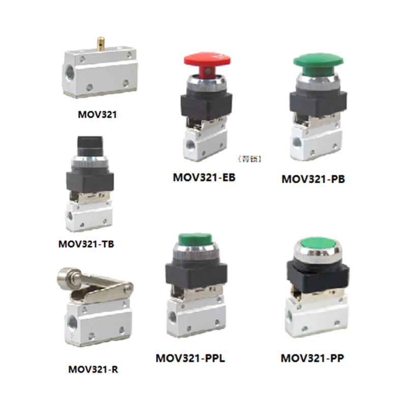
| Manual / hand lever | Operator physically shifts the valve spool | Manual override, testing, low-cycle applications |
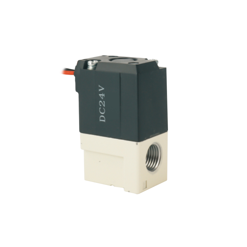
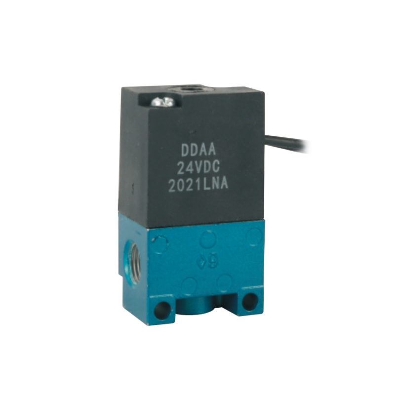
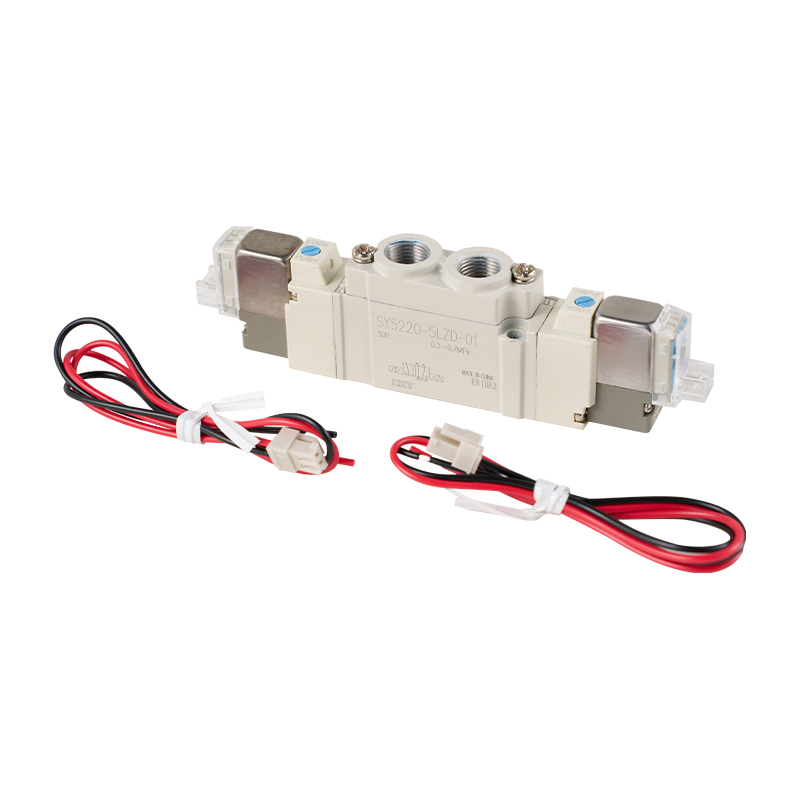
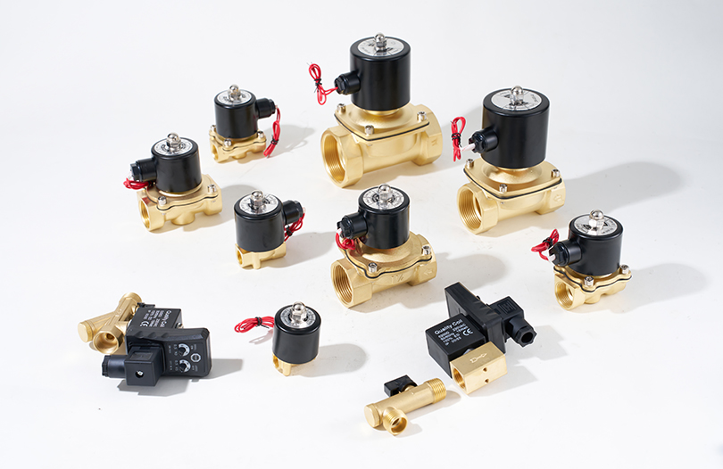
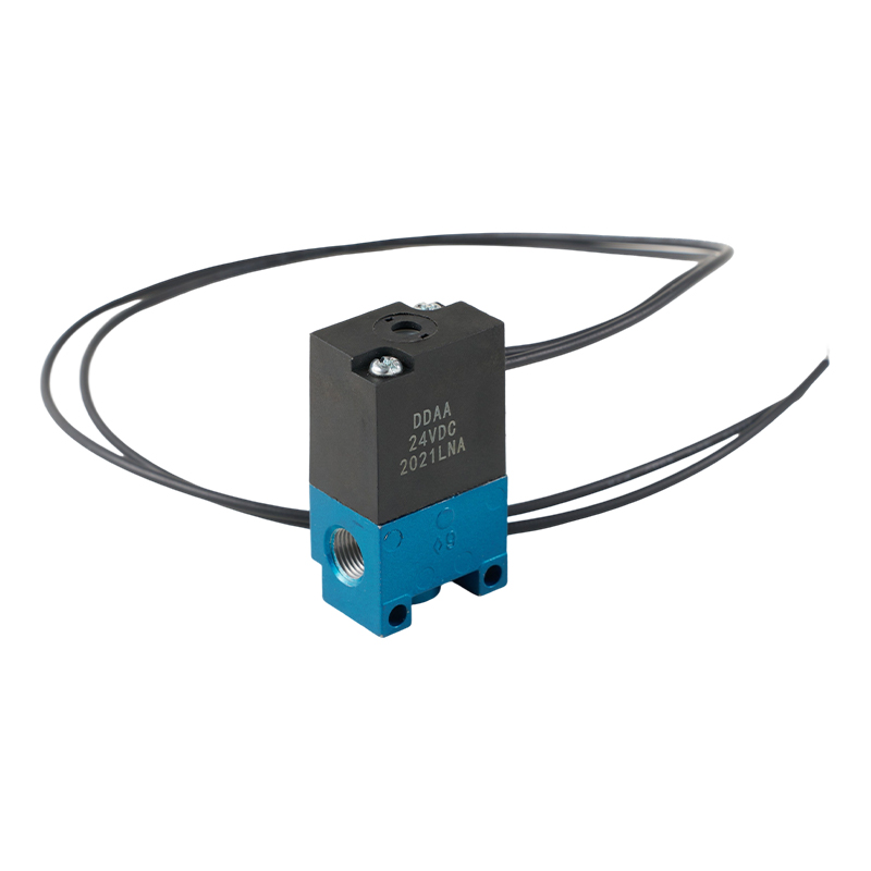
| Solenoid | Electromagnetic coil shifts the spool on electrical signal | PLC-controlled automated lines |
| Pilot air | A small air signal shifts the main valve spool | Systems without local electrical power, high-flow main valves |
| Mechanical / roller | Physical contact with a moving part trips the valve | Limit-switch style sequencing on machinery |
Solenoid-actuated valves dominate modern automated equipment because they integrate directly with programmable logic controllers, allowing precise, repeatable timing that would be difficult to achieve with manual or mechanical actuation alone.
Actuators: Turning Air Pressure Into Motion
Pneumatic Cylinders
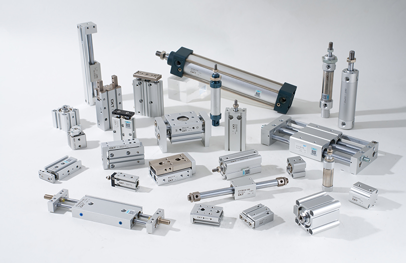
Cylinders are the most common pneumatic actuator, converting air pressure into linear force and motion. Single-acting cylinders use air pressure to move in one direction and a spring to return, while double-acting cylinders use air pressure for both the extend and retract strokes, delivering force in both directions and offering finer control over speed and positioning.
Rotary Actuators
Rotary actuators convert linear piston motion or vane movement into rotary output, typically through a rack-and-pinion or vane mechanism, and are common in applications such as valve turning, part flipping, and clamping arms that need a controlled rotational stroke, often 90 or 180 degrees.
Air Motors and Grippers
Air motors provide continuous rotary output for tools and mixers, valued for their ability to stall safely under load without overheating, unlike an electric motor. Pneumatic grippers, parallel or angular, use cylinder-driven jaws to pick and place parts in automated assembly, and are frequently specified by grip force and jaw stroke rather than by pressure rating alone.
Distribution: Tubing, Piping, and Fittings
Even a correctly specified compressor, FRL unit, and valve set will underperform if the distribution network is too small or leaks air. Line sizing, material choice, and fitting quality directly affect pressure drop and energy cost.
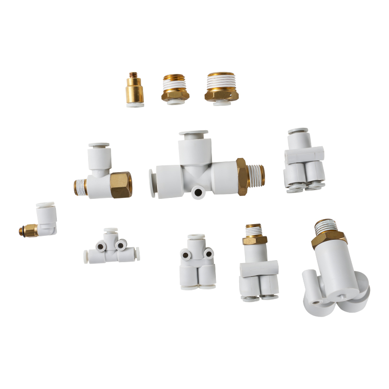
- Polyurethane and nylon tubing are the standard choice for flexible point-of-use runs because of their light weight, kink resistance, and compatibility with push-to-connect fittings.
- Aluminum or stainless piping is preferred for permanent main distribution headers, offering lower long-term leakage than threaded steel and easier reconfiguration than welded pipe.
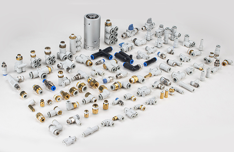
- Push-to-connect fittings allow rapid assembly and disassembly without tools, while threaded fittings offer a more permanent, vibration-resistant connection for fixed installations.
Undersized tubing is one of the most common and overlooked causes of poor cylinder performance. A cylinder that appears underpowered is frequently starved of flow by a tube diameter that is too small for its bore size and stroke speed, rather than by any fault in the cylinder itself.
Sizing a Pneumatic System: Practical Guidelines
Correct sizing prevents both wasted energy from an oversized compressor and chronic underperformance from an undersized one. The starting point is always total air demand, not just peak flow.
Calculating Cylinder Air Consumption
Air consumption for a double-acting cylinder is a function of bore area, stroke length, operating pressure, and cycle rate. As a working approximation, a cylinder consumes roughly its swept volume multiplied by the compression ratio at operating pressure, for every full cycle. Multiplying this per-cycle figure by cycles per minute gives the average flow demand that the compressor and distribution network must support continuously, not just momentarily.
Accounting for Leakage
Leakage is one of the largest hidden costs in a compressed air system. Industry surveys of industrial plants have repeatedly found that leakage commonly accounts for a significant share, often cited in the range of twenty to thirty percent, of total generated compressed air in systems that have not undergone a leak-detection program, making routine ultrasonic leak surveys one of the highest-return maintenance activities available for pneumatic equipment (source: U.S. Department of Energy compressed air system guidance).
Pressure Drop Budgeting
A well-designed system allocates an acceptable pressure drop budget across each stage, filtration, regulation, tubing runs, and valve banks, rather than allowing any single component to consume a disproportionate share. As a rule of thumb, keeping total pressure drop from the receiver to the point of use under roughly 10 percent of supply pressure preserves actuator force and cycle speed.
Where Pneumatic Components Are Used
Pneumatic systems remain the preferred power transmission method wherever cleanliness, simplicity, and tolerance for occasional stalling matter more than the raw power density of hydraulics.
| Industry | Typical components used | Why pneumatics is chosen |
|---|---|---|
| Automotive assembly | Solenoid valves, rotary actuators, grippers | Fast cycle times, repeatable clamping force |
| Food and beverage packaging | Oil-free compressors, stainless fittings | Contamination control, washdown durability |
| Material handling | Vacuum generators, pneumatic grippers | Lightweight tooling, gentle part handling |
| Woodworking and clamping | Single-acting cylinders, foot-pedal valves | Simple, low-cost linear clamping force |
| Process instrumentation | Regulators, precision pressure controllers | Stable, low-noise control signal air |
Pneumatic vs. Hydraulic vs. Electric Actuation
Choosing between pneumatic, hydraulic, and electric actuation depends on force requirements, precision, environment, and cost tolerance. None is universally better; each fits a different operating envelope.
| Factor | Pneumatic | Hydraulic | Electric |
|---|---|---|---|
| Force density | Moderate | Very high | High, with gearing |
| Speed | Fast | Moderate | Variable, programmable |
| Cleanliness | Clean, vents to atmosphere | Oil leakage risk | Clean |
| Precision positioning | Limited without added sensors | Good with servo valves | Excellent |
| Typical cost per axis | Low | High | Moderate to high |
Pneumatic systems remain the practical default for high-speed, moderate-force, repetitive motion, especially where overload safety matters, since a pneumatic actuator simply stalls under excess load rather than damaging the drivetrain.
Maintenance and Common Failure Points
Most pneumatic system failures trace back to a small set of recurring root causes, and routine attention to these points prevents the majority of unplanned downtime.
| Symptom | Likely cause | Recommended check |
|---|---|---|
| Cylinder cycles slowly | Undersized tubing, clogged filter, low regulator setpoint | Check line pressure at the cylinder port under load |
| Valve fails to shift | Worn seals, contaminated air, solenoid coil failure | Inspect coil resistance and spool for debris |
| Excess air consumption | Leaking fittings, worn cylinder seals | Ultrasonic leak survey during idle periods |
| Water in the air line | Undersized or missing dryer, receiver drain neglected | Verify automatic drain function and dryer dew point |
| Erratic actuator speed | Flow control valve drift, inconsistent supply pressure | Re-tune meter-out flow controls and check regulator stability |
A simple weekly walk-through, listening for hissing at fittings, checking receiver drain function, and confirming filter differential pressure, catches the large majority of developing faults before they cause a production stop.
Current Trends in Pneumatic Component Design
Pneumatic hardware is a mature technology, but component design continues to evolve in response to energy cost pressure and the wider push toward connected manufacturing equipment.
- Electronically monitored valve manifolds now report cycle counts, response time, and coil health back to a control system, allowing predictive rather than calendar-based maintenance.
- Low-friction cylinder seal materials reduce breakaway pressure, cutting air consumption at light loads without changing bore size.
- Digital proportional pressure regulators replace mechanical spring-loaded regulators in applications requiring programmable, repeatable pressure setpoints controlled directly from a PLC.
- Compact, high-flow push-to-connect fittings continue to shrink manifold footprints while maintaining flow coefficients close to those of larger threaded fittings.
The common thread across these developments is data visibility: pneumatic control components that once operated silently are increasingly instrumented so that flow, pressure, and cycle behavior can be tracked alongside the rest of a connected production line.
Frequently Asked Questions
What are the main pneumatic system components in a typical circuit?
A typical circuit includes a compressor for air generation, an FRL unit for air preparation, directional and flow control valves for pneumatic control, cylinders or rotary actuators for motion, and tubing or piping for distribution between them.
What is the difference between a directional control valve and a flow control valve?
A directional control valve determines which port air flows through, controlling the direction of actuator motion, while a flow control valve restricts the rate of that airflow, controlling the speed of motion. Most circuits use both together.
Why does a pneumatic cylinder move slower than expected?
Slow cylinder motion is most often caused by undersized tubing, a clogged filter element, a regulator set too low, or a flow control valve that has drifted closed over time, rather than by a fault in the cylinder itself.
How much air does a leak actually cost?
A single small leak may seem trivial, but because compressors run continuously to maintain line pressure, leaks add up. Ultrasonic leak surveys in industrial plants routinely uncover leakage rates that account for a meaningful share of total compressed air generation, making leak repair one of the fastest-payback maintenance activities in a facility.
What is the role of a lubricator, and is it always required?
A lubricator adds a fine oil mist to the air stream to reduce internal friction in components designed to run lubricated. It is not always required; many modern cylinders and valves use pre-lubricated, low-friction seals designed to run on dry, oil-free air, and mixing lubricated and non-lubricated components in the same circuit should be avoided.
How do I choose between a single-acting and double-acting cylinder?
Single-acting cylinders are suited to simple clamping or push tasks where a spring return is acceptable and only one direction requires force. Double-acting cylinders are the better choice when force and controlled speed are needed in both directions, which covers the majority of automated industrial applications.
What causes moisture to appear in pneumatic lines?
Compressing air raises its temperature and lowers its capacity to hold water vapor as it cools downstream, causing condensation. Without adequate drying and a properly functioning automatic drain on the receiver, this moisture travels through the system and can damage valves and cause corrosion.
Can pneumatic and electric actuation be combined in the same machine?
Yes, and this is common in modern automation. A typical hybrid design uses electric axes for precision positioning tasks and pneumatic cylinders for fast, repetitive clamping or ejection tasks, taking advantage of the strengths of each technology rather than relying on one exclusively.