


Content
- 1 Single Acting vs Double Acting Cylinder: The Short Answer
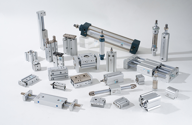
- 2 How a Single Acting Air Cylinder Works
- 3 How a Double Acting Air Cylinder Works
- 4 Side-by-Side Comparison: Single Acting vs Double Acting Cylinder
- 5 Force Output: Where the Numbers Really Diverge
- 6 Speed Control Differences Between the Two Types
- 7 Air Consumption: The Compressed Air Cost Comparison
- 8 Stroke Length Limitations: Why Single Acting Cylinders Top Out Early
- 9 Fail-Safe Behavior: A Critical Safety Consideration
- 10 Typical Application Areas for Each Cylinder Type
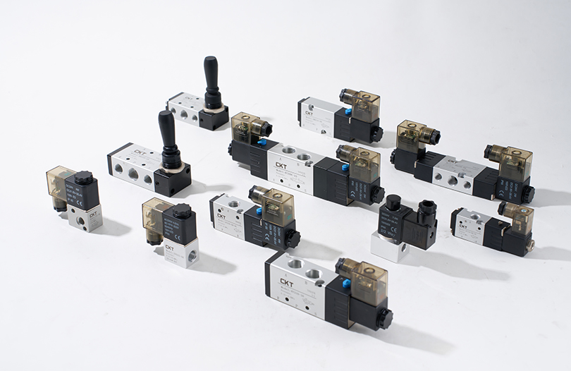
- 11 Control Valve Requirements: 3/2 vs 5/2
- 12 Maintenance Differences in Practice
- 13 Selecting the Right Bore Size for Either Type
- 14 Operating Pressure Ranges and Their Effect on Selection
- 15 Double Acting Cylinder Variants Worth Knowing
- 16 Summary: Choosing Between Single Acting and Double Acting
Single Acting vs Double Acting Cylinder: The Short Answer
If you need a quick verdict: a double acting cylinder gives you powered motion in both directions, while a single acting cylinder only uses compressed air for one stroke and relies on a spring or gravity for the return. That single difference shapes every aspect of how you select, install, and maintain an air cylinder in a real pneumatic system.
For applications where precise control, higher force output in both directions, and consistent speed during both extension and retraction matter — such as clamping fixtures, press tooling, and linear transfer systems — a double acting air cylinder is almost always the correct choice. For simpler jobs like spring-return clamping, valve actuation, or any task where one powered stroke is enough, a single acting cylinder reduces cost, complexity, and air consumption meaningfully.
The sections below break down how each type works at a mechanical level, where the real performance differences appear in practice, and how to make the right selection for your specific system.
How a Single Acting Air Cylinder Works
A single acting cylinder has one pressurized port. When compressed air enters, it pushes the piston in one direction — typically the extension stroke. The return stroke is powered by a compressed coil spring housed inside the cylinder body, or in some configurations by the weight of the load itself.
The spring is preloaded to a specific force value at the factory. Standard single acting cylinders use spring forces ranging from roughly 8 N to 60 N depending on bore size and stroke length. That spring force works against the air pressure during the power stroke, which means the effective output force at the rod end is lower than what the air pressure alone would produce.
For a 50 mm bore single acting cylinder operating at 6 bar (87 psi), the theoretical force is approximately 1,178 N. After subtracting a typical spring force of 25 N and accounting for seal friction (usually 5–10% of theoretical force), the actual rod force available for work drops to around 1,030–1,050 N. This deduction grows more significant at smaller bore sizes where spring force represents a larger percentage of the total available force.
Key Internal Components
- Single air port (usually at the cap end for push-type cylinders)
- Return spring seated between the piston face and the rod-end cap
- Breather port or vent on the spring side to prevent pressure buildup
- Single piston seal (one dynamic seal location)
- Rod seal at the cylinder head
The breather port is often overlooked during installation but it is critical. If it becomes blocked by contamination or is accidentally plugged, air trapped on the spring side creates back-pressure that reduces extension force and slows the stroke speed unpredictably.
How a Double Acting Air Cylinder Works
A double acting cylinder has two air ports — one at the cap end and one at the rod end. To extend the rod, compressed air enters the cap-end port while the rod-end port exhausts. To retract, the supply switches: air enters the rod end while the cap end exhausts. A directional control valve (typically a 5/2 or 4/2 solenoid valve) manages this switching.
Because there is no return spring absorbing force, the full pneumatic force is available in both directions. However, there is an important asymmetry to understand: the rod-end bore area is smaller than the cap-end bore area because the piston rod passes through it. This means the retraction force is always slightly lower than the extension force at the same supply pressure.
For a double acting cylinder with a 63 mm bore, a 20 mm rod diameter, operating at 6 bar:
- Extension force (cap end): π/4 × 63² × 6 = approximately 1,871 N
- Retraction force (rod end): π/4 × (63² – 20²) × 6 = approximately 1,682 N
That roughly 10–12% difference in force between extension and retraction is consistent across bore sizes and is a standard factor in double acting cylinder sizing calculations. If your retraction stroke carries a meaningful load, you must size the cylinder based on the retraction force, not the extension force.
Key Internal Components
- Two air ports (cap end and rod end)
- Double-lipped or U-cup piston seals on both sides of the piston
- Rod seal and wiper at the cylinder head
- No spring — full internal bore length available for stroke
- Optional internal cushions at both end positions
Side-by-Side Comparison: Single Acting vs Double Acting Cylinder
| Parameter | Single Acting Cylinder | Double Acting Cylinder |
|---|---|---|
| Air ports | 1 | 2 |
| Powered strokes | 1 (extension or retraction) | 2 (both directions) |
| Return mechanism | Spring or gravity | Compressed air |
| Speed control (retract) | Limited (spring-rate dependent) | Full (flow control valves) |
| Force on return stroke | Spring force only | Full pneumatic force (minus rod area) |
| Control valve required | 3/2 valve | 5/2 or 4/2 valve |
| Air consumption | Lower (one side pressurized) | Higher (both sides pressurized alternately) |
| Fail-safe behavior | Returns to home position (spring side) | Holds last position (without detent valve) |
| Maximum stroke (typical) | 25–200 mm (spring limits stroke) | Up to 2,000 mm or more |
| Relative unit cost | Lower | Slightly higher |
Force Output: Where the Numbers Really Diverge
Force calculation is where engineers most often make costly mistakes when comparing these two cylinder types. The formulas look similar on the surface, but the spring subtraction in a single acting cylinder introduces a variable that changes with stroke position.
A coil spring's force follows Hooke's Law: force increases linearly as it compresses. This means the effective output force of a single acting cylinder changes throughout the stroke. At the beginning of extension, the spring is near its free length and exerts minimal resistance. By full extension, it has compressed fully and exerts maximum resistance — subtracting the most force from the output at exactly the moment the rod meets the workpiece.
Consider a 40 mm bore single acting cylinder with a 100 mm stroke at 5 bar supply pressure:
- Theoretical pneumatic force: ~628 N
- Spring force at start of extension: ~10 N (near free length)
- Spring force at full extension: ~35 N (fully compressed)
- Effective force range: approximately 580–615 N across the stroke
For a double acting cylinder of the same 40 mm bore at 5 bar, the extension force is a consistent ~628 N throughout the stroke (minus seal friction, which is roughly constant). That consistency matters enormously in applications like pressing, forming, or clamping where the force at end-of-stroke is the critical design parameter.
The return stroke of a single acting cylinder is governed entirely by the spring. A spring designed to return the piston against seal friction plus a modest load might produce 15–50 N of net force depending on cylinder size. Compare this to the double acting cylinder's return force of several hundred newtons, and it becomes clear why single acting cylinders are unsuitable for applications where the retraction must overcome significant resistance or move a load quickly.
Speed Control Differences Between the Two Types
Speed control is achieved in pneumatic systems by restricting the exhaust airflow from the cylinder using flow control valves (meter-out configuration) or restricting the supply airflow (meter-in configuration). Meter-out control is generally preferred because it provides more stable, load-independent speed regulation.
For a double acting air cylinder, you install flow control valves at both ports. This gives you independent speed adjustment for extension and retraction — you can run the extension at 200 mm/s and the retraction at 500 mm/s, for example, with simple valve adjustments. This independent control is valuable in high-cycle automation where cycle time optimization is important.
For a single acting cylinder, you can meter the air in and out on the pressurized side to control extension speed. However, the return speed is fixed by the spring force and the load. If the spring is stiff and the load is light, the piston snaps back rapidly, creating impact loads on the end cap. If the spring is soft and the load is heavy, the return may be too slow or incomplete. You cannot simply turn a valve to slow the return of a spring-return cylinder — that requires changing the spring itself or adding a dedicated cushion.
In practice, this makes single acting cylinders poorly suited to applications with variable loads on the return stroke or where return speed needs to be tuned to match a process. Packaging lines, robotic end-of-arm tooling, and transfer conveyors typically require that both stroke speeds be independently dialed in — and that pushes most of those applications firmly into double acting territory.
Air Consumption: The Compressed Air Cost Comparison
Compressed air is one of the most expensive utilities in a manufacturing plant. Studies by organizations like the U.S. Department of Energy have estimated that compressed air systems account for 20–30% of industrial electricity consumption, and pneumatic actuators are the primary consumers within those systems. Understanding the air consumption difference between single and double acting cylinders is therefore not an academic exercise — it has direct impact on operating costs.
A single acting cylinder consumes pressurized air only on the power stroke. The return stroke is driven by the spring, and the air from the power stroke side simply exhausts to atmosphere. For one complete cycle, the air volume consumed equals the bore area multiplied by the stroke length, adjusted for compression ratio at supply pressure.
A double acting cylinder consumes air on both strokes. However, because the rod-end bore area is smaller than the cap-end, the volume consumed on the retraction stroke is slightly less than on the extension stroke. The total air consumed per cycle is roughly 1.7 to 1.9 times the air consumed by an equivalent single acting cylinder, depending on rod diameter.
For a concrete example: a 50 mm bore, 100 mm stroke double acting cylinder operating at 6 bar and cycling at 60 times per minute consumes approximately:
- Cap end per stroke: (π/4 × 0.05²) × 0.1 × (6+1) = ~1.37 liters (free air) per stroke
- Rod end per stroke (assuming 20 mm rod): approximately 1.09 liters per stroke
- Total per minute at 60 cycles: ~146 liters/min free air
An equivalent single acting cylinder would consume approximately 82 liters/min. Across a machine with 20 such cylinders running two shifts, the annual electricity cost difference becomes measurable. When you are deploying large numbers of cylinders, or when cylinders operate in long strokes or at high cycle rates, the air consumption difference meaningfully impacts operating economics — even if the double acting cylinder is otherwise technically superior.
Stroke Length Limitations: Why Single Acting Cylinders Top Out Early
The internal return spring in a single acting cylinder physically limits how long the stroke can be. As stroke length increases, you need a longer spring, which requires a longer cylinder body — and longer springs are harder to keep stable and properly guided inside the bore. They also add more length to the overall cylinder even in the retracted position.
Most manufacturers offer single acting cylinders with maximum strokes of 25 mm to 200 mm. A few specialty designs reach 300 mm. Beyond that, the spring becomes impractical. If your application needs a 400 mm, 600 mm, or 1,000 mm stroke, a double acting cylinder is the only viable option in the standard air cylinder product range.
This limitation also interacts with force: as stroke increases, so does spring compression at full extension, which means more force is consumed overcoming the spring at end-of-stroke. For strokes longer than about 100–150 mm in a single acting design, the spring force subtraction starts to become a significant percentage of the total available pneumatic force, particularly in small bore sizes.
Fail-Safe Behavior: A Critical Safety Consideration
One of the most practically important differences between these two cylinder types is what happens when air supply is lost — whether from a compressor failure, an emergency stop, or a line rupture.
A single acting spring-return cylinder will automatically return to its spring-side position when pressure drops. If the cylinder is configured to clamp a workpiece on the power stroke (extension), loss of air causes it to release. If it is configured with spring-extend (which some designs offer for safety clamping), loss of air causes it to clamp. This deterministic behavior is deliberately engineered for safety applications.
Machine guarding, brake release mechanisms, and emergency stops frequently use single acting cylinders precisely because their fail-safe behavior is predictable and guaranteed by the spring, not by an electrical signal or a valve position.
A double acting cylinder, by contrast, holds its last position when air is lost — if the directional valve is a detent or spring-center type that blocks both ports. This is sometimes desirable (you don't want a loaded axis to drop), but it can also be hazardous if the cylinder was in the middle of a clamping or pressing operation when the air failed.
Safety standards including ISO 13849 and IEC 62061 require machine designers to analyze and document the behavior of all actuators under fault conditions. Choosing between a single acting and double acting cylinder is directly relevant to this analysis, and the fail-safe characteristic of the single acting type often earns it a place in safety-rated circuits even when a double acting cylinder might otherwise be used for its greater controllability.
Typical Application Areas for Each Cylinder Type
Where Single Acting Cylinders Excel
- Pneumatic valve actuators: Quarter-turn ball valves and gate valves often use spring-return single acting cylinders so the valve fails to a known safe position (open or closed) when air pressure drops.
- Clamping fixtures with short strokes: Holding workpieces for machining where the machining force is always in one direction and the clamp only needs to release (retract) under low load.
- Door and hatch control: Where spring return ensures closure on power failure.
- Sorting and diverting gates: Simple flip gates on conveyors where one direction is always the default and the other is the powered actuation.
- Brake and clutch engagement: Spring-apply brakes for emergency stops — the brake engages when air is lost.
Where Double Acting Cylinders Are Required
- Pick-and-place automation: Both extension and retraction must be powered, speed-controlled, and able to handle variable part weights.
- Press and forming operations: High force in both directions; the return must overcome workpiece springback or ejector resistance.
- Long-stroke linear transfer: Any stroke beyond 200 mm requires a double acting air cylinder.
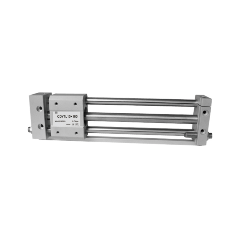
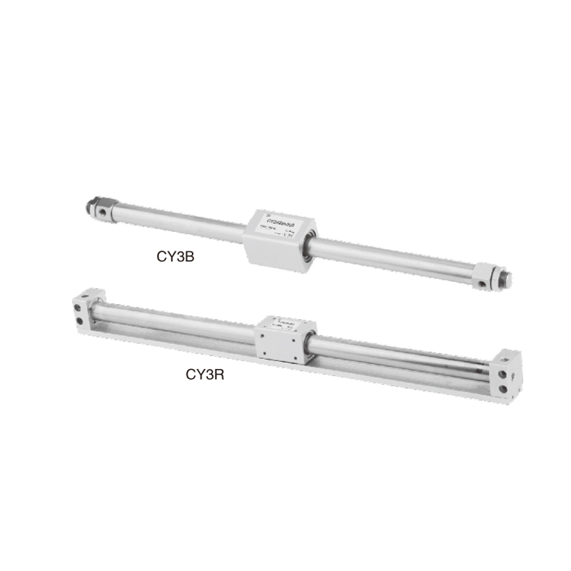
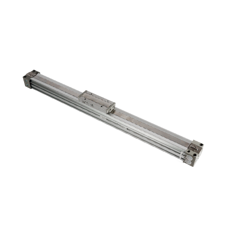
- Rodless cylinder applications: Rodless pneumatic cylinders are inherently double acting, used for long-travel horizontal transfer where a conventional rod cylinder would be impractically long.
- Tilting and rotating tables: Both tipping and returning the table require powered, controllable force.
- High-cycle applications above 60 cycles/min: Where retraction speed must be tuned precisely to maintain cycle time without shock loading.
Control Valve Requirements: 3/2 vs 5/2
The difference in air ports between single and double acting cylinders directly determines the control valve required, which affects wiring, manifold design, and cost.
A 3/2 valve (3 ports, 2 positions) is sufficient for a single acting cylinder. In one position, it connects the supply to the cylinder port. In the other position, it connects the cylinder port to exhaust. The spring handles the rest. A 3/2 valve is physically smaller and typically 20–40% less expensive than a 5/2 valve. It also requires a simpler manifold block when many valves are ganged together.
A 5/2 valve (5 ports, 2 positions) is the standard for a double acting cylinder. In one position, supply goes to the cap end and the rod end exhausts. In the other position, supply goes to the rod end and the cap end exhausts. The two exhaust ports are typically where flow control valves are installed for speed regulation.
In systems with many axes — a 20-station assembly machine, for example — the cumulative cost difference between 20 3/2 valves and 20 5/2 valves can be meaningful. For smaller cylinders in simple applications, this cost difference often justifies specifying a single acting cylinder even when a double acting one might offer marginally better performance.
Note also that 5/2 valves are available with spring return, detent (memory), or dual solenoid actuation, each offering different fail-state behavior. The choice of valve type interacts with the cylinder type to determine system-level safety behavior — something that must be analyzed at the design stage, not retrofitted later.
Maintenance Differences in Practice
In terms of seal count, a single acting cylinder has fewer dynamic sealing surfaces than a double acting one. Fewer seals generally means fewer leak paths and slightly lower seal replacement frequency. However, the spring in a single acting cylinder is an additional wear component that does not exist in a double acting design.
Springs in pneumatic cylinders are rated for millions of cycles, but they do fatigue. A spring that has lost tension will cause the cylinder to return slowly, incompletely, or not at all. In a machine that runs 24 hours a day at 60 cycles per minute, a cylinder completes over 86 million cycles per year. Spring fatigue at that cycle rate is a real maintenance consideration, particularly in cylinders with shorter strokes where spring compression per cycle is a larger fraction of the spring's total travel.
For double acting cylinders, seal wear is the primary maintenance concern. Modern polyurethane and PTFE-based piston seals typically last 50 to 100 million cycles under normal operating conditions with clean, lubricated or oil-free dry air. Contaminated air supply is the most common cause of premature seal failure in both cylinder types.
The breather port on a single acting cylinder deserves specific mention: it should be inspected and cleaned regularly as part of preventive maintenance. A clogged breather reduces performance gradually enough that it may not be noticed until the cylinder begins misbehaving — making scheduled inspection more important than reactive repair.
Selecting the Right Bore Size for Either Type
Correct bore sizing is the most fundamental step in specifying any air cylinder. Under-sizing a bore produces insufficient force; over-sizing wastes air and money. The process is slightly different for each cylinder type.
For Single Acting Cylinders
- Determine the required force at end-of-stroke (where spring compression is maximum).
- Add the maximum spring force for the selected stroke to the required output force.
- Add seal friction (typically 10% of theoretical force as a safety margin).
- Calculate the bore area needed: Area = Total Force ÷ Supply Pressure.
- Select the next standard bore size up from the calculated area.
- Verify that the spring force is sufficient to return the piston against the load on the return stroke.
For Double Acting Cylinders
- Determine the required force for both the extension and retraction strokes separately.
- Calculate the bore required for each stroke at the available supply pressure, accounting for rod-end area reduction on the retraction calculation.
- Add a safety factor of 1.25–1.5× to account for friction, misalignment, and pressure variations.
- Select the bore that satisfies both stroke requirements — typically the larger of the two calculated values.
- Check the rod diameter against buckling limits if the rod is in compression and is long relative to its diameter.
Standard bore sizes across both cylinder types follow ISO 15552 conventions: 12, 16, 20, 25, 32, 40, 50, 63, 80, 100, 125, 160, and 200 mm are the most common. Specifying to a standard bore size ensures interchangeability between manufacturers and simplifies spare parts management.
Operating Pressure Ranges and Their Effect on Selection
Both single and double acting air cylinders are rated for typical operating pressures of 1 to 10 bar (14.5 to 145 psi), with the most common industrial supply pressure being 6 bar (87 psi). However, operating at lower pressures affects each type differently.
For single acting cylinders, a minimum operating pressure is required to overcome the spring preload plus seal friction. If the supply pressure drops to, say, 3 bar in a system rated for 6 bar, the effective output force drops by roughly 50%. But the spring force remains unchanged — meaning the single acting cylinder's force reduction is disproportionate compared to the double acting type at the same reduced pressure.
Additionally, single acting cylinders may have a minimum operating pressure specified by the manufacturer below which the cylinder will not fully extend against the spring. This threshold is typically listed in the product datasheet and should be compared against the minimum guaranteed supply pressure in your system — not the nominal supply pressure.
Double acting cylinders are less sensitive to pressure fluctuations in this regard because neither stroke has a fixed mechanical resistance to overcome beyond friction. At lower pressures, the force output decreases proportionally on both strokes, and the system still functions — just with less force available.
Double Acting Cylinder Variants Worth Knowing
Within the double acting category, several specialized designs address specific application requirements:
- Double rod double acting cylinder: The piston rod extends from both ends of the cylinder. Both sides have the same bore area, so extension and retraction forces are identical. Used when symmetrical force output is critical or when the through-rod is needed for mechanical connection or measurement reference on both sides.
- Tandem cylinder: Two double acting cylinders mounted in series on the same piston rod. The two pistons act simultaneously, roughly doubling the available force from a given bore diameter. Used when bore space is limited but high force is needed.
- Rodless double acting cylinder: The load connects externally to the piston via a slot or magnetic coupling in the cylinder wall. Enables very long strokes in a compact package. Available in strokes to 6,000 mm or more.
- Guided double acting cylinder: Integrates linear guides directly with the cylinder body to eliminate rotational torque and side-load forces on the rod. Critical for applications where precise linear motion and angular accuracy are required without external guides.
Summary: Choosing Between Single Acting and Double Acting
The decision is straightforward once you have mapped your application requirements against the key differentiators. Use the following framework:
- Choose single acting when: the application needs fail-safe return to a home position; the stroke is short (under 150–200 mm); the return force required is minimal; air consumption must be minimized; simpler valve circuitry is preferred; and cost savings on valves and plumbing are meaningful at scale.
- Choose double acting when: both strokes must deliver meaningful force; stroke length exceeds 200 mm; independent speed control of both strokes is required; cycle rate is high and return speed must be tuned; the load on the return stroke is variable or significant; or the application is a press, transfer, or pick-and-place mechanism.
In the vast majority of industrial automation applications, the double acting air cylinder is the default workhorse — flexible, powerful, and fully controllable. The single acting cylinder earns its place in simpler, safety-critical, or cost-sensitive designs where its inherent spring-return behavior is a feature rather than a limitation. Understanding both types at this level of detail allows you to make that selection deliberately, based on engineering requirements rather than convention.


