

 中文简体
中文简体
 English


Content
- 1 What Pneumatic Cylinder Design Really Decides
- 2 Start With the Load: Bore Size and Force Calculation
- 3 Choosing the Construction Family That Fits the Job
- 4 Stroke Length, Speed and Cycle Time
- 5 Mounting Styles and the Cost of Misalignment
- 6 Compact Cylinder Design for Tight Spaces
- 7 Rodless Cylinder Design for Long Strokes
- 8 Cushioning: Designing Out End-of-Stroke Shock
- 9 Seals, Temperature and Air Quality
- 10 Standards That Shape Pneumatic Cylinder Design
- 11 A Pre-Order Checklist for Pneumatic Cylinder Design
- 12 Frequently Asked Questions About Pneumatic Cylinder Design
- 12.1 How do I calculate the force a pneumatic cylinder can produce?
- 12.2 What bore size do I need for a 500 kg load?
- 12.3 Which cylinder design is best for long strokes?
- 12.4 Why does my cylinder fail from side loading even though the force is correct?
- 12.5 Can a standard pneumatic cylinder hold a load in mid-stroke?
- 12.6 What is the difference between single-acting and double-acting cylinder designs?
What Pneumatic Cylinder Design Really Decides
A machine builder ordering a pneumatic cylinder usually starts with one number: the mass of the load the cylinder must move. But the cylinder design itself — the bore, the construction family, the mounting, the cushioning and the sealing system — decides whether that load moves reliably for ten million cycles or fails inside the first year. Good pneumatic cylinder design is not a single formula; it is a chain of decisions that all have to remain consistent with the application.
The direct answer: pneumatic cylinder design is the systematic matching of bore diameter, stroke length, construction type, mounting, cushioning and seal material to the load, the available air pressure, the required cycle time and the working environment. Once these six values match the application, everything else — force charts, accessory lists, sensor placement — becomes detail work.
This is the same design logic that CKT Pneumatic applies to every cylinder series we manufacture and test in-house. The guidance below is written from that engineering point of view, with the numbers and trade-offs that matter on a real drawing board.
Start With the Load: Bore Size and Force Calculation
Every cylinder design starts with the force requirement. A double-acting cylinder generates force by applying compressed air to the piston area, so the theoretical force is simple: F = P × A, where P is the gauge pressure in pascals and A is the effective piston area in square metres. For the extend stroke, A = (π/4) × D².
A worked example to anchor the numbers
Consider a 63 mm bore cylinder supplied at 0.6 MPa. The piston area is (π/4) × (0.063 m)² = 0.00312 m². Multiplying by 600,000 Pa gives 1,870 N of theoretical extend force. Because seals, rod packing and circuit pressure losses absorb energy, the practical force is normally 75–90% of the theoretical value, so the designer can rely on roughly 1,400–1,680 N for ongoing operation. The same order of magnitude appears in the force charts in Power & Motion’s “Pneumatic Cylinder Design Factors” guidance and the selection data used across the industry.
Retract force is never the same as extend force
On the return stroke the rod occupies part of the bore, so the effective area is smaller. A 63 mm bore with a 20 mm rod has a retract area of (π/4) × (0.063² − 0.020²) = 0.00281 m², which at 0.6 MPa produces only 1,685 N. If the return stroke carries the heavier load, size the bore from the retract case using the rod-adjusted area — a common mistake that shows up as slow return speed and premature rod seal wear.
| Bore diameter (mm) | Piston area (cm²) | Force at 0.4 MPa (N) | Force at 0.6 MPa (N) | Force at 0.7 MPa (N) |
|---|---|---|---|---|
| 32 | 8.04 | 322 | 483 | 563 |
| 40 | 12.57 | 503 | 754 | 880 |
| 50 | 19.63 | 785 | 1178 | 1374 |
| 63 | 31.17 | 1247 | 1870 | 2182 |
| 80 | 50.27 | 2011 | 3016 | 3519 |
| 100 | 78.54 | 3142 | 4712 | 5498 |
After calculating the ideal bore, add a design margin. A safety factor of 1.25–1.5 over the theoretical force is standard for dynamic applications; the margin absorbs pressure fluctuations, seal wear and the speed effects that appear in real machines.
Choosing the Construction Family That Fits the Job
The construction of a cylinder — how the tube, end caps and rod are held together — defines the bore range it can cover, how easy it is to repair, and how much side load it can tolerate. For a practical view of the internal parts, a closer look at the anatomy of pneumatic cylinders explains the role of the tube, cap, head, piston and seals. The three families that dominate industrial design each have a distinct logic.
Tie-rod cylinders: the industrial default
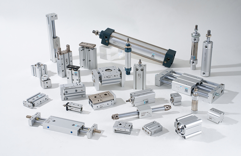
Tie-rod cylinders clamp the end caps with long bolts running the full length of the body. They cover the widest bore range, typically 32–320 mm, can be disassembled for seal replacement, and tolerate the highest thrust loads. SC series tie-rod cylinders follow this construction, and it remains the most specified family in our catalogue because it is easy to mount, easy to repair and simple to match with ISO accessories.
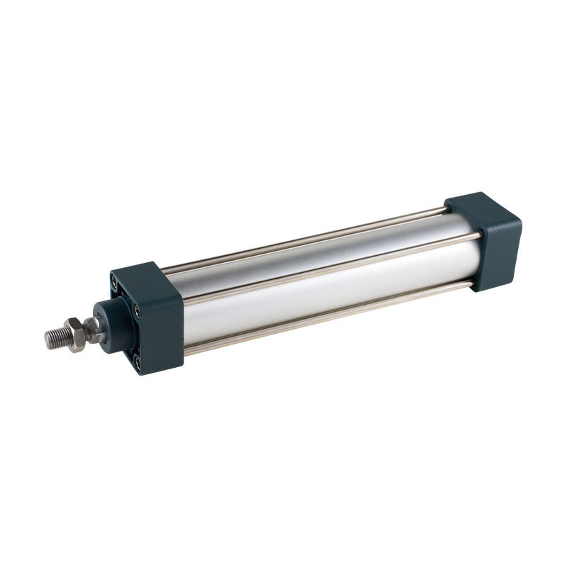 SC Series (Tie Rod Type) Standard Cylinder Suppliers, OEM/ODM Factory - ZhejiangCKT Pneumatic is a China wholesale SC Series (Tie Rod Type) Standard Cylinder suppliers and OEM/ODM factory, 1. The piston seal adopts a ...View Product →
Round-body cylinders: compact and cost-conscious
Round-body cylinders, typically 8–25 mm bore, use a drawn or rolled tube with threaded end caps. They are lightweight, inexpensive and ideal for short-stroke movements in small machines. The trade-off is a lower side-load capacity and little or no adjustable cushioning, so they should be reserved for clean, axial motion tasks.
Profile cylinders: built for modern sensor-heavy machines
Profile cylinders use an extruded aluminium body with integrated air ports and sensor slots. Their main design advantage is integration: magnetic switches clip into the slots, valves can be banked directly on the body, and the flat surfaces make machine mounting far cleaner than with round tubes. They are the default in modern assembly and packaging lines where sensors, manifolds and guarding all attach to the actuator itself.
Stroke Length, Speed and Cycle Time
Set the stroke with margins, not with the exact travel
Nominal stroke should equal the required travel plus a margin at both ends, normally 5–10 mm per end. In vertical applications, add the full compression of the cushion or bumper as well. If the piston bottoms out on the end cap at the end of every stroke, the cylinder will wear out far faster than any catalogue lifetime suggests. A stroke that is 10 mm too short can turn a 10-million-cycle design into a 200,000-cycle repair item.
Speed depends on the whole circuit, not the cylinder alone
Cylinder speed is set jointly by the bore, the valve flow coefficient, the port size and the supply line. A well-balanced circuit runs a standard cylinder at roughly 0.1–0.6 m/s. As noted in Fluid Power World’s designer’s guide, a U-cup sealed piston can be expected to run at speeds above 20 in./sec — about 0.5 m/s — without excessive friction or lubrication problems. If the target is 1 m/s or higher, the valve must be upsized and the porting redesigned together with the cylinder; the cylinder alone cannot create speed.
Cycle time is estimated with a simple procedure:
- Define the travel and add the stroke margin.
- Set the average speed for the extend and retract directions.
- Calculate time per direction as stroke divided by speed.
- Add dwell time and valve response time to get the full cycle time.
As a concrete example, a 300 mm stroke at 0.5 m/s takes 0.6 s in each direction; with 0.2 s of dwell, the full extend–retract cycle is about 1.4 s, which corresponds to roughly 43 cycles/min. If the machine requires 60 cycles/min, either the speed must rise to about 0.6 m/s each way or the stroke must shrink — and both changes affect valve sizing, cushioning and mounting stiffness.
Mounting Styles and the Cost of Misalignment
Four mounting families, four alignment behaviours
- Foot mounts are the simplest and cheapest, but the body can flex under load, so alignment depends entirely on the machine frame.
- Flange mounts (head or rear) are rigid and suited to high-thrust applications where the cylinder body must not move.
- Clevis mounts allow the cylinder to swing in one plane, which is essential when the rod travels along an arc through a linkage.
- Trunnion mounts (centre or rear) support the body on both sides and are the best choice for heavy cylinders that need a controlled pivot.
Side loads are the most common reason a cylinder design fails
When the line of thrust is not along the rod centreline, the rod and front bearing must absorb a bending moment. Even a lateral force equal to only a few percent of the rated thrust will measurably shorten bearing and seal life. This is why both Machine Design’s selection guidelines and Power & Motion’s cylinder design factors insist on keeping the cylinder thrust as close as possible to the centreline of the piston rod.
When geometry forces an offset, the correct answer is a guided design — a multi-axis cylinder, a slide cylinder, or a compact cylinder with a guide rod — rather than simply choosing a larger standard cylinder. A bigger bore creates more force but does nothing to fix a bending moment.
Compact Cylinder Design for Tight Spaces
When the machine envelope is fixed, compact cylinders are the standard answer. They follow the same force logic as full-size cylinders but package the piston and rod inside a short body, usually built to ISO 21287. The main design compromise is stroke: a very short body cannot guide a long rod without extra bearing support, so most compact designs work best on strokes below roughly 100–150 mm.
Where compact cylinders earn their space
Clamping, indexing, feeding and part ejection are all short-stroke, high-cycle jobs. Replacing a tie-rod cylinder with a compact body can save 30–50 mm per axis; on a machine with six or eight axes, that saving changes the whole frame and guarding layout. The compact body also reduces moving mass, which lowers the kinetic energy at end-of-stroke and allows faster cycling with the same valve.
Keep the guide function separate from the force function
Because the compact body offers limited rod support, never expect a compact cylinder to absorb bending moments. For pure axial motion, a plain compact body is perfectly adequate — CQ2 series compact thin cylinders handle clamping and pushing duties well. Whenever the design generates an off-axis or moment load, move to a guided variant such as CQM with a guide rod, or to a slide cylinder family that carries its own linear guide.
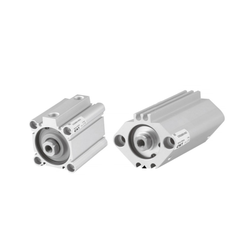 CQ2 Series Thin Cylinder Suppliers, OEM/ODM Factory - Zhejiang CKT Pneumatic Co.CKT Pneumatic is a China wholesale CQ2 Series Thin Cylinder suppliers and OEM/ODM factory, 1. The magnetic switch does not protrude: prev...View Product →
Rodless Cylinder Design for Long Strokes
Rodless cylinders solve a classic design problem: moving a load over a long stroke without a rod protruding from the machine. Because the carriage travels with the piston, the installation length is roughly half that of a rod-type cylinder with the same stroke. Two design families exist, and choosing between them is a genuine engineering trade-off.
Magnetic coupled rodless cylinders
In a magnetic design, a piston equipped with strong magnets pulls an external carriage through the tube wall. The absence of a mechanical slot keeps the design clean and economical, but the coupling can slip when the carriage encounters a shock load or handles a heavy vertical mass. These cylinders suit light handling and pick-and-place work, with strokes typically up to 2–3 metres.
Mechanically jointed rodless cylinders
A mechanically jointed cylinder connects the piston directly to the carriage through a slot sealed by a stainless steel band. It transmits higher forces in both directions and does not slip, which is essential for vertical moves. MY1B mechanical-joint rodless cylinders are a representative example of this family for designers who need repeatable positioning with heavier payloads.
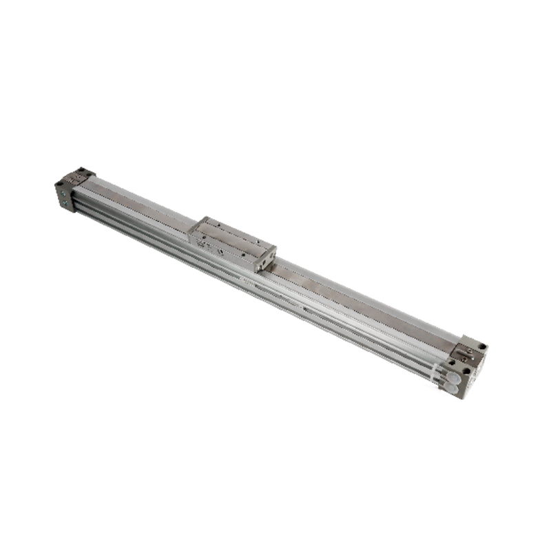 MY1B Series Mechanical Joint Rodless Cylinder (Basic Type) Suppliers, OEM/ODM FaCKT Pneumatic is a China wholesale MY1B Series Mechanical Joint Rodless Cylinder (Basic Type) suppliers and OEM/ODM factory, MY1B Series ...View Product →
| Design feature | Magnetic coupled | Mechanical joint |
|---|---|---|
| Load capacity | Low to medium | Medium to high |
| Typical stroke range | 100–3000 mm | 100–5000 mm |
| Slip risk under shock load | Yes | No |
| Sealing and dust behaviour | Clean, low leakage | Steel band wiper required |
| Relative cost | Lower | Higher |
Cushioning: Designing Out End-of-Stroke Shock
The end of the stroke is where most mechanical wear happens. At the end cap, the piston must dissipate the kinetic energy E = 0.5 × m × v². A 50 kg carriage moving at 0.5 m/s carries 6.25 joules of kinetic energy; without cushioning, that energy is absorbed in milliseconds by the cap and the seals.
| Cushioning type | Energy absorption | Typical use |
|---|---|---|
| Fixed rubber or polyurethane bumper | Low | Light loads, low speed |
| Adjustable pneumatic cushion | Medium | Standard automation at 0.1–0.6 m/s |
| Cushion plus speed control valve | Medium-high | Precise positioning and vertical loads |
| External hydraulic shock absorber | High | High speed, high mass, high cycle rates |
A practical rule: below 0.1 m/s with light loads, a rubber or polyurethane bumper is sufficient; from 0.1 to 0.5 m/s with moderate loads, adjustable pneumatic cushions are the standard; at higher speeds or with heavy loads, fit an external hydraulic shock absorber. Matching the cushioning to the actual kinetic energy is part of the cylinder design, not an afterthought.
Seals, Temperature and Air Quality
Seal material defines the operating window
Standard cylinders use NBR seals, typically rated from −20 °C to +80 °C. FKM (Viton) seals extend the upper limit to roughly 200 °C, which matters in drying lines and furnace-door applications. Polyurethane wipers are a common addition in dusty environments. The seal design also affects speed: U-cup seals give positive sealing at low speeds, while dynamic O-rings are preferred for high-speed cycling because they generate less friction.
Dirty air shortens cylinder life more than anything else
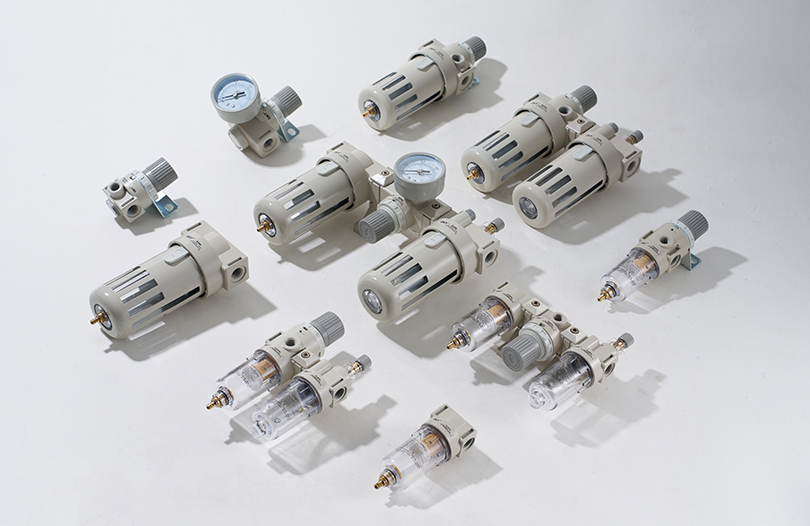
Most cylinder wear begins with contaminated compressed air. Water, residual compressor oil and fine particles score the tube and destroy rod seals. Installing a modular F.R.L. unit with a 5 µm filter and proper moisture separation at the point of use will do more for cylinder service life than changing the cylinder brand. Pressure, flow and sealing must be treated as a system, starting at the air preparation unit and ending at the exhaust port.
Standards That Shape Pneumatic Cylinder Design
Design is also about interchangeability. Nearly every pneumatic cylinder sold globally follows one of three ISO dimensional standards, and the construction family is usually dictated by the standard. The bore ranges below reflect the common industry interpretation used on the reference guidance in the Tameson pneumatic cylinder overview and equivalent sources.
| ISO standard | Typical bore range | Typical construction |
|---|---|---|
| ISO 6432 | 8–25 mm | Round body |
| ISO 15552 (formerly VDMA 24562) | 32–320 mm | Tie-rod or profile body |
| ISO 21287 | 20–100 mm | Compact or thin body |
Sourcing an ISO-compliant cylinder means a replacement unit from another brand will typically drop into the same mounts without redrawing the machine. A non-standard stroke or a custom rod length, by contrast, usually means a longer lead time and a higher price, so check the catalogue stroke range before freezing the design. With more than two decades of pneumatic component manufacturing experience, we build our standard and thin cylinder ranges to these conventions so that customers can switch suppliers without re-engineering the mounting.
A Pre-Order Checklist for Pneumatic Cylinder Design
Before a cylinder model is fixed, run through this checklist. Each item is a design input, and skipping one usually shows up as a field failure or a costly change order.
- Axial load for extend and retract, plus the 1.25–1.5 safety factor.
- Supply pressure available at the cylinder port, not just at the compressor.
- Stroke length equal to travel plus end margins.
- Speed and cycle time, with valve Cv and port sizes checked as one circuit.
- Mounting family selected for the direction of thrust and machine geometry.
- Side loads eliminated or transferred to a guided cylinder design.
- Cushioning matched to the kinetic energy at the end of stroke.
- Environment: temperature range, humidity, washdown or dust exposure.
- Position sensing: magnetic piston with a magnetic switch, or an external linear sensor.
- Maintenance plan: rebuildable tie-rod or replaceable cartridge cylinder.
Frequently Asked Questions About Pneumatic Cylinder Design
How do I calculate the force a pneumatic cylinder can produce?
Use F = P × A, where A is the effective piston area. For a 63 mm bore at 0.6 MPa, the theoretical extend force is 1,870 N. In practice, apply an efficiency of 75–90% to account for seal friction, then apply a safety factor of 1.25–1.5 for dynamic loads.
What bore size do I need for a 500 kg load?
A 500 kg load exerting roughly 4,900 N requires about 6,125 N of theoretical force at 0.6 MPa once an 80% efficiency is assumed. A 100 mm bore gives 4,712 N, which is not enough; a 125 mm bore gives 7,363 N, which is sufficient. Always verify the retract stroke too, because the rod reduces the effective area.
Which cylinder design is best for long strokes?
Rodless cylinders are the best choice for strokes above roughly 500 mm because the installation length is about half that of a rod-type cylinder. Use a magnetic coupled design for light, clean handling and a mechanically jointed design for heavier loads or vertical moves where slip is not acceptable.
Why does my cylinder fail from side loading even though the force is correct?
Because side loading creates a bending moment on the rod and front bearing that no amount of axial force can compensate for. Even a lateral force of a few percent of the rated thrust shortens bearing and seal life. The fix is to keep the thrust aligned with the rod centreline or use a guided cylinder design.
Can a standard pneumatic cylinder hold a load in mid-stroke?
No. Compressed air is compressible, so a standard double-acting cylinder cannot hold a fixed position under a varying load. Use a mechanical rod lock, a locking cylinder, or an external brake when mid-stroke holding is required.
What is the difference between single-acting and double-acting cylinder designs?
A single-acting cylinder uses air to move in one direction and a spring to return, which simplifies the circuit but limits stroke and consumes spring energy on the return. A double-acting cylinder uses air for both directions, giving full control of force, speed and cushioning in both directions — the standard choice for most automation.