

 中文简体
中文简体
 English



Content
- 1 Pneumatic Solenoid Valve Types: The Answer You Need First
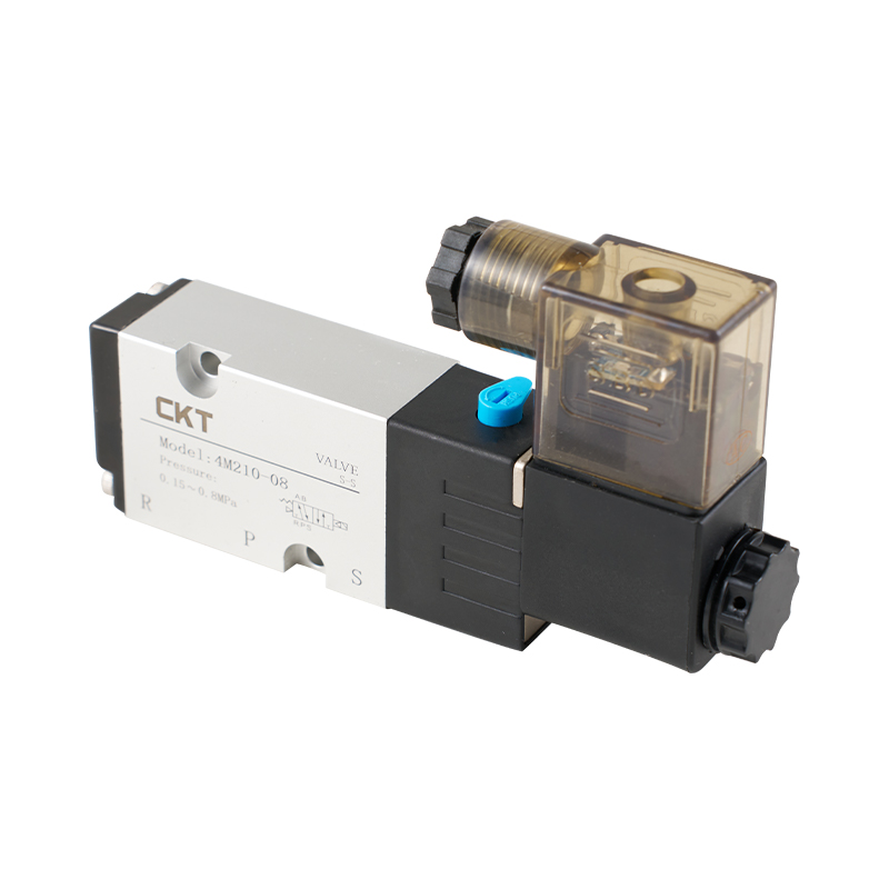
- 2 How a Pneumatic Solenoid Valve Works Before You Choose a Type
- 3 2/2-Way Pneumatic Solenoid Valves: Simple On/Off Flow Control
- 4 3/2-Way Pneumatic Solenoid Valves: Controlling Single-Acting Cylinders
- 5 5/2 and 5/3-Way Pneumatic Solenoid Valves: Double-Acting Cylinder Control
- 6 Direct-Acting vs Pilot-Operated vs Externally Piloted: Which Actuation Type Fits
- 7 Normally Open, Normally Closed, and Bistable Configurations
- 8 How to Choose the Right Pneumatic Solenoid Valve Type: Selection Criteria
- 9 Common Mistakes When Selecting Pneumatic Solenoid Valve Types
- 10 Frequently Asked Questions About Pneumatic Solenoid Valve Types
- 10.1 What does "2/2-way" or "5/2-way" mean in a pneumatic solenoid valve?
- 10.2 Which pneumatic solenoid valve type should I use for a single-acting cylinder?
- 10.3 Which pneumatic solenoid valve type should I use for a double-acting cylinder?
- 10.4 What is the difference between direct-acting and pilot-operated solenoid valves?
- 10.5 When should I pick a 5/3 valve instead of a 5/2 valve?
- 10.6 When do I need a bistable or double-solenoid valve?
- 10.7 Which voltage should I choose for a pneumatic solenoid valve?
- 10.8 Can I use an air solenoid valve for water or oil?
Pneumatic Solenoid Valve Types: The Answer You Need First
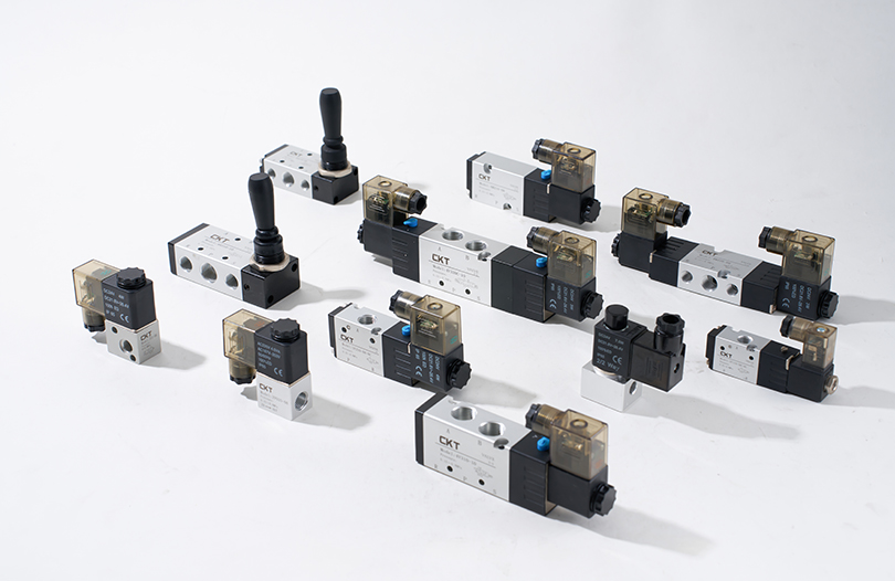
Put as simply as possible, there are four core pneumatic solenoid valve types to understand: 2/2-way, 3/2-way, 5/2-way, and 5/3-way valves. The first number is the number of working air ports; the second number is the number of spool positions. On top of that classification, every valve is also defined by its actuation method (direct-acting or pilot-operated) and by its rest-state behavior (normally open, normally closed, mono-stable, or bistable).
That combination is not academic. The four port-count types map directly onto four different jobs in a pneumatic circuit. A single-acting cylinder needs a 3/2-way valve. A double-acting cylinder needs a 5/2-way or 5/3-way valve. A simple air blow-off or supply shut-off line can be handled by a 2/2-way valve. When a machine stops mid-cycle, the cause is usually that one of these mappings was selected incorrectly.
| Valve Type | Ports / Positions | Solenoids | Typical Job | Example Series |
|---|---|---|---|---|
| 2/2-way | 2 ports / 2 positions | 1 | Simple on/off air supply, blow-off, venting | 2V025 |
| 3/2-way | 3 ports / 2 positions | 1 or 2 | Single-acting cylinder control | 3V1, 3V2, VT307 |
| 5/2-way | 5 ports / 2 positions | 1 or 2 | Double-acting cylinder control | 4V series |
| 5/3-way | 5 ports / 3 positions | 2 | Double-acting cylinder with defined mid-position | 4V (3-position) |
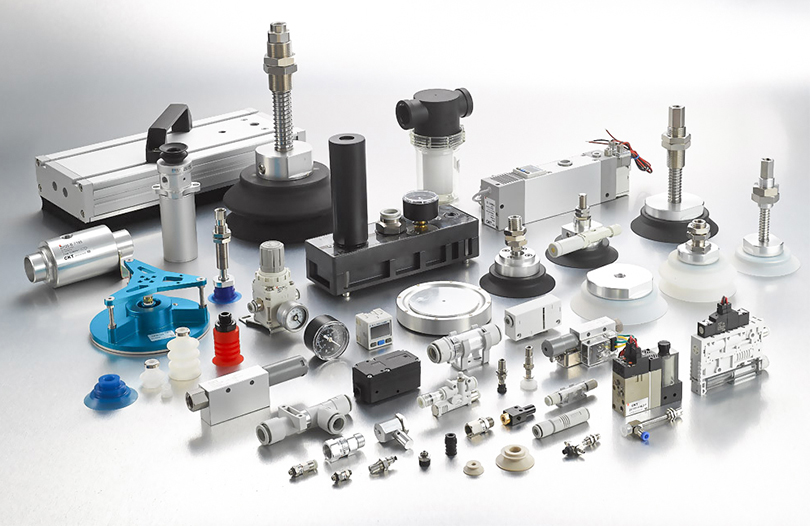
People often confuse a valve type with a specification. The type answers the question "how many ports, how many positions, how is it actuated, and what happens when power is off." The specification answers "which port size, which voltage, which Cv." You must resolve the type question first, because a 5/2 valve with a perfect Cv value will still not operate a single-acting cylinder correctly. The notation follows ISO 1219-1 for pneumatic circuit symbols, so a 5/2 valve drawn on a schematic always means five ports and two positions; reading the symbol correctly is the fastest way to identify a valve you have never seen before. CKT publishes its full solenoid valve and pneumatic component catalog online, which is a practical reference when you need to match a symbol to an actual model number.
How a Pneumatic Solenoid Valve Works Before You Choose a Type
Before comparing models, it helps to see what is inside the valve and why the internal construction determines the type. Every industrial solenoid valve contains the same core parts, but the way those parts interact decides whether it can operate at zero pressure, how much air it can pass, and how fast it responds.
- Solenoid coil and plunger: the coil converts electrical energy into a magnetic field that pulls the plunger, which moves the spool directly or through a pilot stage.
- Spool or poppet: a precision part that slides inside the valve body and redirects air between ports. Spool geometry defines the function of the valve.
- Return spring: pushes the spool back when the coil is de-energized. If the spring is present, the valve is mono-stable.
- Valve body: holds the ports, the bore, and the sealing surfaces. Most air valve bodies are aluminum alloy; fluid valves use stainless steel or brass.
- Seals and pilot channel: seals prevent cross-leakage between ports; in a pilot-operated valve, the pilot channel feeds air to the end of the spool to shift it.
- Manual override: a button or screw that lets you shift the valve by hand during commissioning, which is far more useful than many buyers expect.
Direct actuation vs pilot actuation in one paragraph
In a direct-acting valve, the coil moves the spool directly, so the valve can shift even when the inlet pressure is 0 MPa. The trade-off is limited flow, because the coil has to be big enough to overcome friction and air force. In a pilot-operated valve, a small solenoid shifts a pilot spool, and the inlet air itself pushes the main spool over. That design handles much higher flow with a compact coil, but it needs a minimum operating pressure, typically around 0.15 MPa. An externally piloted valve is the same idea, except the pilot air comes from a separate, regulated supply.
For industrial buyers, construction quality matters as much as the type. A spool machined to a looser tolerance leaks more pilot air, responds more slowly, and wears faster. CKT emphasizes its in-house manufacturing and assembly capabilities, with more than 20,000 types of semi-finished parts held in stock and over 90% of components machined internally. That level of vertical integration is what allows a valve manufacturer to keep spool-to-body clearances consistent across large production batches.
2/2-Way Pneumatic Solenoid Valves: Simple On/Off Flow Control
A 2/2-way valve has exactly two ports and two positions. In the normally closed version, the inlet port P is blocked in the rest state and connects to the outlet port A when the coil is energized. In the normally open version, P connects to A in the rest state and blocks when the coil is energized. Because it has only one outlet and no dedicated exhaust port, the 2/2-way valve is used for supply shut-off, blow-off, and venting, not for directional control of a cylinder by itself.
A typical application is a blow gun or a dust-cleaning nozzle where compressed air only needs to be switched on and off. Another is feeding a small slide mechanism that has its own exhaust path, or isolating a branch of a manifold during maintenance. If the device behind the valve cannot exhaust through another path, a 3/2-way valve is the correct choice instead.
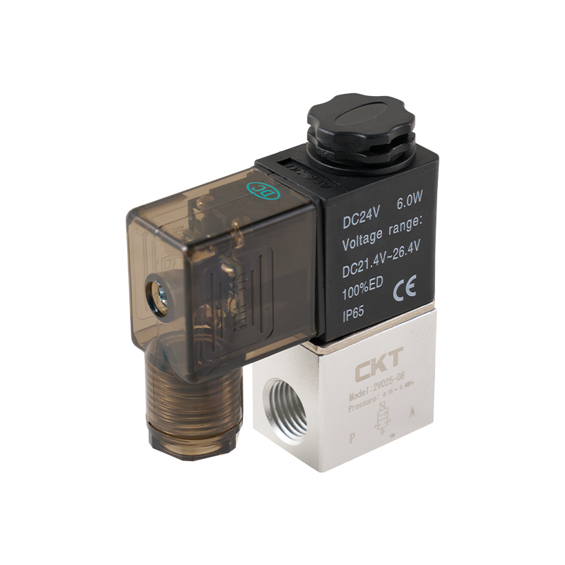
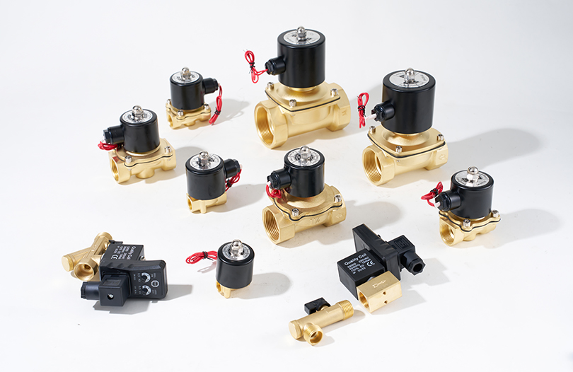
It is also important not to confuse a pneumatic 2/2 valve with a process 2/2 solenoid valve for liquids. Pneumatic 2/2 valves like the 2V025 are designed for compressed air circuits. For water, oil, or gas media, CKT separately offers the 2S stainless steel series and the 2W copper series under its process valve category, because the seal materials and flow paths are engineered for fluid media rather than air. For a compact, low-flow air on/off application, the direct-acting 2/2-way solenoid valve is the most common starting point: its 1/8-inch port and short body allow it to be mounted close to the point of use, and because it is direct-acting, it functions even when the incoming air pressure is very low.
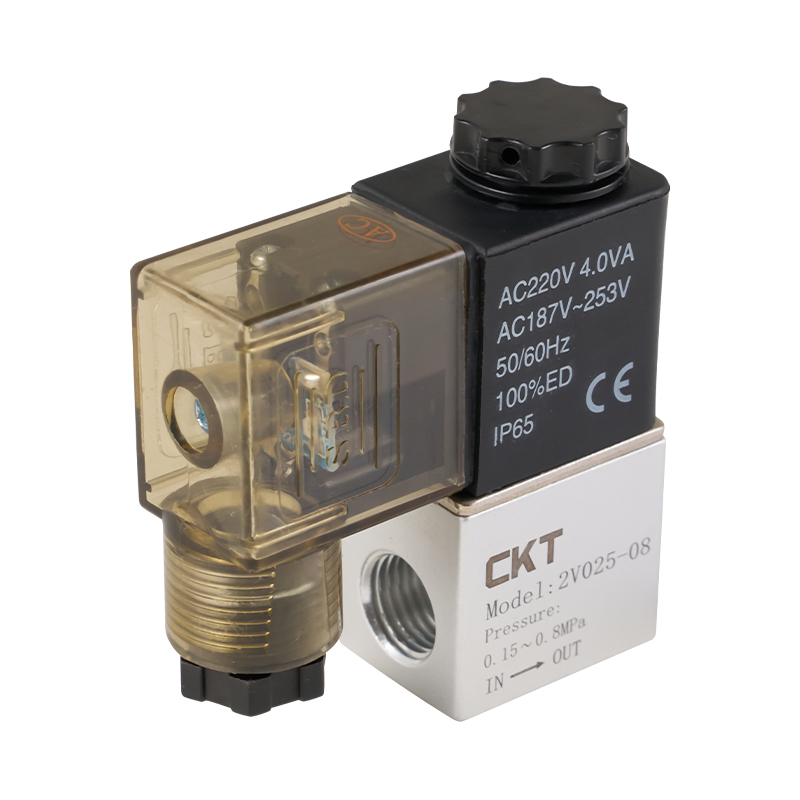 2V025 Series Direct Acting 2 Way Solenoid Valve Suppliers, OEM/ODM Factory - ZheCKT Pneumatic is a China wholesale 2V025 Series Direct Acting 2 Way Solenoid Valve suppliers and OEM/ODM factory, The 2V025 series is a c...View Product →
3/2-Way Pneumatic Solenoid Valves: Controlling Single-Acting Cylinders
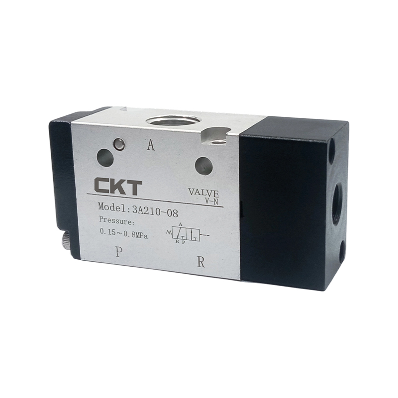
A 3/2-way valve has three ports (pressure P, cylinder A, exhaust R) and two positions. It is the standard directional control valve for a single-acting cylinder. In one position, supply flows to the cylinder to extend it; in the other position, supply is blocked and the cylinder port connects to exhaust so the internal spring can retract the rod.
In a normally closed 3/2 valve, the cylinder is exhausted when power is off and pressurizes when energized. In a normally open 3/2 valve, the cylinder is pressurized when power is off. For machines where a cylinder must stay extended during a power cut, a normally open or a latching valve is the deliberate choice. For most standard automation routines, normally closed is the safer default because the actuator relaxes to a known position when the machine stops.
Direct-acting vs pilot-operated 3/2 valves
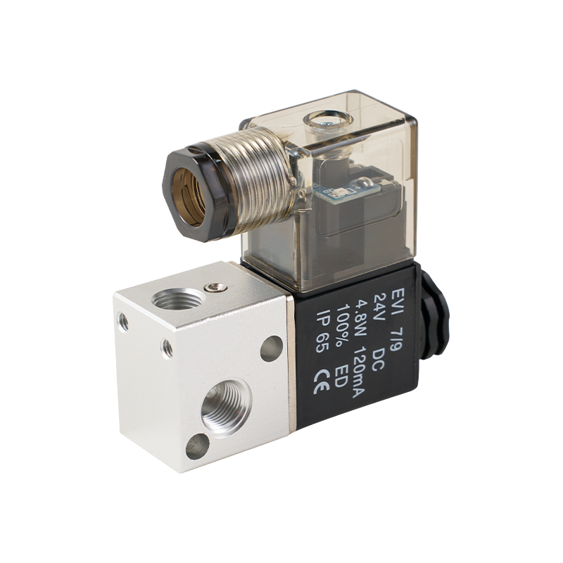
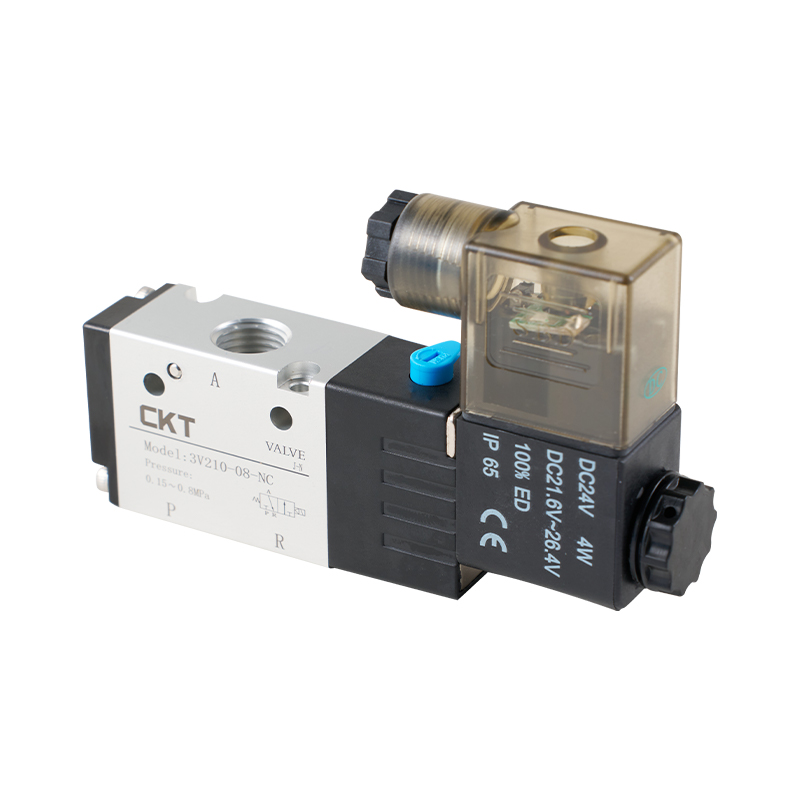
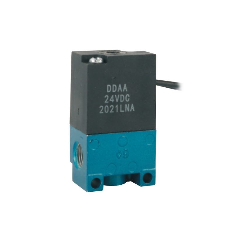
Direct-acting 3/2 valves such as the 3V1 and 3V2 series shift the spool using only the solenoid, so they work from 0 MPa inlet pressure. They respond quickly and are ideal for small bores and low-flow circuits. Pilot-operated 3/2 valves such as the 3V series use inlet pressure to assist the shift and suit higher-flow circuits, but they require a supply pressure above roughly 0.15 MPa. There is also the VT307 series, a direct-acting seat-valve construction with a poppet-style internal design that is often used in clamping and tooling circuits. CKT additionally offers the 35 series (MAC-type) and 3PA series (SELEX-type) direct-acting 3-way valves, which are selected when a customer needs to match an existing machine footprint or control convention.
If you are sizing a straightforward 3/2 circuit for a small single-acting cylinder, choosing a direct-acting 3/2-way solenoid valve keeps the construction simple and the response immediate. The lack of a minimum pressure requirement also makes commissioning easier on machines with uncertain shop-air pressure at startup.
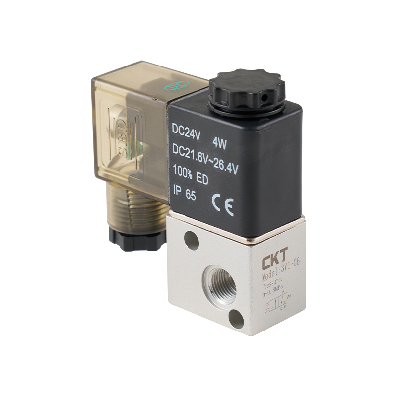 3V1 Series Direct Acting 3 Way Solenoid Valve Suppliers, OEM/ODM Factory - ZhejiCKT Pneumatic is a China wholesale 3V1 Series Direct Acting 3 Way Solenoid Valve suppliers and OEM/ODM factory, The 3V1 series represents...View Product →
5/2 and 5/3-Way Pneumatic Solenoid Valves: Double-Acting Cylinder Control
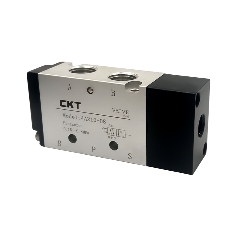
A 5/2-way valve has five ports: one pressure inlet P, two cylinder ports A and B, and two exhaust ports usually labeled R1 and R2 or EA and EB. The two positions flip the supply between A and B, which is exactly what a double-acting cylinder needs. The single-solenoid version is spring-returned (mono-stable); the double-solenoid version latches in the last position (bistable) and holds the cylinder at the end of its stroke even if electrical power is lost.
The 5/3-way valve adds a third, center position and is always a double-solenoid valve. The center position defines what happens when both solenoids are de-energized, and it changes the behavior of the machine more than most engineers expect. The table below summarizes the three standard center configurations.
| Center Type | Port P | Ports A and B | Effect on Cylinder | Typical Use |
|---|---|---|---|---|
| All ports blocked (closed center) | Closed | Closed | Piston locks in position; no air moves in or out | Stopping mid-stroke, clamping |
| Exhaust center | Closed | Both to exhaust | Piston floats; rod can be moved by hand | Loading and unloading, energy saving |
| Pressure center | Open to A and B | Both pressurized | Both sides see supply pressure; a single-rod cylinder tends to extend slightly due to area difference on the rod side | Circuits that must always keep pressure on the actuator; higher air consumption |
The closed center is the most common 5/3 choice because it gives a rigid mid-position stop. However, over a long period, spool and seal leakage can cause the cylinder position to drift, so the closed center should not be treated as a mechanical lock. If the load must be held indefinitely without leakage, use an external mechanical brake or a check valve rather than relying only on valve sealing.
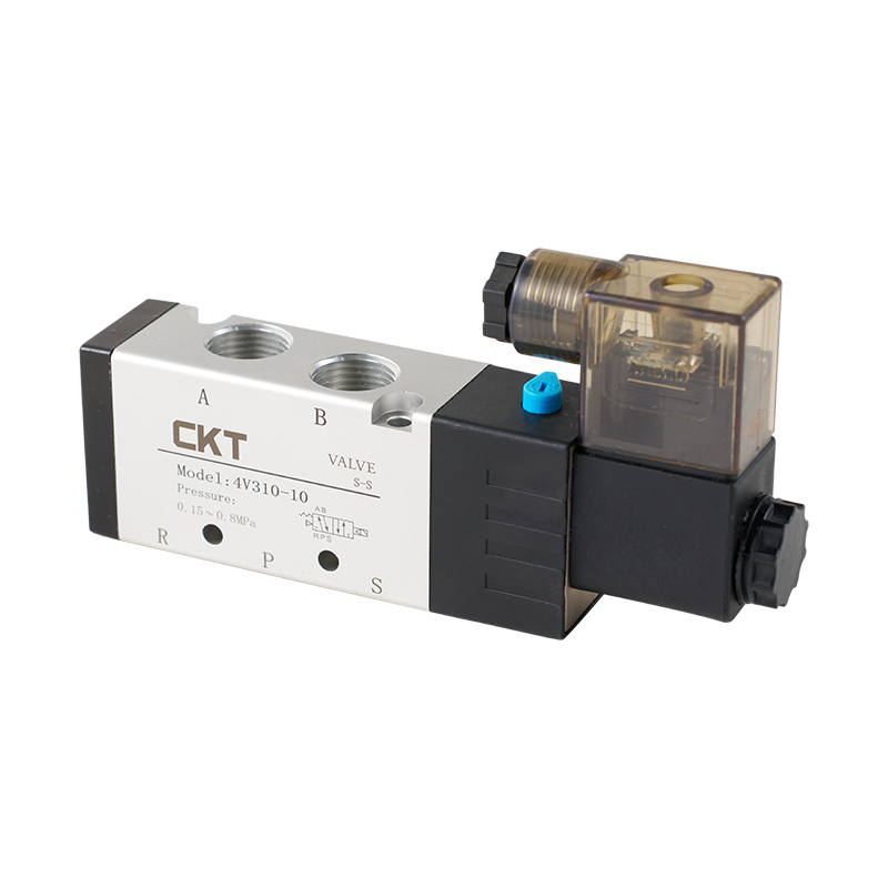
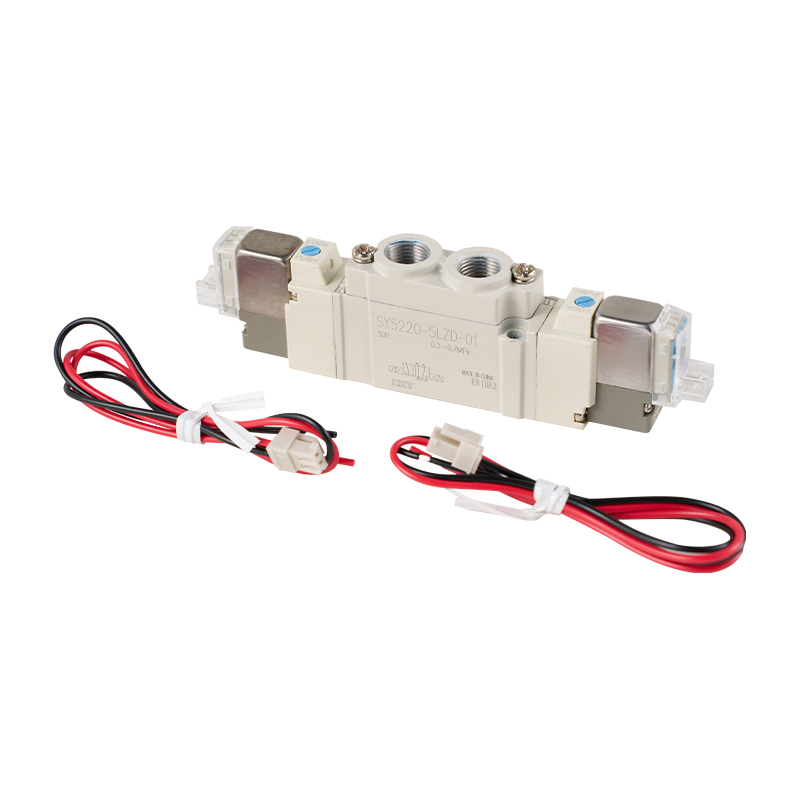
In manufacturing lines, 5/2 and 5/3 valves are often mounted on a manifold sub-base so that several valves share one supply and exhaust block. This arrangement simplifies tubing, reduces leak points, and makes wiring more organized. CKT's pilot-operated 5/2-way solenoid valve series covers the 4V110 to 4V410 size range with ports from G1/8 to G1/2, and the same body platform is also configured as a 5/3 valve by fitting a three-position spool and double solenoids. That interchangeability is useful when a machine design changes late in the project.
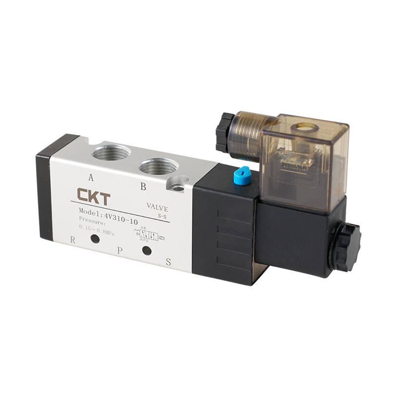 4V Series Pilot Operated 5 Way Solenoid Valve Suppliers, OEM/ODM Factory - ZhejiCKT Pneumatic is a China wholesale 4V Series Pilot Operated 5 Way Solenoid Valve suppliers and OEM/ODM factory, 4V series pilot operated ...View Product →
Direct-Acting vs Pilot-Operated vs Externally Piloted: Which Actuation Type Fits
After choosing the port count, the next decision is the actuation method. This choice determines the minimum working pressure, the maximum flow, and sometimes the physical size of the valve. The table below compares the three main options on the parameters that actually affect sizing.
| Feature | Direct-Acting | Internally Piloted | Externally Piloted |
|---|---|---|---|
| Minimum working pressure | 0 MPa (0 bar) | About 0.15 MPa | Main port from 0 MPa; pilot supply about 0.2 to 0.3 MPa |
| Flow capacity | Lower, limited by coil force | Higher, limited by body port size | Higher, same as internally piloted |
| What shifts the spool | Solenoid force alone | Inlet air pressure assisted by solenoid pilot | Separate pilot air supply |
| Best suited for | Small bores, low flow, zero-pressure circuits, compact machines | General factory air at 0.4 to 0.7 MPa, larger cylinders | Low or unstable main pressure, or when pilot air must be clean and regulated |
The practical rule is straightforward. If the supply pressure might drop below the pilot threshold during startup or machine jams, a direct-acting valve is more forgiving. If the application demands a high flow rate from a compact valve, pilot operation is the standard solution. If the main inlet pressure is very low but the process still needs a large directional valve, an externally piloted valve lets you use a small regulated pilot pressure to shift a big spool while the main flow operates at whatever pressure the process provides.
Normally Open, Normally Closed, and Bistable Configurations
The rest state of the valve matters for two reasons: safety and energy consumption. A valve that returns to a known position when power fails can prevent a dropped load, an unexpected cylinder movement, or a tool crash. A valve that latches in its last position may be exactly what the process needs, but it requires a careful safety review.
Normally open vs normally closed
In a normally closed valve, no flow passes in the rest state. This is the safer default for most automation because actuators relax to a defined position. In a normally open valve, flow passes in the rest state. This suits functions that must remain active when power is off, such as keeping a coolant nozzle open or continuously venting a pressure line. The choice is not about performance; it is about defining what the machine should do during an outage.
Mono-stable vs bistable (latching)
A mono-stable valve has one solenoid and a return spring: when power is removed, the spring resets the spool immediately. A bistable valve has two solenoids and no return spring: the spool stays in the last position it was shifted to, even with the power disconnected. The coil draws current only during the switching pulse, which means less heat generation, lower energy consumption, and no continuous coil burnout risk in a stalled state.
A typical example is a double-solenoid 5/2 valve driving a clamping cylinder. If the power dies mid-cycle, the cylinder holds its current clamping state, which may protect the workpiece. The same behavior, however, means the machine restarts in an unknown state. If the restart sequence does not first command both solenoids, an unexpected movement can occur. For this reason, bistable valves are common in battery-powered equipment and in systems where the actuator position must be retained during short power interruptions, but they require a well-written control sequence.
How to Choose the Right Pneumatic Solenoid Valve Type: Selection Criteria
Once the type is clear, the remaining work is specification. The checklist below follows the order most pneumatic engineers actually use when they size a valve for a new machine.
- Identify the actuator. Single-acting cylinder: 3/2-way. Double-acting cylinder: 5/2-way, or 5/3-way if a defined mid-position is required.
- Decide the rest state. Choose normally open or normally closed for 2/2 and 3/2 valves; choose mono-stable or bistable for 5/2 valves; choose the center configuration for 5/3 valves.
- Check the minimum operating pressure. Pilot-operated valves need roughly 0.15 MPa. If the circuit can fall below this, switch to direct-acting or add a regulator before the valve.
- Match voltage and coil type. 24 VDC is the standard for PLC-based machines. AC coils are still common in retrofits but need to be matched exactly to the control circuit.
- Calculate the flow coefficient (Cv). Larger Cv means more air flow and faster cylinder movement. Estimate from cylinder bore, stroke, and required cycle time instead of guessing.
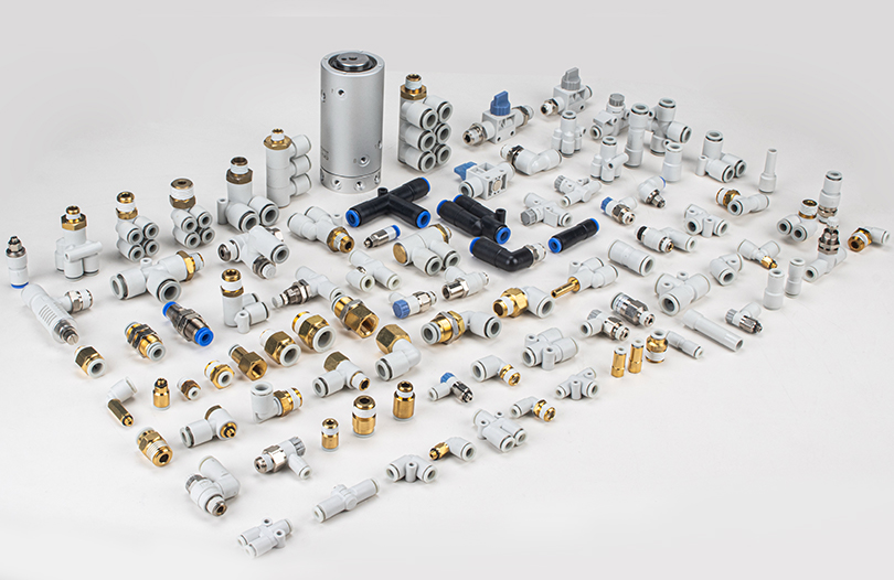
- Select port size and connection. Threaded ports (G1/8, G1/4, etc.), push-in one-touch fittings, or sub-base mounting all change the physical layout.
- Verify the response time. Direct-acting valves typically respond in the 10 to 20 ms range; pilot-operated valves in the 20 to 50 ms range. For very high cycle rates, this matters as much as Cv.
- Account for environment. Ambient temperature, humidity, dust, and IP protection rating affect seal life and coil reliability.
When you combine the valve rating with the rest of the preparation units, the same engineering logic applies upstream too. A practical reference is this analysis of pressure matching and installation sealing, which explains how the filter-regulator-lubricator set, the valve pressure range, and the fittings interact in a real circuit. It is a common source of hidden failures when a valve is rated correctly but the surrounding components are not.
| Parameter | Typical Range | Selection Tip |
|---|---|---|
| Working pressure | 0.15 to 0.8 MPa for pilot; 0 to 1.0 MPa for direct-acting | Check the minimum, not just the maximum. |
| Port size | M5, G1/8, G1/4, G3/8, G1/2 | Match the port to the tubing and cylinder port, not the other way around. |
| Cv value | 0.2 to 0.4 for small direct-acting; 0.4 to 2.4 for 5/2 pilot-operated | Use Cv to estimate speed; oversizing wastes air, undersizing slows the machine. |
| Voltage | 24 VDC, 12 VDC, 110 VAC, 220 VAC | 24 VDC is the practical default for modern PLC control. |
| Response time | 10 to 50 ms | Critical for pick-and-place cycles above 60 cycles per minute. |
| Operating temperature | -5 °C to 60 °C for standard air valves | Derate or add a heater in cold rooms and outdoor cabinets. |
| Coil power | 2 to 3 W at 24 VDC; 4 to 5 VA at AC | Confirm the PLC output or valve driver can supply the inrush current. |
Common Mistakes When Selecting Pneumatic Solenoid Valve Types
Several recurring mistakes show up again and again in machine commissioning reports and maintenance logs. The table below summarizes what goes wrong, what symptom you will see on the machine, and the correction.
| Mistake | Machine Symptom | Correction |
|---|---|---|
| Using a 3/2 valve on a double-acting cylinder | Cylinder extends but does not retract under control | Replace with a 5/2-way valve. |
| Internally piloted valve with supply below 0.15 MPa | Spool never shifts; coil energizes but no cylinder movement | Use a direct-acting valve or an external pilot supply. |
| Wrong coil voltage | Coil burns quickly, or the spool does not have enough pull | Match coil voltage to the control output with proper tolerance. |
| Cv too low for the required cycle time | Cylinder moves slowly or the cycle time drifts | Oversize to the next valve class or reduce exhaust restriction. |
| NO and NC swapped | Machine starts with the cylinder extending instead of retracting | Define the fail-safe action before ordering; check the rest-state drawing. |
| Port and fitting mismatch | Leakage at the connection, reduced flow, damaged threads | Confirm the exact port thread standard and use matching fittings. |
Most of these failures are avoidable with a short review of the valve symbol, the actuator type, and the supply pressure before ordering. If the machine already exists and the problem appears during commissioning, check the valve symbol stamped on the body first; it is faster than replacing parts blindly.
Frequently Asked Questions About Pneumatic Solenoid Valve Types
What does "2/2-way" or "5/2-way" mean in a pneumatic solenoid valve?
The first number is the number of working air ports, and the second number is the number of spool positions. A 5/2 valve therefore has five ports (pressure, two cylinder ports, and two exhausts) and two positions. A 3/2 valve has three ports and two positions.
Which pneumatic solenoid valve type should I use for a single-acting cylinder?
Use a 3/2-way valve. It pressurizes the cylinder port to extend the rod and then connects the same port to exhaust so the internal spring can retract it. A normally closed 3/2 valve is the standard default.
Which pneumatic solenoid valve type should I use for a double-acting cylinder?
Use a 5/2-way valve for standard extend and retract operation. Use a 5/3-way valve if the cylinder must also stop mid-stroke or float in a defined center position.
What is the difference between direct-acting and pilot-operated solenoid valves?
A direct-acting valve moves the spool using only the coil, so it works from 0 MPa but passes less air. A pilot-operated valve uses the inlet air pressure to move the main spool, which allows higher flow, but it needs a minimum operating pressure of roughly 0.15 MPa.
When should I pick a 5/3 valve instead of a 5/2 valve?
Choose a 5/3 valve when the cylinder must stop mid-stroke, float, or stay pressurized in the middle. The center type makes a big difference: closed center locks the piston, exhaust center lets it float, and pressure center keeps both ports pressurized with higher air consumption.
When do I need a bistable or double-solenoid valve?
Use a double-solenoid valve when the actuator must hold its last position after a power loss and when you want to reduce continuous coil heating. Keep in mind that there is no spring to reset the spool, so the machine may restart in an unknown state.
Which voltage should I choose for a pneumatic solenoid valve?
24 VDC is the most common choice for modern PLC-controlled machines because it is safe, simple to drive, and easy to protect with surge-suppression diodes. AC versions at 110 VAC or 220 VAC still exist for legacy control panels but require careful matching of the coil to the supply.
Can I use an air solenoid valve for water or oil?
No. Air solenoid valves use seals and flow paths designed for compressed air. For water, oil, or gas media, use dedicated fluid solenoid valves such as CKT's 2S stainless steel series or 2W copper series, which have media-compatible seals and body materials.