

 中文简体
中文简体
 English


Content
- 1 Pneumatic Cylinder Basics: What You Need to Know First
- 2 Core Components and Their Functions
- 3 Main Types of Pneumatic Cylinders
- 4 Key Selection Parameters for Pneumatic Cylinders
- 5 Pneumatic Cylinder Force Calculation with Real Example
- 6 Mounting Options and Installation Best Practices
- 7 Common Applications Across Industrial Sectors
- 8 Maintenance and Troubleshooting Guide
- 9 Frequently Asked Questions About Pneumatic Cylinders
- 9.1 Q1: What is the difference between single-acting and double-acting pneumatic cylinders?
- 9.2 Q2: How do I calculate the force of a pneumatic cylinder?
- 9.3 Q3: What is a rodless cylinder and when should I use it?
- 9.4 Q4: How do I choose the correct bore size for my application?
- 9.5 Q5: What is the typical service interval for a pneumatic cylinder?
- 9.6 Q6: Can pneumatic cylinders withstand high-temperature environments?
- 9.7 Q7: What are the main advantages of pneumatic cylinders over electric actuators?
- 9.8 Q8: How do I reduce shock and noise at the end of cylinder stroke?
Pneumatic Cylinder Basics: What You Need to Know First
A pneumatic cylinder is a mechanical actuator that converts compressed air energy into linear force and motion. It is the most widely used final control element in automated manufacturing systems, with an estimated global market value of approximately $5.6 billion as of 2026 and annual shipments exceeding 85 million units across automotive, packaging, food processing, and semiconductor industries. (Source: Global Industrial Actuator Market Analysis, 2026)
The direct answer to "what is a pneumatic cylinder?" is that it is a simple, reliable, and cost-effective device for converting air pressure into straight-line movement. Unlike electric linear actuators, pneumatic cylinders deliver high force-to-size ratios, operate safely in flammable environments, and tolerate shock loads without damaging internal components. These characteristics make them the default choice for pushing, pulling, clamping, lifting, and sequencing operations in industrial machines.
For procurement engineers and automation designers, choosing the right pneumatic cylinder is not just about picking a catalogue item. It directly impacts cycle time, product quality, machine uptime, and total cost of ownership. The decisions you make today about bore size, stroke, mounting style, and seal material will affect your equipment for years to come. This guide covers the core technical facts you need to specify the correct cylinder for your application, including latest industry standards and CKT Pneumatic's product lineup that has been refined since 2002.
Core Components and Their Functions
A pneumatic cylinder is built from several precision-machined components that work together to create smooth, repeatable linear motion. Understanding each component's role helps you diagnose failures and select better quality products. CKT Cylinder manufacturing uses 90% in-house production for its cylinder components, maintaining strict quality control from raw material to final assembly.
| Component | Function | Common Material |
|---|---|---|
| Cylinder Barrel | Houses the piston and defines the bore diameter | Aluminum alloy, stainless steel |
| Piston | Seals against the barrel and transfers pressure force to the rod | Aluminum alloy |
| Piston Rod | Transmits linear force to the external load | Hard chrome-plated steel or stainless steel |
| End Caps | Seal the cylinder ends, house rod seals and port connections | Die-cast aluminum |
| Seals | Prevent leakage; different types for rod, piston, and static sealing | NBR, Polyurethane, Viton |
| Cushioning Mechanism | Absorbs kinetic energy at stroke end to prevent shock | Built-in or adjustable cushion ring |
In CKT's manufacturing facility, more than 20,000 semi-finished component variants are stored in inventory to support fast delivery across the complete cylinder range. This in-house capacity means consistent quality and shorter lead times for both standard and modified cylinders.
Main Types of Pneumatic Cylinders
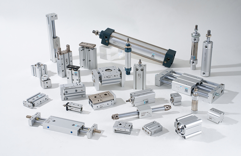
Pneumatic cylinders come in several architectures. The type you choose determines motion precision, force output, space efficiency, and maintenance needs. The three most common categories in industrial automation are single-acting, double-acting, and rodless cylinders. CKT's air cylinder catalogue covers all three plus compact, multi-axis, rotary, and slide variants.
Single-Acting Cylinders
Single-acting cylinders use compressed air for the outstroke and rely on an internal spring for the return stroke. They are compact, inexpensive, and ideal for clamping, positioning, and short-stroke push operations. However, because part of the piston force goes into compressing the spring, they deliver only about 50% to 60% of the force of an equal-bore double-acting cylinder. Typical bore sizes range from 8mm to 63mm with strokes from 5mm to 150mm.
Double-Acting Cylinders
Double-acting cylinders apply compressed air to both sides of the piston, producing force in both directions. They represent approximately 75% of all pneumatic cylinder installations due to their versatility and higher force density. Standard bore sizes span 16mm to 200mm, with stroke lengths from 10mm to over 2500mm. For heavy-duty automation, tie-rod cylinders like CKT's SC series provide robust construction with interchangeable seal kits. 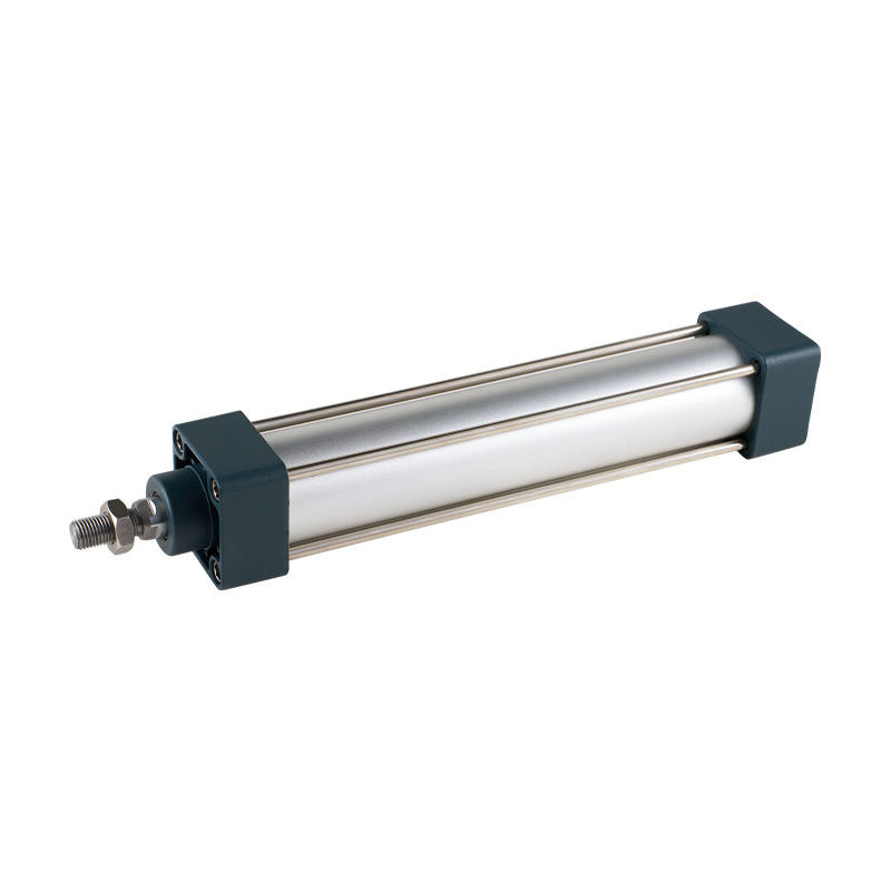 CKT SC Series Tie Rod Standard CylinderThe SC series is a robust tie-rod cylinder with a compact length compared to ISO15552. It offers stable cushioning, high-temperature sealing up to 150°C, and multiple mounting options, making it reliable for heavy-duty automation.View Product →
Rodless Cylinders
Rodless cylinders remove the external piston rod completely. The piston is coupled to a slider through a magnetic field or a mechanical slot, allowing the load to travel along the cylinder body. This design saves up to 50% of installation length compared to standard rod-type cylinders and eliminates rod buckling risks in long-stroke applications. They are particularly well suited for horizontal load transfer, automated sorting, and conveyor routing. CKT's CY1S series magnetic-coupled rodless cylinders use sliding bearing support for smooth, low-friction movement and are available with stroke lengths up to 1000mm. 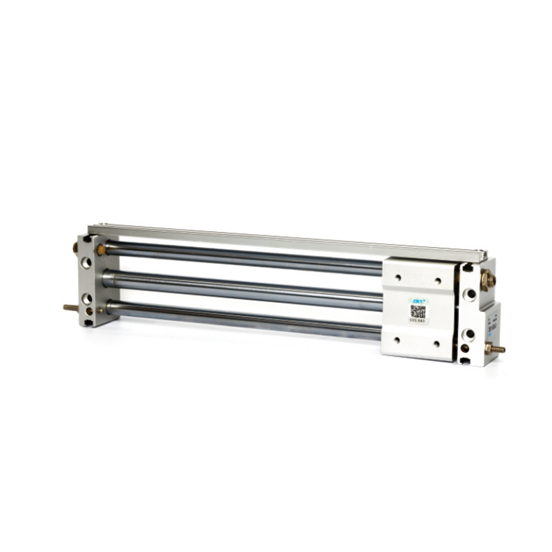 CKT CY1S Magnetic Coupled Rodless CylinderThe CY1S series uses a sliding bearing and magnetic coupling to save space and isolate contaminants. It provides smooth, low-friction motion with long lubrication intervals, ideal for dusty or light-splatter environments.View Product →
Thin and Compact Cylinders
Thin cylinders, also called compact cylinders, feature a reduced axial profile that fits into space-constrained fixture designs. They are widely used in gripper assemblies, clamping stations, and machine tool loaders. CKT's CQ2 series thin cylinders offer bore sizes from 12mm to 100mm and stroke lengths from 5mm to 100mm, providing high force output in a low-form-factor package. 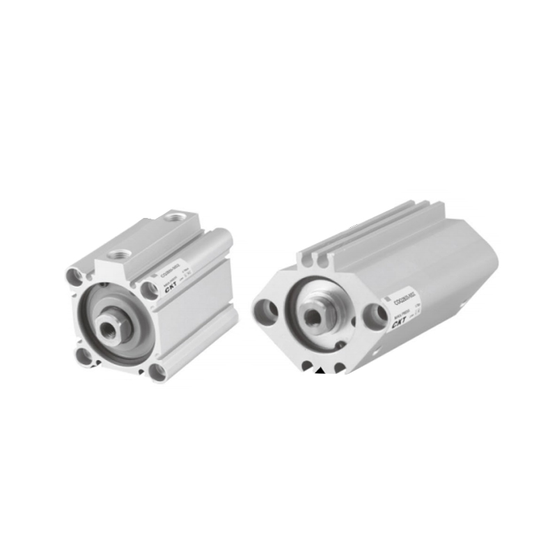 CKT CQ2 Series Thin Compact CylinderThe CQ2 thin cylinder fits tight spaces with a low profile. Its non-protruding magnetic switch improves safety and water resistance, suitable for grippers and clamping stations in constrained tooling.View Product →
You can also explore CKT's technical article that explains the secrets behind the power of pneumatic air cylinders, which covers internal construction details that affect performance and longevity.
Key Selection Parameters for Pneumatic Cylinders
Specifying the perfect cylinder requires evaluating six critical parameters. Getting these wrong causes additional cost, wasted floor space, or premature failure. Here is a practical selection checklist based on CKT's engineering guidance for 2026.
- Bore Size: Determines the force output. A 32mm bore cylinder at 0.6 MPa delivers approximately 482N of theoretical force. For a 63mm bore at the same pressure, the theoretical force jumps to about 1,870N.
- Stroke Length: Must exactly match required travel. Always add extra stroke length, typically 10mm to 20mm, for cushioning and minor load variations during installation.
- Operating Pressure: Standard industrial range is 0.4 to 0.7 MPa. CKT pneumatic cylinders are pressure-tested up to 1.0 MPa to ensure a safe safety margin.
- Operating Speed: Most pneumatic cylinders run between 50mm/s and 500mm/s. Speeds above 500mm/s require proper cushioning to prevent end-of-stroke shock.
- Load Direction: Side loads on the piston rod accelerate seal wear and can bend the rod. If the load is lateral, consider guided cylinders (multi-axis or slide cylinders).
- Environment: For temperatures above 60 degree Celsius, use Viton seals. For washdown environments, choose stainless steel or nickel-plated barrels.
| Application Scenario | Primary Selection Driver | Recommended Cylinder Type |
|---|---|---|
| Clamping / Positioning | Compactness | Thin cylinder (CQ2) |
| Heavy pushing / Pulling | Force | Tie-rod standard (SC) |
| Long-stroke transfer | Space saving | Rodless cylinder (CY1S) |
| Gripping / Pick-and-place | Side load resistance | Multi-axis or guided cylinder |
| High-speed sorting | Low friction / Fast actuation | Magnetic rodless (CY1L) |
Pneumatic Cylinder Force Calculation with Real Example
The theoretical force of a pneumatic cylinder is derived directly from pressure and piston area:
F = P x A
Where F is the force in Newtons, P is the gauge pressure in Pascals, and A is the effective piston area in square meters.
Let's calculate for a 40mm bore double-acting cylinder at 0.6 MPa operating pressure:
- Effective piston area A = pi x (diameter / 2) squared = 3.1416 x (0.02m) squared = 0.001257 square meters
- Theoretical outstroke force F = 0.6 x 10 to the power of 6 Pa x 0.001257 = 754 N
- Considering friction losses of 10% to 15%, the actual usable force ranges from 640 N to 716 N
For the instroke where the rod is retracting, the effective area is reduced by the rod's cross-sectional area. With a 12mm rod, the instroke area becomes 0.001136 square meters, yielding a theoretical instroke force of 682 N, or about 10% less than the outstroke. These calculations match the standard sizing formulas found in ISO 6432 and ISO 15552 technical specifications. (Source: ISO 6432:2025 Pneumatic fluid power standard)
Mounting Options and Installation Best Practices
Mounting style has a direct impact on cylinder alignment, load capacity, and seal life. Installing a cylinder with misaligned loads can reduce its service life by up to 60% because side forces cause rapid rod seal wear and rod bending.
Rear Flange| Mounting Type | Best For | Notes |
|---|---|---|
| Centerline Mount | Tie-rod and flange cylinders | Best stability; aligns force exactly with cylinder centerline |
| Side Mount | Space-constrained installations | Avoid side loads; use guided or slide cylinders if lateral force exists |
| Pivot Mount | Applications with changing load angles | Compensates for small misalignment; check pivot pin clearance |
| Fixed push applications | Provides rigid support; ensure flange is parallel to the load direction |
For installation, always follow the manufacturer's recommended bolt torque. A typical M8 mounting bolt for an SC series cylinder should be tightened to 20 N-m. Overtightening distorts the cylinder body and causes piston binding. You can also review CKT's guide on pneumatic component pressure matching and installation sealing for deeper technical context.
Common Applications Across Industrial Sectors
Pneumatic cylinders are the workhorses of modern manufacturing. Their applications cover a wide spectrum from simple fixture clamping to high-speed precision handling.
- Automotive Assembly: Gripping and transferring car body panels on conveyor systems. A 63mm bore cylinder at 0.6 MPa generates approximately 1,870N, sufficient for handling sheet metal fixtures.
- Packaging: Pushing boxes onto pallets, sealing cartons, and operating packing station gates.
- Food Processing: Controlled clamping and cutting operations in stainless steel or washdown-rated housing.
- Semiconductor Equipment: Precision positioning where magnetic interference from electric actuators could compromise sensitive processes.
- Woodworking: Clamping and pressing in CNC routing and panel cutting machines.
- Textile Machinery: Tensioning and thread guiding in high-speed weaving lines.
In a typical packaging line, a double-acting cylinder with a 63mm bore at 0.5 MPa can generate approximately 1,560N of force, which is enough to push heavy cartons onto a pallet without modification over millions of cycles. CKT's application engineering data from 2026 confirms that properly lubricated pneumatic cylinders on such lines achieve over 100 million cycles before seal replacement. (Source: CKT Pneumatic internal qualification test data, 2026)
Maintenance and Troubleshooting Guide
A well-maintained pneumatic cylinder can realistically achieve 2,000 to 10,000 kilometers of rod travel before requiring major service. Achieving this lifespan depends on three factors: air quality, alignment precision, and seal maintenance.
Routine Maintenance Checklist
- Check air treatment system (filter, regulator, lubricator) monthly for pressure drops and moisture.
- Inspect rod seals visually during machine maintenance windows; replace seals every 12 to 18 months or 10 million cycles, whichever comes first.
- Ensure the compressed air quality is better than ISO 8573-1 Class 3/4/4 to minimize seal wear.
- Clean the rod surface with a lint-free cloth during scheduled shutdowns.
- Check mounting bolts for loosened torque after the first week of operation and annually thereafter.
Troubleshooting Common Problems
| Symptom | Root Cause | Solution |
|---|---|---|
| Slow or jerky movement | Restricted flow or low air supply | Check flow control valves, increase tube diameter |
| External air leakage | Worn rod seal or end cap gasket | Replace seal kit; inspect for rod scratches |
| Cylinder drifts when stopped | Leakage past piston seal or valve | Replace piston seal; check directional valve |
| Rod bent or scored | Excessive side load or misalignment | Correct alignment; use guided cylinder |
| Excessive noise at stroke end | Cushioning malfunction or air trapped | Adjust cushion needle; bleed trapped air |
Frequently Asked Questions About Pneumatic Cylinders
Q1: What is the difference between single-acting and double-acting pneumatic cylinders?
Single-acting cylinders use compressed air for one direction of motion and a spring for the return. Double-acting cylinders use compressed air for both directions, producing force on both outstroke and instroke. For automation applications that require control on both strokes, double-acting cylinders are the standard choice because they offer full force output and precise speed regulation in both directions.
Q2: How do I calculate the force of a pneumatic cylinder?
Use the formula F = P x A, where P is pressure in Pascals and A is the piston area in square meters. Multiply that by an efficiency factor of 0.85 to 0.90 to account for friction. For a 50mm bore cylinder at 0.5 MPa, the theoretical outstroke force is about 982N, and the practical force is approximately 835N to 884N.
Q3: What is a rodless cylinder and when should I use it?
A rodless cylinder uses a magnetic or mechanical coupling between the piston and an external slider, eliminating the piston rod. You should use it when the installation length is limited, when long strokes are needed, or when rod buckling would be a concern. A typical rodless cylinder is about 50% shorter than its rod-type equivalent at the same stroke.
Q4: How do I choose the correct bore size for my application?
Start with the load force, then divide by the operating pressure to determine the required piston area. Add a safety margin of 20% to 30% to account for friction and unexpected side loads. For example, moving a 200kg load with a coefficient of friction of 0.5 at 0.5 MPa produces a required force of 981N, which corresponds to a minimum bore size of 50mm. Select the next standard bore size upward, which in this case would be 63mm.
Q5: What is the typical service interval for a pneumatic cylinder?
Under normal operating conditions with class 3/4/4 air quality, the seal kit should be replaced every 12 to 18 months or every 10 million cycles. The rod travel distance before major service is typically 2,000 to 10,000 kilometers, depending on speed, side load, and environmental contamination.
Q6: Can pneumatic cylinders withstand high-temperature environments?
Standard cylinders are designed to operate between 5 degree Celsius and 60 degree Celsius. For applications above 60 degree Celsius, you need high-temperature seals made from Viton or similar fluorocarbon materials. For extremely cold environments down to -30 degree Celsius, use low-temperature compatible seal materials such as polyurethane blends. CKT's cylinder range can be equipped with special seal compounds based on your operating conditions.
Q7: What are the main advantages of pneumatic cylinders over electric actuators?
Pneumatic cylinders offer lower upfront cost, higher power density, safe operation in explosive or flammable environments, and simple control using directional valves. They excel in force ranges of 5,000N to 20,000N where electric actuators may require expensive gearboxes. However, for precise multi-position control, electric actuators are generally preferred. The decision depends on whether your priority is cost, force, or positioning accuracy.
Q8: How do I reduce shock and noise at the end of cylinder stroke?
Use cylinders with built-in adjustable cushioning. The cushion needle on the end cap allows you to control the exhaust air flow during the final 10mm to 20mm of travel. For extremely high speeds, external hydraulic buffers or shock absorbers are recommended. CKT also offers AC and RB series hydraulic buffers that can absorb up to 80% of kinetic energy at stroke end.