

 中文简体
 English


Content
- 1 The Three Dimensions That Control Everything
- 2 Standard Bore Sizes and ISO Families
- 3 Bore Sizing: Work Backward from the Load
- 4 Stroke Length: True Travel Plus Clearance
- 5 Rod Diameter: Where Push and Pull Numbers Diverge
- 6 Mounting Dimensions: Match the Envelope, Not Just the Bore
- 7 Port Sizes and Air Demand: Dimensioning the Whole Chain
- 8 Measuring an Installed Cylinder When the Nameplate Is Gone
- 9 Dimensional Mistakes That Only Show Up After Installation
- 10 Frequently Asked Questions
- 10.1 What does 32 x 100 mean on a pneumatic cylinder label?
- 10.2 How much force can a 50 mm bore cylinder produce at 6 bar?
- 10.3 Does the rod diameter change the push force?
- 10.4 Can I replace an ISO 15552 cylinder with an ISO 21287 compact cylinder of the same bore and stroke?
- 10.5 What happens if I choose a stroke longer than required?
- 10.6 How do I find the port size on a cylinder that is still installed?
- 10.7 What is the maximum stroke for a given bore size?
- 11 Key Takeaways Before You Order
A packaging line stops at 2:40 in the afternoon. The pusher cylinder on station four has scored its tube, and the maintenance supervisor needs a replacement before the evening shift. The nameplate is unreadable, so the only reliable information comes from a caliper and a tape measure. That scene repeats in every factory that runs automation, which is why pneumatic cylinder dimensions matter long before a purchase order is written. Bore size decides whether the actuator can generate the force the station needs. Stroke length decides whether the motion reaches the target position. Rod diameter decides whether the actuator can survive the load without bending. Pick any one incorrectly and the machine will announce the error with slow cycles, seal leaks, or a bent rod. This guide covers the complete set of dimensions used during selection and replacement, including standards, force tables, calculation examples, measurement steps, and the fitting mistakes that experienced engineers learn to avoid.
The content below follows metric conventions that dominate global automation, uses worked examples at 6 bar working pressure, and highlights where a catalog number can mislead you when you compare brands side by side.
The Three Dimensions That Control Everything
Bore, stroke, and rod diameter are not just catalog entries. They are engineering constraints connected to force, travel, and stability. The bore is the internal diameter of the cylinder tube and defines the piston area. When compressed air presses on that area, the resulting force is directly proportional to it. The stroke is the maximum distance the piston and rod assembly can travel from fully retracted to fully extended. The rod diameter determines how much compressive load the rod can carry before buckling, especially at long strokes, and it directly reduces the effective piston area on the retract stroke.
A simple example shows how the three interact. A 32 mm bore cylinder at 6 bar produces roughly 482 N of theoretical push force. Add a 12 mm rod and the retract force drops to about 415 N because the rod occupies part of the piston area. If the same cylinder has a 500 mm stroke and pushes an unsupported load sideways, the rod must be thick enough or externally guided to avoid bending. Every other dimension on a cylinder drawing—mounting style, port size, cushion length, switch slots, overall length—sits behind these three numbers but still controls whether the cylinder fits the machine envelope and connects to the existing air line.
A practical rule used in most design reviews is to write down the three values in the order bore x stroke x rod diameter, then verify them against the machine's motion profile, load path, and mounting bracket. That habit catches most mismatches before installation.
Standard Bore Sizes and ISO Families
International cylinder manufacturers follow a metric bore progression that has become the de facto standard in automation: 8, 10, 16, 20, 25, 32, 40, 50, 63, 80, 100, 125, 140, 160, 200, 250, and 320 mm. Between 8 and 320 mm, each step increases bore area by roughly 25 percent, which corresponds to a similar step in available force. Three ISO families cover most of this range, and each one packages the bore differently.
ISO 6432 cylinders use a round smooth tube and cover small bores from 8 to 25 mm. They are the typical "mini" cylinders used for clamping, pin insertion, and light switching actions. ISO 15552 cylinders use tie-rod or extruded profile bodies and cover 32 to 320 mm bores; they are the workhorses of general automation. ISO 21287 compact cylinders cover 20 to 100 mm bores in a shortened body, trading some stroke capability for a much smaller installed height. Understanding which family your machine was built around is essential, because the hole pattern, overall length, and rod thread all follow the family convention.
| Family | Bore range | Body style | Typical use |
|---|---|---|---|
| ISO 6432 | 8 - 25 mm | Round smooth tube | Small fixtures, clamping, pin insertion |
| ISO 15552 | 32 - 320 mm | Tie-rod or profile tube | General automation, material handling, pushing and lifting |
| ISO 21287 | 20 - 100 mm | Compact extruded profile | Space-constrained stations, tooling, short-stroke clamping |
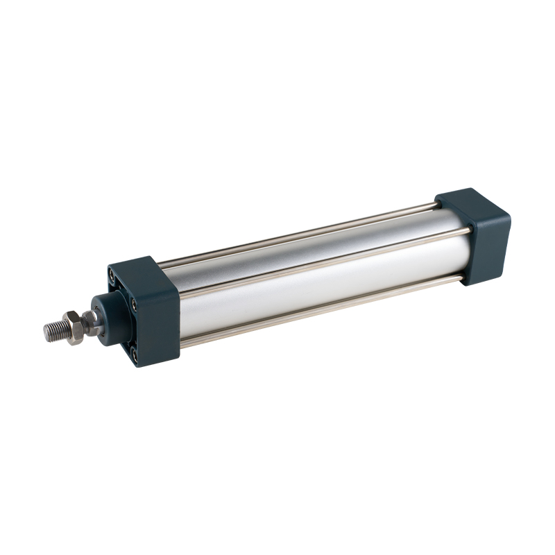 SC Series Tie-Rod Standard Cylinder for ISO 15552 ApplicationsThis tie-rod cylinder follows the ISO 15552 envelope, offering interchangeable mounting and port positions. Available from 32 to 100 mm bores with adjustable cushioning and high-temperature seals, it suits general automation tasks requiring reliable force.View Product →
The SC series tie-rod cylinders follow the ISO 15552 envelope, so the mounting distances, rod threads, and port positions align with other manufacturers using the same standard. If you need to compare complete specifications across bore sizes, the CKT air cylinder range lists structural drawings and mounting dimensions for every series in this progression.
Bore Sizing: Work Backward from the Load
The starting point for bore selection is always the load. The governing equation is F = P x A, where F is the required force, P is the working pressure, and A is the piston area. In metric units, if P is in N/cm² and A is in cm², the force comes out in newtons. At 6 bar, the pressure is roughly 60 N/cm² (0.6 MPa). A 50 mm bore has a piston area of 19.63 cm², so the theoretical push force is 19.63 x 60, or about 1178 N.
A typical example: a picking unit must push a 500 N load horizontally with a line pressure of 6 bar. The minimum area is 500 divided by 60, which equals 8.33 cm². A 32 mm bore delivers 8.04 cm², which is slightly below that value. After adding the usual 25 to 50 percent safety margin for seal friction, pressure drops, and acceleration forces, the correct choice is the next standard bore: 40 mm, with a piston area of 12.57 cm². That gives 754 N of theoretical force and roughly 565 N of usable force at 75 percent efficiency, leaving a comfortable reserve above the 500 N requirement.
| Bore (mm) | Piston area (cm²) | Force at 6 bar (N) | Suggested working load (N) |
|---|---|---|---|
| 16 | 2.01 | 121 | 60 - 90 |
| 20 | 3.14 | 188 | 95 - 140 |
| 25 | 4.91 | 295 | 150 - 220 |
| 32 | 8.04 | 482 | 240 - 360 |
| 40 | 12.57 | 754 | 375 - 565 |
| 50 | 19.63 | 1178 | 590 - 885 |
| 63 | 31.17 | 1870 | 935 - 1400 |
| 80 | 50.27 | 3016 | 1510 - 2260 |
| 100 | 78.54 | 4712 | 2360 - 3530 |
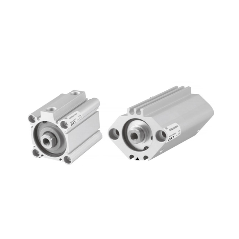 CQ2 Series Compact Thin Cylinder with Recessed Magnetic SwitchA thin-profile cylinder that saves vertical space while maintaining the same bore force. Its recessed magnetic switch prevents damage and is resistant to water, coolant, and strong magnetic fields, making it practical for tight or harsh environments.View Product →
In machines where vertical space is tight, a compact thin cylinder such as the CQ2 series uses the same bore size but a much shorter body, which changes the stroke range and cushioning options. The force calculation stays identical because the bore has not changed; only the installed envelope and the maximum available stroke change. Always verify those limits before choosing a compact body over a standard body.
Stroke Length: True Travel Plus Clearance
The stroke is not simply the distance the machine needs to move. It is the distance between the hard stops at both ends of the motion. If a pusher must reach 300 mm past the front mounting face, but the load carrier itself requires 20 mm of clearance at the retracted position and another 15 mm at the extended position, the cylinder stroke must be at least 335 mm. Many field replacements fail because the stroke was chosen from the nominal travel specification without including end-of-stroke clearances, shock absorber mounting space, or the thickness of the attachment plate.
Long strokes introduce a separate set of constraints. A 250 mm stroke is simple for most bores. A 1000 mm stroke with the same bore requires a larger rod, a longer cushioning zone, and almost always an external guide to prevent the rod from sagging under its own weight plus the load. Standard cylinders list a maximum stroke for each bore and rod combination; exceeding that value usually forces a custom build or an oversized rod option. When a design calls for a stroke more than eight to ten times the rod diameter, plan for a support bearing, a linear guide, or a slide table rather than a bare rod.
- End cushioning: adjustable cushions require 15 to 30 mm of stroke before the cushion seal engages; without that reserve, the piston slams into the end cap at full speed.
- Magnetic switches: the piston must travel completely through the switch sensing zone; a stroke that is too short leaves no reliable dwell signal for the PLC.
- Coupler clearance: if a floating rod coupler is used, it needs axial clearance on one side; forgetting this is a common cause of "no stroke" complaints on new installations.
- Oversizing strokes: adding 50 mm of extra stroke to gain flexibility raises air consumption, increases bending moment on the rod, and lengthens cycle time due to the extra travel distance.
Rod Diameter: Where Push and Pull Numbers Diverge
The rod diameter affects two separate things: the retract force and the buckling resistance. On the extend stroke, the full piston area sees the working pressure. On the retract stroke, the piston area is reduced by the cross-section of the rod, so the available force is always lower. For a 40 mm bore with a 16 mm rod, the push force is 754 N and the retract force is approximately 634 N at 6 bar. A thicker rod improves stability but costs more retract force. A thinner rod keeps the retract force high but limits the compressive load capacity at long strokes.
The buckling relationship is worth memorizing because it explains most rod failures. Euler's buckling formula shows that the critical load scales with the fourth power of the rod diameter. Halving the rod diameter reduces the acceptable compressive load to one sixteenth of the original value. A 1000 mm stroke with a 16 mm rod that handles 1200 N in compression can fail if the rod is swapped to a 10 mm rod without adding external guidance. For vertical press applications, always check the rod diameter against the stroke and the load direction; a perfectly reasonable bore selection is frequently invalidated by a rod that is too slender for the stroke.
Rod surface quality also belongs in the dimension conversation. A rod that is nominal in size but has scratches, nicks, or chrome wear will leak through the rod seal quickly. When measuring a used cylinder before replacement, measure the rod in two directions and compare the readings; oval wear of more than 0.05 mm is a reliable sign that the rod and seal were operating under excessive side load.
Mounting Dimensions: Match the Envelope, Not Just the Bore
Two cylinders with the same bore and stroke can have completely different installed dimensions because of the mounting style. ISO 15552 defines the most common mounting options: front flange, rear flange, rear clevis, rear lug, foot mount, and trunnion. Each mounting style changes the total length, the bolt pattern, and the space needed around the cylinder for motion or access.
| Mounting code | Mounting type | Dimensional effect | When to use |
|---|---|---|---|
| MS1 | Rear clevis | Adds clevis length behind the cap; requires swing clearance | Pivoting or oscillating load paths |
| MP2 | Foot mount | Lowers the mounting surface below the centerline; stable base | Horizontal pushes with fixed height brackets |
| MF1 | Front flange | Flange on the head plate; supports the load-bearing end | Tension loads, vertical mounting, compact fixed brackets |
| MT4 | Trunnion | Adds trunnion pins on the barrel; requires clearance around the body | Dumping, tilting, and rotating motion |
During a cross-brand replacement, the model number is never enough. Request the dimension drawing for the exact mounting style, then compare the overall length, bolt hole distance, rod thread size, and port position. A 40 mm bore cylinder from one manufacturer can be 12 mm longer than another with the same nominal size, which is more than enough to collide with a guard, a sensor bracket, or the next station. This is the most frequent dimensional mismatch found during retrofit projects.
Port Sizes and Air Demand: Dimensioning the Whole Chain
The cylinder port size is the interface between the actuator and the valve, and it follows the bore range in a predictable pattern. Small bores use M5 or G1/8 threads, mid-range bores use G1/4, and large bores use G3/8 or G1/2. Choosing a port that is too small restricts the flow, slowing the cycle; choosing a port that is too large adds cost and makes the fittings bulky for no performance gain.
| Bore range (mm) | Typical port thread | Recommended tubing OD | Suggested valve size |
|---|---|---|---|
| 8 - 16 | M5 or G1/8 | 4 - 6 mm | Direct-acting valve |
| 20 - 25 | G1/8 | 6 - 8 mm | Pilot-operated valve |
| 32 - 40 | G1/4 | 8 - 10 mm | 5/2 or 5/3 valve |
| 50 - 63 | G1/4 or G3/8 | 10 - 12 mm | 5/2 valve with rapid exhaust |
| 80 - 100 | G3/8 or G1/2 | 12 - 16 mm | Large-capacity 5/2 valve |
Air consumption is another dimension-related calculation that prevents undersized compressors and pressure drops. The free-air volume per single stroke is approximately the piston area multiplied by the stroke, multiplied by the compression ratio of the working pressure. For a 63 mm bore with a 200 mm stroke at 6 bar, the extension consumes about 4.3 liters of free air and the retract consumes about 4.1 liters. At 20 double cycles per minute, that is roughly 170 liters per minute of free air demand through the cylinder alone, before adding the valve pilot consumption and leakage. A closer look at how cylinder internals convert air pressure into practical motion helps when interpreting these numbers in a real circuit, and the explanation goes beyond the dimension sheet.
Fitting a speed control valve directly to the cylinder ports is common practice, but the exhaust flow through that fitting limits the maximum piston speed. If the dimensioned rod speed is critical to cycle time, check the flow rating of the fitting and the valve together; the cylinder itself is rarely the restriction.
Measuring an Installed Cylinder When the Nameplate Is Gone
Replacement work often starts with a worn-out cylinder whose model tag is oil-stained or scratched beyond reading. In that situation, the dimension set has to be recovered from the hardware itself. The sequence below gives reliable results on most standard cylinders.
- Measure the stroke from the rod. Extend the cylinder and measure the exposed rod length from the rod bearing face to the rod end. Retract it and measure again. The difference between the two readings is the stroke. This method is accurate to about 0.5 mm when the rod end is clean.
- Identify the bore from the tube outside diameter. For round cylinders, the tube OD is typically the bore plus 3 to 6 mm of wall thickness. Measure the OD across two directions, then match it against the manufacturer dimension table for the suspected series. On tie-rod cylinders, the distance between the tie rods is a more reliable bore identifier than the tube OD.
- Measure the rod diameter with a caliper. Take readings in two perpendicular directions and at two distances from the rod end. The smaller reading is the effective rod size; differences of more than 0.05 mm indicate wear.
- Record the mounting dimensions. Measure the distance between mounting holes, the hole diameter, the flange thickness, the distance from the rod centerline to the mounting surface, and the overall length with the rod retracted.
- Identify the port threads. Use a thread pitch gauge or test fittings. The common candidates are M5, G1/8, G1/4, G3/8, and G1/2. Never force a fitting; a damaged port turns a simple replacement into a cylinder body replacement.
- Order the drawing before ordering the part. Compare your measured values against the manufacturer's dimension sheet for the candidate model. The bore, stroke, rod, and mounting style must all match; a single mismatch is enough to stop the installation.
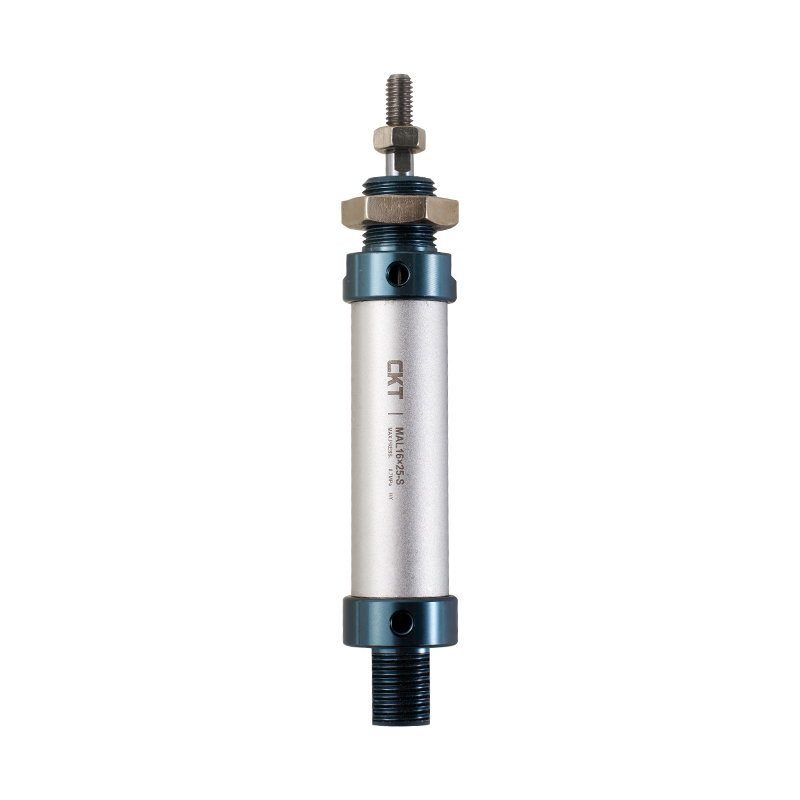 MAL Series Aluminum-Alloy Mini Cylinder for Common Replacement NeedsA lightweight aluminum round-tube cylinder with threaded end covers and self-lubricating bearings. Available in 20 to 40 mm bores, it is a typical miniature cylinder used in packaging and handling equipment, ideal for field measurement-based replacements.View Product →
For maintenance replacements in the small-bore range, the MAL series aluminum-alloy mini cylinder is one of the most common frames found in packaging and material-handling equipment. Its body flat-to-flat dimension, port thread, and rod thread follow a regular pattern that makes field measurement straightforward when the original model tag is gone.
Dimensional Mistakes That Only Show Up After Installation
Some dimension errors are invisible on paper and obvious on the machine. The list below collects the most common ones encountered during commissioning and retrofit work.
- Undersized bore with a theoretical surplus. A 25 mm bore at 6 bar delivers 295 N in theory. If the real demand is 280 N with old seals, a pressure drop of 15 percent, and a fast-accelerating mass, the cylinder will stall when the production rate rises. Experienced teams design in at least 30 percent usable-force margin above the nominal load.
- Oversized bore with hidden costs. A 100 mm bore consumes roughly four times the air of a 50 mm bore for the same stroke. The larger cylinder also needs bigger ports, heavier brackets, and longer cushioning time. Bigger is not safer; it is just more expensive to operate.
- Stroke selected without end clearance. A cylinder that travels exactly to the nominal stroke will hit the machine frame or the product stop at full speed. Always add clearance at both ends, and add cushioning travel if the speed exceeds 500 mm/s.
- Metric and imperial dimensions mixed. A 1/2 inch bore is 12.7 mm, not 12 mm or 16 mm. Rods that are 6 mm versus 1/4 inch (6.35 mm) look identical to the eye but fail differently under load. Always measure in one system and convert explicitly.
- Ignoring the retract force. A cylinder that pushes a 600 N load vertically can often extend, but it may not retract the same load if the rod is thick and the effective retract area is small. Check the pull direction with the actual rod diameter, not just the bore.
- Not checking the switch groove position. The piston position at which a magnetic switch triggers depends on the distance between the switch groove and the end caps. A cylinder with the same bore but a different body profile can move the switch trigger point by several millimeters, which is enough to break a timing sequence.
Frequently Asked Questions
What does 32 x 100 mean on a pneumatic cylinder label?
It means 32 mm bore and 100 mm stroke. This is the most common way manufacturers summarize the two primary dimensions on the nameplate. The rod diameter is usually listed separately or included in the model code.
How much force can a 50 mm bore cylinder produce at 6 bar?
The theoretical push force is approximately 1178 N. In practice, seal friction and line pressure losses reduce the usable force to roughly 600 to 900 N depending on speed, fitting size, and lubrication state.
Does the rod diameter change the push force?
No. The push force is calculated from the full piston area. The rod diameter only reduces the effective area on the retract stroke, which lowers the pull force.
Can I replace an ISO 15552 cylinder with an ISO 21287 compact cylinder of the same bore and stroke?
Only if the mounting pattern, overall length, port positions, and rod thread are compatible. A compact body is much shorter, but the hole spacing and cushioning options differ. Always compare the dimension drawings before ordering.
What happens if I choose a stroke longer than required?
The cylinder will still work, but it consumes more air, extends the cycle time, increases the bending moment on the rod, and takes up more machine space. Long strokes also increase the risk of buckling when the load is unsupported.
How do I find the port size on a cylinder that is still installed?
Measure the thread with a thread pitch gauge or try known test fittings. The most common pneumatic ports are M5, G1/8, G1/4, G3/8, and G1/2. Identifying the thread correctly prevents damage to the cylinder port during fitting installation.
What is the maximum stroke for a given bore size?
Each manufacturer publishes maximum stroke values for every bore and rod combination. Beyond those values, the rod buckling resistance and the body stability become the limiting factors. For long strokes, a larger rod or an external linear guide is mandatory.
Key Takeaways Before You Order
Selecting a pneumatic cylinder by dimensions is a systematic exercise. Start with the force requirement and the available pressure to fix the bore. Convert the machine's travel path into a stroke number that includes clearances and cushioning. Verify the rod diameter against both the retract force and the buckling risk. Then check the mounting style, port size, and overall length against the physical envelope. These five checks cover more than 90 percent of the dimensional issues that cause field failures.
Keep the dimension drawing from the manufacturer as the final authority. Model-to-model variations between brands are real, and a millimeter difference in a mounting bracket is enough to delay a production restart. The time spent measuring twice on the old cylinder is always shorter than the downtime caused by the wrong replacement.