

 中文简体
 English


Content
- 1 What Is a Pneumatic System? A Direct Answer
- 2 How a Pneumatic System Works: From Compressor to Actuator
- 3 Core Components of a Pneumatic System
- 4 Pneumatic vs Hydraulic Systems: Key Differences
- 5 Where Pneumatic Systems Are Used
- 6 Design and Sizing Considerations for Pneumatic Systems
- 7 Maintenance and Troubleshooting Basics
- 8 Frequently Asked Questions
- 8.1 What is the main difference between a pneumatic system and a hydraulic system?
- 8.2 What are the essential components of a pneumatic system?
- 8.3 What pressure do most pneumatic systems operate at?
- 8.4 Can a pneumatic system create vacuum?
- 8.5 How do I choose the right pneumatic cylinder?
- 8.6 What maintenance does a pneumatic system need?
- 9 Key Takeaways
What Is a Pneumatic System? A Direct Answer
A pneumatic system is a mechanical network that uses compressed air or gas to transmit and control energy. It converts electrical energy from a compressor into pneumatic energy, then back into linear motion, force, or vacuum. In industrial settings, most pneumatic systems operate at pressures between 0.4 and 0.8 MPa (about 58 to 116 psi), as defined by common standards such as ISO 4414. The core idea is simple: air becomes the working fluid that pushes pistons, turns valves, and grabs parts.
If you are designing a machine, maintaining a production line, or specifying components, you need to understand three things: how air is prepared, how it is controlled, and how it performs work. Pneumatic systems are popular because they are clean, overload-safe, and relatively low-cost. They do have limitations, including lower energy efficiency than electric drives and noise from exhaust. The sections below explain the working principle, key components, selection criteria, and practical maintenance steps.
How a Pneumatic System Works: From Compressor to Actuator
A pneumatic circuit follows a clear sequence. Understanding this flow helps you diagnose pressure drops, moisture problems, and slow cycle times. Here is the typical path of compressed air:
- Air intake and compression: An air compressor draws in ambient air and compresses it. Most industrial compressors are reciprocating, rotary screw, or rotary vane types. The compressor raises pressure to 0.7 to 1.0 MPa (100 to 145 psi) in the receiver tank.
- Cooling and drying: Compressed air leaves the compressor hot and saturated with water vapor. Aftercoolers and refrigerated dryers reduce the dew point, preventing condensation in pipes and valves.
- Filtration and storage: A receiver tank stabilizes pressure and stores air for peak demand. Filters remove particles, oil, and remaining moisture. The air is now ready for distribution.
- Point-of-use treatment: A filter-regulator-lubricator (FRL) unit at the machine adjusts pressure to the required level and adds lubrication if needed for specific valves or cylinders.
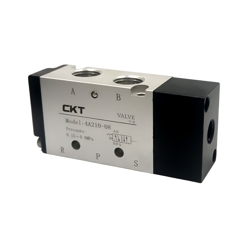
- Directional control: Solenoid valves, manual valves, or mechanical valves direct air to the correct port of an actuator. A 5-way valve is common for double-acting cylinders, allowing extend and retract motions.
- Actuation: Air enters a cylinder, vacuum generator, or air motor. The pressure acts on a piston or vane, producing force and motion. For a cylinder, force equals pressure times piston area.
- Exhaust and silencing: Air leaves the actuator through an exhaust port. Silencers reduce noise, and speed control valves (such as AS series) regulate exhaust flow to set cylinder speed.
Each step introduces potential losses. A 0.1 MPa pressure drop across a filter or long hose can reduce cylinder force by 15 to 20 percent. That is why system design starts with a pressure and flow budget, not just component selection.
Core Components of a Pneumatic System
A pneumatic system is only as reliable as its weakest component. The list below covers the essential hardware, from air preparation to final actuation. CKT Pneumatic, for example, manufactures over 20,000 accessory types and produces more than 90 percent of its parts in-house, which supports consistent quality across the chain.
Air Preparation: FRL Units, Filters, and Dryers
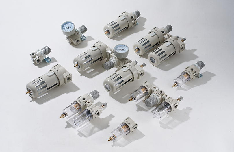
Compressed air must be clean, dry, and at the right pressure. A modular FRL unit combines a filter, regulator, and lubricator. The filter removes water and particles down to 5 microns or smaller. The regulator holds pressure steady, typically within plus or minus 0.02 MPa. The lubricator adds oil mist for tools or valves that require it. For precision applications, a dedicated precision regulator such as the IR series can hold pressure within 0.005 MPa.
Control Valves: Solenoid, Manual, and Mechanical
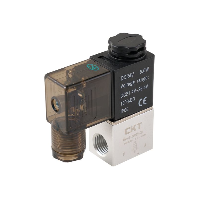
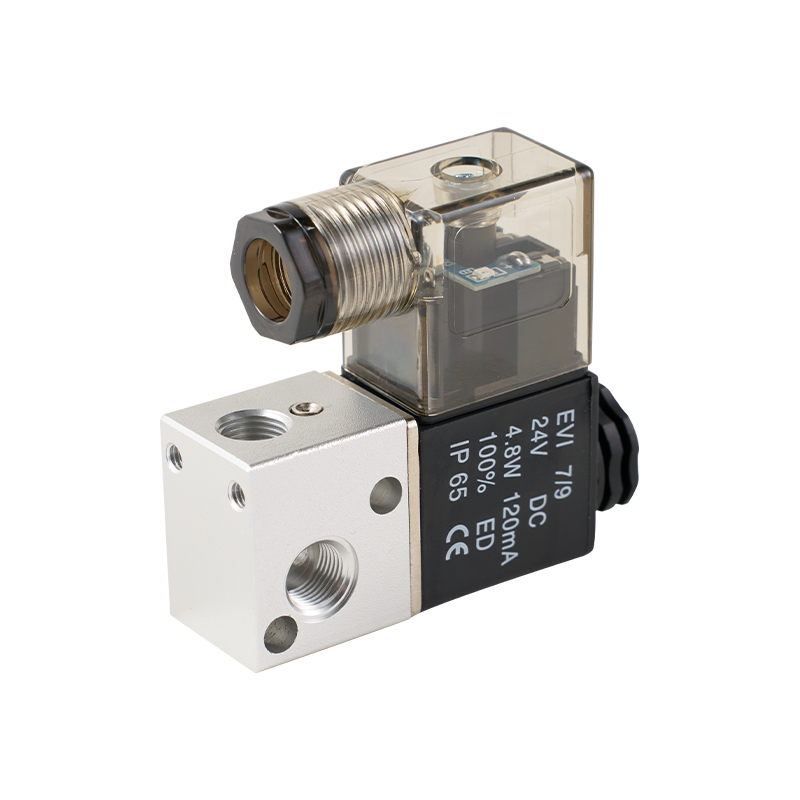
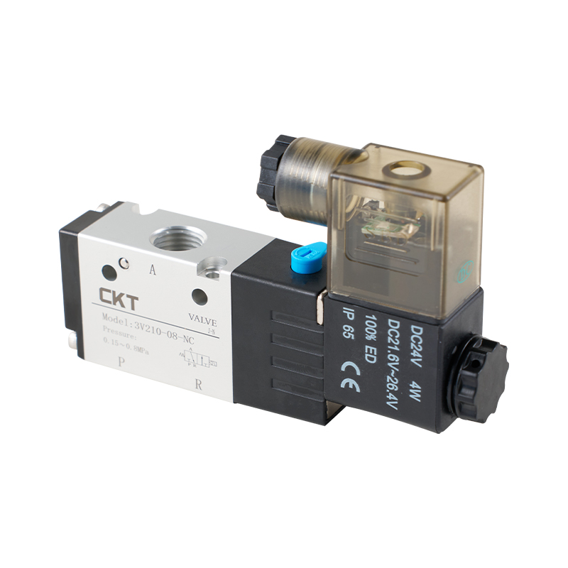
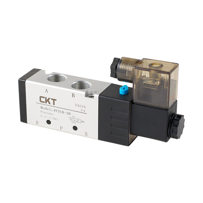
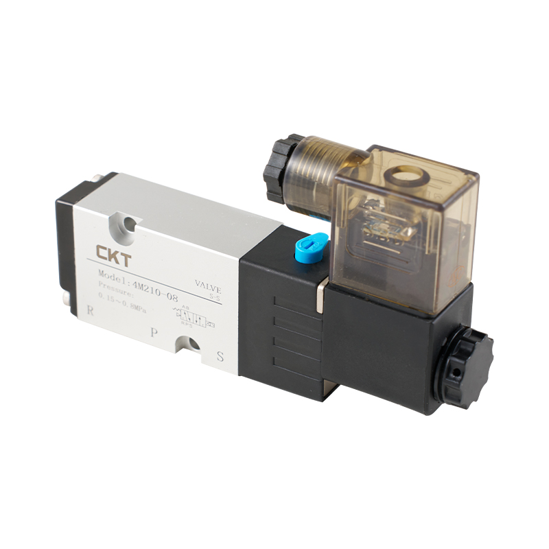
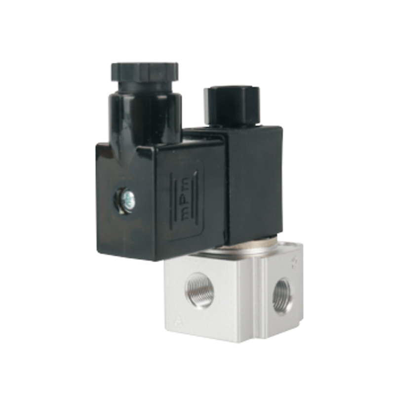
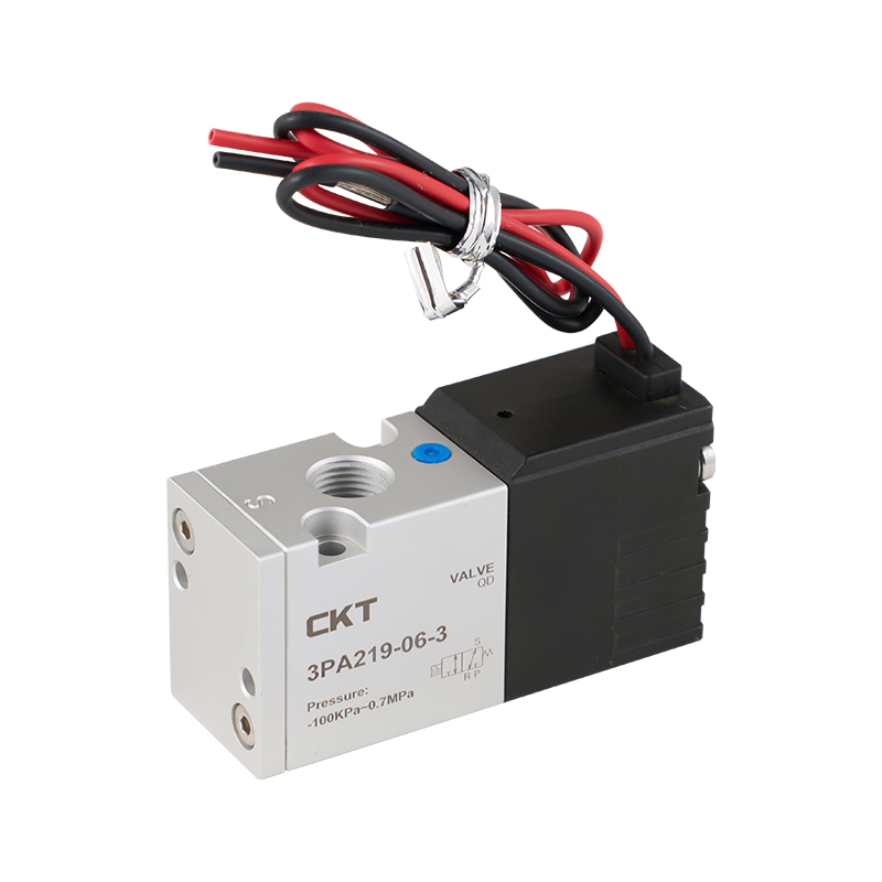
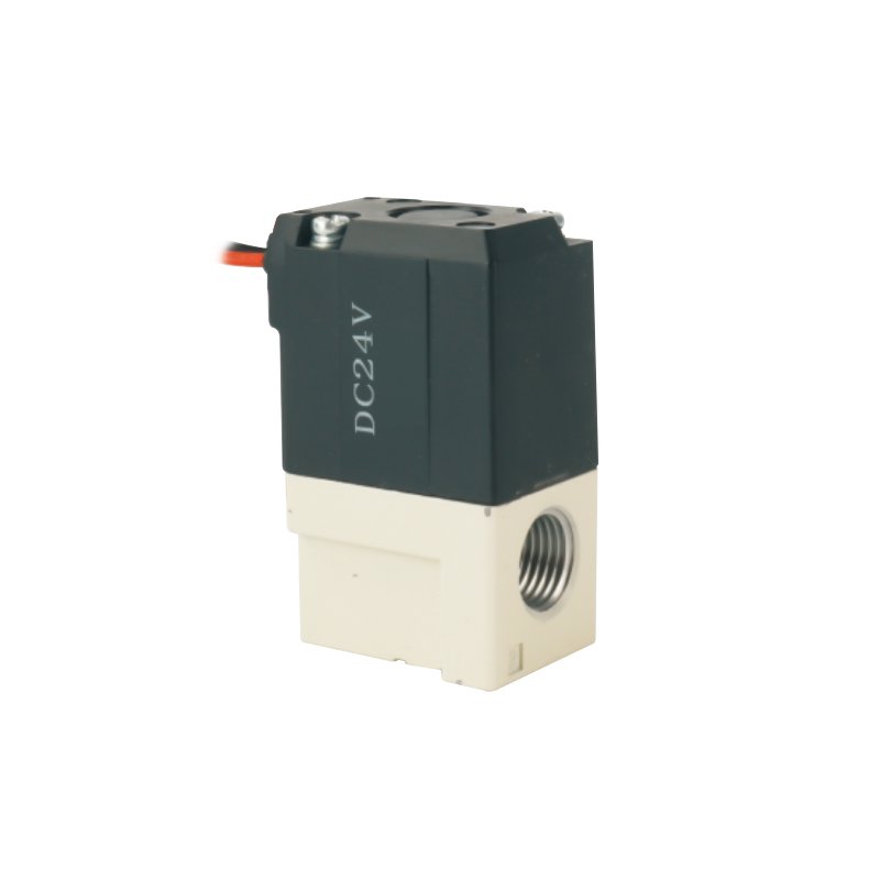
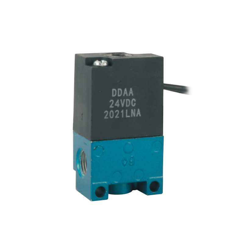
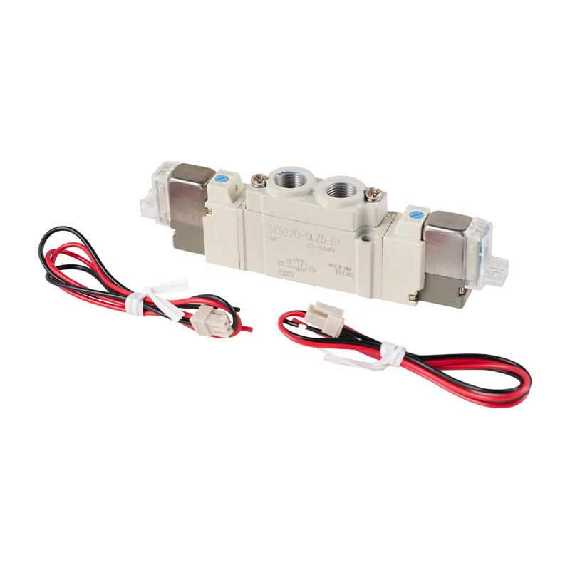
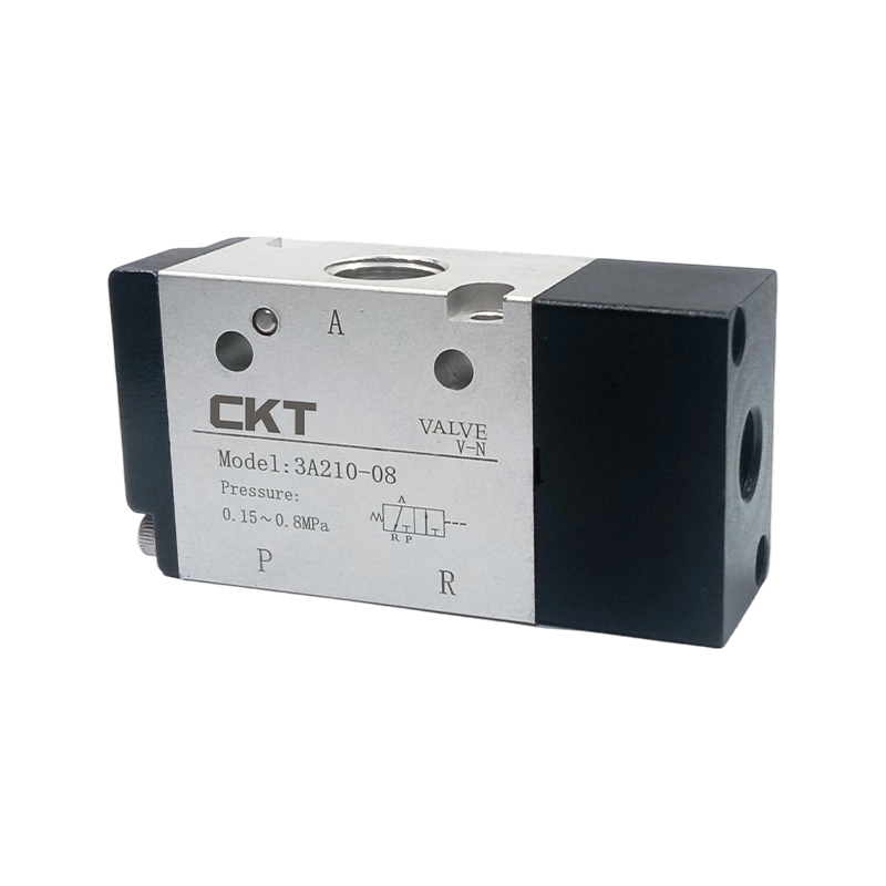
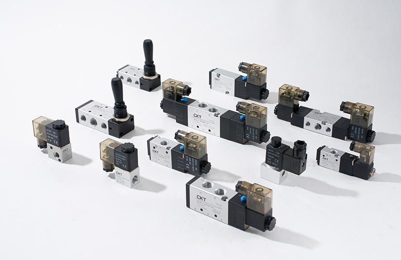
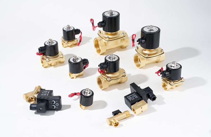
Directional control valves determine when and where air flows. A 2-position, 5-way solenoid valve is the workhorse for double-acting cylinders. Pilot-operated designs use a small electromagnetic pilot to shift a larger spool, which reduces power consumption and heat. Manual valves, foot valves, and mechanical valves provide operator or cam-based control. Flow control valves, including speed controllers and quick exhaust valves, manage actuator speed and cycle time.
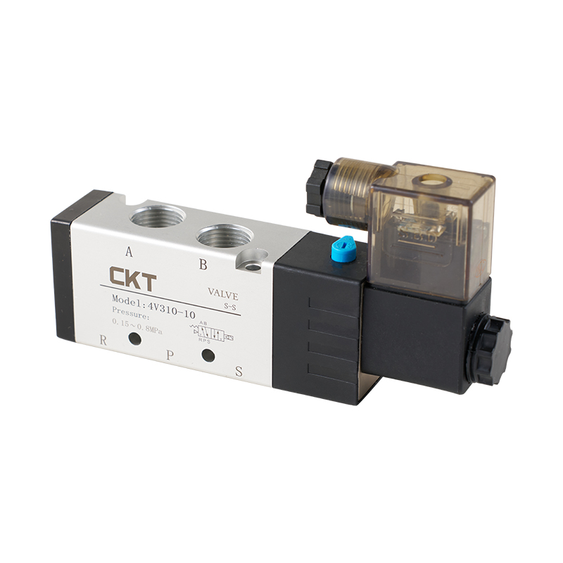 4V Series Pilot Operated 5 Way Solenoid Valve4V series pilot operated 5-way solenoid valves, designed for industrial pneumatic systems, accurately control the flow of compressed air through electrical signals, an...View Product →
Actuators: Cylinders, Rotary Actuators, and Grippers
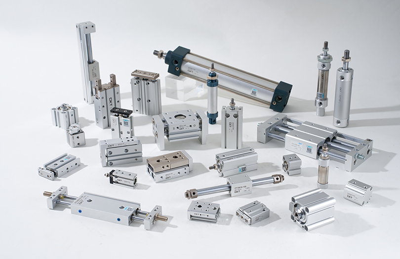
Cylinders convert air pressure into linear force. Standard cylinders, such as the CA2 series, handle general pushing, pulling, and clamping. Thin cylinders save space in compact fixtures. Rodless cylinders, including magnetic-coupled types, provide long strokes without a protruding rod. Rotary actuators produce controlled turning motion for indexing or flipping. Pneumatic grippers use parallel or angular jaws to hold parts during assembly or packaging.
 CA2 Series Standard Cylinders1. The mass is 5~15% lighter than the CA1 series; 2. The buffering capacity is improved, and the piston rod will not extend rapidly; 3. The buffer valve is easier to a...View Product →
Vacuum Components: Generators, Cups, and Filters
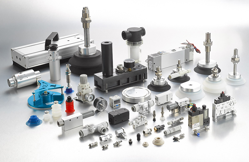
Many pneumatic systems create vacuum instead of positive pressure. A vacuum generator uses the Venturi effect to produce suction from compressed air. Multi-stage generators achieve higher vacuum flow with lower air consumption. Vacuum cups, made from rubber or polyurethane, grip smooth, rough, or delicate surfaces. Vacuum filters protect the generator from dust and debris. Vacuum saving valves cut air consumption by up to 90 percent when the cup seals against a part.
 ZH Series Vacuum GeneratorZH Series Vacuum Generator is a pneumatic component that performs well in the field of industrial automation. With its unique design and excellent performance, it is w...View Product →
Accessories: Fittings, Tubing, Silencers, and Sensors
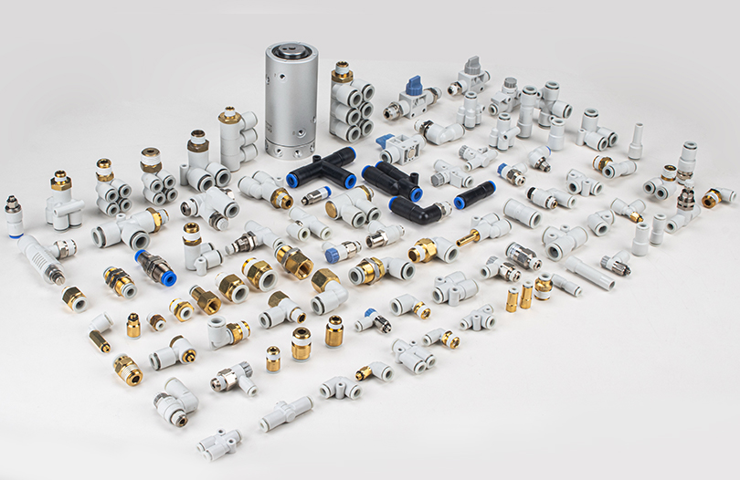
One-touch fittings simplify tubing connections and reduce assembly time. PU tubing is flexible and resistant to kinks. Silencers lower exhaust noise from 95 dB to below 70 dB in many cases. Magnetic switches mount on cylinders to provide position feedback to a PLC. Digital pressure switches, such as the ZSE/ISE series, monitor air pressure and send signals when readings fall outside a set range.
Pneumatic vs Hydraulic Systems: Key Differences
Choosing between pneumatics and hydraulics often comes down to force density, speed, and cost. The table below summarizes the practical differences. Use it as a starting point, then verify with your specific load and cycle requirements.
| Factor | Pneumatic System | Hydraulic System |
|---|---|---|
| Working fluid | Compressed air or gas | Oil or water-based fluid |
| Typical pressure | 0.4 to 0.8 MPa | 10 to 35 MPa |
| Force density | Lower, limited by bore size | Very high, compact actuators |
| Speed | Fast, up to 1 m/s or more | Moderate, controlled by valves |
| Precision | Good for on/off, harder for mid-stop | Excellent, easy to hold position |
| Cost | Lower initial cost, higher energy cost | Higher initial cost, higher efficiency |
| Typical applications | Packaging, assembly, pick-and-place | Presses, excavators, injection molding |
Pneumatics excel in clean environments where leaking oil would be a problem. They also tolerate overload better: if a cylinder stalls, air simply compresses further, and the system does not burst. Hydraulics win when you need high force in a small package or precise position holding under load.
Where Pneumatic Systems Are Used
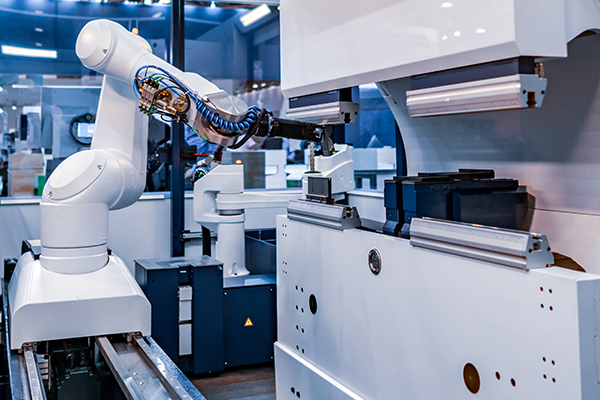
Pneumatic systems appear in almost every automated facility. Their simplicity, low maintenance, and ability to work in wet or dusty areas make them a default choice for many tasks. CKT Pneumatic, with its background in vacuum and pneumatic components since 2002, supplies actuators, valves, and air treatment units to these industries. You can read more about CKT Pneumatic's manufacturing background to understand the scale of its component range.
- Material handling: Vacuum cups and grippers lift glass, cardboard, metal sheets, and plastic parts. Rodless cylinders move loads along linear axes without a protruding rod.
- Packaging: Cylinders actuate sealing jaws, index star wheels, and push products into boxes. Multi-fold corrugated suction cups handle flexible bags that would collapse under a rigid gripper.
- Assembly: Pneumatic screwdrivers, presses, and clamps provide consistent force. Air blow-off nozzles clean debris from parts before assembly.
- Food and beverage: Stainless steel cylinders and FDA-compliant tubing resist washdown chemicals. Pneumatic systems avoid electrical sparks in flammable atmospheres.
- Automotive: Welding fixtures, engine assembly lines, and paint booths rely on pneumatics for clamping, lifting, and positioning.
- Electronics: Miniature cylinders and vacuum pens place tiny components without damaging them. Static elimination uses ionized air, often driven by pneumatic nozzles.
In each case, the system must match the environment. High humidity demands better drying. High cycle rates require faster valves and properly sized exhaust ports. Dusty plants need vacuum filters and covered cylinders.
Design and Sizing Considerations for Pneumatic Systems
A pneumatic system that works on paper may fail in production if you overlook pressure drop, air consumption, or duty cycle. The following guidelines come from common industry practice and component manufacturer data.
Calculate Force and Bore Size
For a cylinder, theoretical force equals air pressure times piston area. A 50 mm bore cylinder at 0.6 MPa produces about 1,178 N of force (F = P x A = 0.6 N per square millimeter x 1,963 square millimeters). In practice, subtract 10 to 15 percent for friction and return spring force if single-acting. Always apply a safety factor of at least 1.5. If you need 800 N of working force, choose a cylinder that delivers 1,200 N or more.
Account for Pressure Drop
Pressure drop occurs across filters, regulators, fittings, and long tubing runs. Keep total drop below 0.1 MPa to maintain actuator performance. A 10 mm inner diameter tube carrying 500 L/min of free air can lose 0.02 MPa per meter. If your compressor delivers 0.7 MPa, the cylinder might only see 0.55 MPa, reducing force by 21 percent. Undersized valves cause similar losses. Check the flow coefficient (Cv) of each valve and compare it to the required flow.
Air Consumption and Cost
Air consumption determines compressor size and operating cost. For a double-acting cylinder, free air consumption per cycle is approximately (piston area x stroke x 2 x pressure) / atmospheric pressure. A 32 mm bore, 100 mm stroke cylinder cycling 30 times per minute at 0.5 MPa consumes about 16.5 L/s of free air. At an energy cost of 0.12 USD per kWh, running that cylinder 8,000 hours per year costs roughly 620 USD. Vacuum saving valves and exhaust recovery can cut that figure significantly.
For a deeper look at pressure matching and sealing pitfalls, see this article on pneumatic component pressure matching and installation sealing.
Maintenance and Troubleshooting Basics
Most pneumatic problems trace back to contaminated air, leaks, or misadjusted controls. A simple maintenance routine prevents unplanned downtime.
- Daily: Drain water from receiver tanks, filters, and FRL bowls. Check for audible leaks at fittings and hoses.
- Monthly: Inspect filter elements and replace if pressure drop exceeds 0.05 MPa. Verify regulator settings with a calibrated gauge.
- Annually: Replace solenoid valve seals, lubricate cylinders if specified, and check rod alignment. Test emergency stop and exhaust functions.
Common symptoms and likely causes:
- Cylinder moves slowly or stalls: Check for pressure drop, closed speed control valve, or worn piston seals.
- Valve does not shift: Verify electrical signal, pilot pressure, and manual override. Moisture or debris in the spool bore can cause sticking.
- Excessive noise: Install or replace silencers. Check for worn bearings in the compressor or air motor.
- Vacuum drops: Inspect suction cup for wear, clean or replace vacuum filter, and check supply pressure at the generator.
Keep a spare parts kit for critical components. A failed solenoid valve or vacuum cup can stop an entire line. CKT Pneumatic holds over 20,000 part types in inventory, which helps reduce replacement lead time.
Frequently Asked Questions
What is the main difference between a pneumatic system and a hydraulic system?
Pneumatic systems use compressible air at lower pressures, typically 0.4 to 0.8 MPa. Hydraulic systems use incompressible oil at much higher pressures, often 10 to 35 MPa. Pneumatics are faster, cleaner, and cheaper to install. Hydraulics provide higher force in a smaller package and hold position better under load. The choice depends on force, precision, and environment.
What are the essential components of a pneumatic system?
Every pneumatic system needs an air compressor, a receiver tank, a dryer, filters, a pressure regulator, directional control valves, and actuators such as cylinders or vacuum generators. Accessories include fittings, tubing, silencers, and sensors. FRL units combine several air preparation functions in one module.
What pressure do most pneumatic systems operate at?
Industrial pneumatic systems commonly operate between 0.4 and 0.8 MPa (58 to 116 psi). The compressor may produce 0.7 to 1.0 MPa, but point-of-use regulators reduce pressure to match actuator requirements. Higher pressure increases force but also increases air consumption and wear.
Can a pneumatic system create vacuum?
Yes. A vacuum generator uses the Venturi principle: compressed air flows through a nozzle, creating a low-pressure zone that draws air from a suction cup. Multi-stage generators reach vacuum levels of -80 kPa or lower. Vacuum systems are widely used for pick-and-place of glass, cardboard, and electronic parts.
How do I choose the right pneumatic cylinder?
Start with required force, stroke length, and speed. Calculate bore size using F = P x A, then add a safety factor of 1.5 to 2. Consider mounting style, rod end thread, cushioning, and environment. For tight spaces, choose a thin or mini cylinder. For long strokes without a rod, use a rodless cylinder. For high precision, consider a slide cylinder with linear guides.
What maintenance does a pneumatic system need?
Drain moisture daily, check for leaks weekly, inspect filter elements monthly, and replace worn seals annually. Keep pressure drop below 0.1 MPa. Clean or replace silencers when they become clogged. For vacuum systems, inspect cups for cracks and clean filters regularly. A written maintenance log helps spot recurring issues.
Key Takeaways
A pneumatic system uses compressed air to transmit and control energy. It consists of air preparation, control valves, actuators, vacuum components, and accessories. Pneumatics offer fast, clean, and overload-safe operation at pressures around 0.4 to 0.8 MPa. They are less energy-efficient than hydraulics but cost less to install and maintain. Proper sizing, filtration, and routine maintenance prevent most problems. Whether you are building a new machine or optimizing an existing line, understanding the flow from compressor to actuator helps you make better component choices.
For specific product recommendations, explore CKT Pneumatic's range of cylinders, solenoid valves, FRL units, and vacuum generators. With over two decades of manufacturing experience and a deep inventory, CKT supports both small projects and high-volume production.